US1856073A - Lamp - Google Patents
Lamp Download PDFInfo
- Publication number
- US1856073A US1856073A US349921A US34992129A US1856073A US 1856073 A US1856073 A US 1856073A US 349921 A US349921 A US 349921A US 34992129 A US34992129 A US 34992129A US 1856073 A US1856073 A US 1856073A
- Authority
- US
- United States
- Prior art keywords
- frame
- lens
- door
- closure
- annular
- Prior art date
- Legal status (The legal status is an assumption and is not a legal conclusion. Google has not performed a legal analysis and makes no representation as to the accuracy of the status listed.)
- Expired - Lifetime
Links
- 238000006073 displacement reaction Methods 0.000 description 7
- 241000282472 Canis lupus familiaris Species 0.000 description 6
- 239000000463 material Substances 0.000 description 4
- 230000000717 retained effect Effects 0.000 description 4
- 239000011324 bead Substances 0.000 description 3
- 238000010276 construction Methods 0.000 description 3
- 239000011521 glass Substances 0.000 description 2
- 208000008103 Amniotic Band Syndrome Diseases 0.000 description 1
- RYGMFSIKBFXOCR-UHFFFAOYSA-N Copper Chemical compound [Cu] RYGMFSIKBFXOCR-UHFFFAOYSA-N 0.000 description 1
- 241000218652 Larix Species 0.000 description 1
- 235000005590 Larix decidua Nutrition 0.000 description 1
- 241000277331 Salmonidae Species 0.000 description 1
- 230000001154 acute effect Effects 0.000 description 1
- 230000006835 compression Effects 0.000 description 1
- 238000007906 compression Methods 0.000 description 1
- 230000003247 decreasing effect Effects 0.000 description 1
- 230000000694 effects Effects 0.000 description 1
- 230000037431 insertion Effects 0.000 description 1
- 238000003780 insertion Methods 0.000 description 1
- 108010085990 projectin Proteins 0.000 description 1
- 238000009877 rendering Methods 0.000 description 1
- 230000000630 rising effect Effects 0.000 description 1
- 238000007789 sealing Methods 0.000 description 1
- 230000035939 shock Effects 0.000 description 1
- XLYOFNOQVPJJNP-UHFFFAOYSA-N water Substances O XLYOFNOQVPJJNP-UHFFFAOYSA-N 0.000 description 1
Images

Classifications
-
- F—MECHANICAL ENGINEERING; LIGHTING; HEATING; WEAPONS; BLASTING
- F21—LIGHTING
- F21S—NON-PORTABLE LIGHTING DEVICES; SYSTEMS THEREOF; VEHICLE LIGHTING DEVICES SPECIALLY ADAPTED FOR VEHICLE EXTERIORS
- F21S8/00—Lighting devices intended for fixed installation
-
- F—MECHANICAL ENGINEERING; LIGHTING; HEATING; WEAPONS; BLASTING
- F21—LIGHTING
- F21V—FUNCTIONAL FEATURES OR DETAILS OF LIGHTING DEVICES OR SYSTEMS THEREOF; STRUCTURAL COMBINATIONS OF LIGHTING DEVICES WITH OTHER ARTICLES, NOT OTHERWISE PROVIDED FOR
- F21V17/00—Fastening of component parts of lighting devices, e.g. shades, globes, refractors, reflectors, filters, screens, grids or protective cages
-
- Y—GENERAL TAGGING OF NEW TECHNOLOGICAL DEVELOPMENTS; GENERAL TAGGING OF CROSS-SECTIONAL TECHNOLOGIES SPANNING OVER SEVERAL SECTIONS OF THE IPC; TECHNICAL SUBJECTS COVERED BY FORMER USPC CROSS-REFERENCE ART COLLECTIONS [XRACs] AND DIGESTS
- Y10—TECHNICAL SUBJECTS COVERED BY FORMER USPC
- Y10S—TECHNICAL SUBJECTS COVERED BY FORMER USPC CROSS-REFERENCE ART COLLECTIONS [XRACs] AND DIGESTS
- Y10S411/00—Expanded, threaded, driven, headed, tool-deformed, or locked-threaded fastener
- Y10S411/999—Expanded, threaded, driven, headed, tool-deformed, or locked-threaded fastener with retainer, e.g. tether
-
- Y—GENERAL TAGGING OF NEW TECHNOLOGICAL DEVELOPMENTS; GENERAL TAGGING OF CROSS-SECTIONAL TECHNOLOGIES SPANNING OVER SEVERAL SECTIONS OF THE IPC; TECHNICAL SUBJECTS COVERED BY FORMER USPC CROSS-REFERENCE ART COLLECTIONS [XRACs] AND DIGESTS
- Y10—TECHNICAL SUBJECTS COVERED BY FORMER USPC
- Y10T—TECHNICAL SUBJECTS COVERED BY FORMER US CLASSIFICATION
- Y10T292/00—Closure fasteners
- Y10T292/08—Bolts
- Y10T292/096—Sliding
- Y10T292/1014—Operating means
- Y10T292/1033—Screw
-
- Y—GENERAL TAGGING OF NEW TECHNOLOGICAL DEVELOPMENTS; GENERAL TAGGING OF CROSS-SECTIONAL TECHNOLOGIES SPANNING OVER SEVERAL SECTIONS OF THE IPC; TECHNICAL SUBJECTS COVERED BY FORMER USPC CROSS-REFERENCE ART COLLECTIONS [XRACs] AND DIGESTS
- Y10—TECHNICAL SUBJECTS COVERED BY FORMER USPC
- Y10T—TECHNICAL SUBJECTS COVERED BY FORMER US CLASSIFICATION
- Y10T292/00—Closure fasteners
- Y10T292/20—Clamps
Definitions
- This invention relates to electric lamps and more particularly to electrically operated :llood lights, search lights, headlights and the like, which are intended for the projection ct light over comparatively great distances or areas.
- Uonsiderahle diilicultv has been enperi enced in obtainin an ellective weather-tight seal hetween the lamp body proper and the l closure door throu h which access is ordinarily had to the interior of the lamp, as well as hetwecn the trontal lens oi the lamp and its retaining trame.
- certain ditticulties have been encountered in connection with the various types at clamping means employed tor drawing the closure door into secure position against the lamp body or casing.
- the present invention aims to ohviate the atorementioncd diliiculties by the provision of novel means tor hermetically sealing the trontal lens within its retaining trame, which latter also constitutes, in the present instance, the trame oil the closure door tor the lamp hody.
- the invention is the provision at means tor insuring a hermetic, weatherprool. seal hetween the closure door and the lamp hody proper when the former is drawn into closed position.
- a still :turther ohject ot the invention is the provision of improved clamping means which are operable to insure not only positive loclring ot the closure door in closed ness about the juncture between the lamp body and its door.
- the invention has as its further object the provision ozt door clamping means which are non-removahly secured to the closure door and by means ct which the said door may be readily and quickly clamped into closed position and as readily released therefrom.
- @till another object ofthe invention is the provision of means for resiliently, yet securely, retaining the frontal lens within the closure door frame whereby the former is effectively cushioned against shocks and the like, said means being compressible when the door is clamped into closedposition against the lamp body to afford a hermetically sealed Loint between said door and body as well as etween said door and the lens retained thereh
- Still another object oi the invention is the provision at a removable color screen which is retained by the closure door in operative association with the frontal le s.
- the invention consists substantially in the combination, construction, location and relative arrangement oi parts, all as will appear more tally hereinafter, as shown in the accompanying drawings, and as linally pointed out in the appended claims.
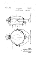
- lligure l is a front elevational viewot a lamp constructed in accordance with the present invention.
- Figure 2 is a side elevational view of the lamp as it appears when viewed from the right or" Figure l;
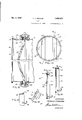
- igure 3 is a vertical section through the closure door of the lamp and the trout portion of the lamp body or casing;
- Figure 4 is a front elevational view of a portion oi? the closure door showing a modilied form of clamping means for retaining the door in closed position;
- Figure 5 is a view taken on the line 5-5 of Figure 4.
- FIG. 6 is a side elevation of the clamping means shown in Figure 5, the enclosure therefor being shown in section;
- Figure 7 is a perspective view of the door locking dog per se
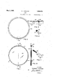
- Figure 8 is a view ot the lens retaining ring
- Figure 9 is an enlarged view of the detail shown within the dotted circle of Figure 8;
- Figure 10 is a sectional view taken along line 1010 of Figure 9;
- Figure 11 is a View of the removable color screen
- Figure 12 is a vertical section taken on the line 12-42 of Figure 11;
- a front door closure compre F' um 13 is a frontal elevation of a modi- )IlStlllCtlOIl of color screen;
- Figure 14 is a vertical section taken on the line 14-14 of Figure 13;
- Figure 15 is a partial vertical section through the closure door and the front portion of the lamp body, this view being taken on a line corresponding to line 14-14 of Figure 13 and showing the color screen mounted exteriorly of the frontal lens;
- Figure 16 is a vertical sectional view of a quick-detachable hood member or visor adapted to be substituted for the color screen shown in Figure 14;
- Figure 17 is a vertical sectional view .of a color screen similar to that of Figure 15 with which is operatively associated a slightly modified form of visor;
- Figure 18 is an enlarged view of the detail shown within the dotted circle of Figure 13.
- the lamp herein shown comprises a substantially drum-shaped body or casing 10 having a back wall 11.
- this back wall 11 which is dished outwardly to accommodate a suitable reflector (not shown), is formed integrally with the lamp body 10.
- the latter is provided with a frontal opening over which is fitted, in the manner to be described more fully hereiniensively designated by the reference numeral 12.
- the lamp body 10 is provided about its frontal edge with an annular bead or shoulder 13 referably formed integrally therewith. nasmuch as this invention is particularly directed to the front-closure door and arts immediately related thereto it is deeme unnecessary to describe herein any other features of the lamp taken as a whole.
- annular cushioning gasket 23 Suitably secured within “the outer and inclined recess or groove 19 of the door frame is an annular cushioning gasket 23 which is preferably a rubber tube compressed into the shape shown.
- This gasket 23 serves both as a cushioning element for the marginal flange 24 of a lens 25 and as a weathering thereabout to prevent entry of rain water, moisture or the like.
- the lens 25 is removably held in position against the cushioning gasket 23 by an annular retaining means 26, which, as shown in Figures 3 and 10, is of substantially angular cross-section having a branch 27 projecting into the inner groove 20 of the frame 18 and a rearwardly extending branch 28 forming an annular seat 29.
- the lens 25 is retained between the cushioning gasket 23 and the outwardly extending branch 27 of the retaining means 26.
- This latter means is split, as at 30, (see Figures 8 and 9) to facilitate its insertion in the groove 20 of the door frame.
- a strap 31 Suitablyinounted within the annular seat 29 adjacent one end of the split ring 26 and secured thereto, preferably by riveting, is a strap 31, a portion of which extends freely be ond the split 30 to overlie the opposite en of the ring.
- Formed in this latter end of the ring 26 is an elongated slot or opening 32 through which a suitably headed screw 33 passes into threaded engagement with the free end of the strap 31.
- a second cushioning gasket 34 is seated within the annular recess formed between the inner ortion 22 of the door frame and the rearwar ly extending branch 28 of the split ring 26.
- this cushioning gasket 34 is of substantially circular cross-section.
- the lens 25, the split ring 26- and the cushioning gasket 34 are all forced into intimate contact with each other and, as a unit, are forced against the outer cushioning gasket 23.
- This action ciated with each boss 36, the shank 39 thereof is permitted by reason of the fact that the groove 20 in the door frame 18 is of sufiicient width to permit lateral shifting of the split ring 26 therewithin.
- the inner cushioning, gasket 34 and the outer cushioning gasket 23 operate conjointly to provide a most effective means for rendering the joints between the lens 25 and the frame 18 and between said frame and (the lamp body 10 impervious to the entry of rainwater, moisture and thelike, at the same time that they cushion the lens against danger of fracture.
- clamping devices for retaining the closure door in tightly closed position against the lamp bodyv 10 will now be described.
- these clamping devices designated generally by the numeral 35, are preferably three in number and are uniformly spaced about the marginal edge of the door frame 18.
- integralally formed in the said frame 18 and projecting radially therefrom are a series of bosses or projections 36 having bores 37 therein which extend transversely across the plane of the closure door frame.
- a clamping member or dog 38 having an externally threaded shank 39 and a clamping aw 40 is operatively assobeing loosely received within the bore 37 of said boss such that its threaded extremity projects forwardly of the frontal edge of the door frame 18.
- the clamping jaw 40 is of substan-. tially triangular shape, the basal edge 41 thereof being arcuately formed to fit snugly against the perimetral surface of the lamp body 10.
- the inner face 42 of the clamping jaw 40 is arranged to normally engage the rear surface of the annular head 13 of the lamp body 10 at the same time that the basal edge 41 thereof rests snugly against the perimetral surface of the lamp body.
- a wing nut 42 Threadedly received upon the forwardly extending end of the shank 39 of the clamping member is a wing nut 42 having a. flange 43 normally bearing against the outer end of the boss 36.
- the outerflportion of the bore thereof is enlarged to provide an internal shoulder 44 therewithin.
- a suitable stop '45 is formed at the extremity of the shank 39, preferably by an bosses 46 each of which is provided with a transverse socket 47. v The rear wall of each socket 47 is apertured as at 48.
- the clamping dog 49 is similar to the dogs 38 described in connection with Figure 3 in that it is also provided with a threaded shank 50 and a clamping jaw 51.
- each dog 49 is projected into the interior of its corresponding socket 47 through the aperture 48 and is threadedly engaged by a suitable nut 52 received and arranged for rotation within said socket.
- a suitable nut 52 received and arranged for rotation within said socket.
- One end of this nut 52 abuts against the rear wall of the socket while the opposite end thereof is provided with a pair of diametrically opposed lugs 53.
- a tubular member 54 having a closed end 55 which projects outwardly of the open end of the socket.
- This tubular member 54 is provided in its inner end with a pair of diametrically opposed slots 56 which are arranged to respectively engage the lugs 53 of t-henut 52.
- the member 54 is maintained in spaced out-of-contact relation with the threaded shank of the clamping dog 49.
- annulargroove 57 provided in the external surface of the member 54, constitutes a seat for a pin 58 extending transversely of the socket 48.
- the annular groove 57 and the pin 58 cooperate to permit rotation but no axial movement of the tubular member 54 within its socket 48.
- the closed end 55 of the member 54 is kerfed, as at 59, to accommodate a suitable tool, such as a screw driver or the like, for effecting rotation of the nut 52 by rotation of the member 54.
- FIGs 11 and 12 are front and side views, respectively, of the removable color screen which is generally designated in Figure 3 by the reference numeral 60.
- This screen comprises an annular frame 61 within which is suitably glazed a lens 62 of glass l or other such transparent or translucent material.
- Thelens 62 is colored as desired, the screen being resiliently seated against the marginal rear surface of the front door lens 25 and within the lens retaining ring 26.
- ⁇ Vcldcd or otherwise suitably secured to the frame (ii of the color screen are a plurality of circumferentially spaced spring fingers (33, the free ends of which project rearwardly of the screen and the front door closure to prospring vide purchase elements for removing the screen from its operative position, as shown in Figure 3.
- Adjacent their points of secnremcnt to the color screen frame the several fingers 63 are each provided with resilient radially oil'set portions 64 by which a snap tit with the lens retaining ring 26 is permitted.
- Figures 13 and 14 are front elevational and vertical sectional views, respectively, of a modified construction of color screen assembly which is arranged for mounting exteriorly of the frontal lens and the supporting frame 18 therefor.
- This modified screen assembly comprises an annular frame within which is received a lens (56 of glass or other such transparent or translucent material, this lens being colored as desired, and being preferably composed of a plurality of sections separated from each other along the lines (37.
- the frame 65 comprises an annular band ($8 provided at the outer edge thereof with an integrally formed lens receiving groove (it).
- the grooved section of the frame is split, as at 70, see Figure 18) to facilitate reception of the lens 66 therewithin while the end 71 of the band 68 is extended beyond its corres ending end of the grooved section for over apping engagement with the opposite end of the .band.
- a rivet 72 or similar means is employed to secure the overlapping portions of the band 688 together.
- a Pinrality of circumferentially spaced spring fingcrs 73 each of these fingers being provided with a substantially flat portion 74 and a radially offset portion 7 5 curved to a shape to the external curvature of the door closure frame 18.
- the flat portion 74- of the spring fingers are secured upon the outer surface of the band 68 preferably by means of the rivets 76, it being observed that the inner edge 77 of the band 68 terminates in a plane intersecting the curved portions 75 of the. spring fingers.
- this invention contemplates the provision of a visor 78 (see Figure 16) having spring iingers 79 secured thereto and operative in the same manner as the fingers 73 previously described.
- the visor 78 may he quick-detachably mounted upon the door frame 18 in place of and in exactly the same manner as the color screen assembly shown in Fi ure 15.
- Figure 17 shows a visor 7 8 provi( ed with a somewhat modified form of spring finger 80 for detachably mounting the VlSOl upon the color screen assembly, the latter being in turn .adapted for detachable mounting'upon the door frame 18;
- this invention provides an cflicient and effective weather roof seal between the lens and its retaining rame and between the latter and the lamp body. This is accomplished not only by means of the particular arrangement of cushioning and weatherproofing gaskets hereinbefore described but also b means of the particular forms of clamping evices employed to draw the closure door into tightly closed position against the lamp body. Not only is the general arrangement simple in construction but it is also economical to roduce and assemble. It is to be noted that certain features of the invention are not articularly restricted to lamps of the special the drawings since they may be as readily embodied in lamps of smaller size and intended for other uses than those herein set forth. In conclusion, it will, be understood that various chan es may be made from time to time without departing from the general spirit or principles of the invention and it is accordingly intended to claim the same as indicated by the a pended claims.
- a front door closure thereforw comprising a substantially annular frame having a pair of axially spaced rooves formed in the innor surface thereo the outer of said grooves being inclined with respect to the axis of said frame, a compressible gasket received within said outer groove and aving a portion projecting exteriorly thereof, a ring received within the inner of said grooves, and a lens arranged with its perimetral edge interposed between said ring and the projecting portion of said gasket, said inner groove being of a width sufficient to permit axial movement .of said ring toward said lens and the latter into intimate contact with said gasket upon the application of an exernal force against said ring character shown in v 2.
- a front door closure therefor com rising a frame having a pair of axially space grooves formed in the inner surface thereof, a compressible gasket received within the outer of said rooves, a ring received within the inner of said grooves.
- said latter groove being of a width suflicient to permit axial displacement of said ring therewithin, a lens arranged with its marginal edge interposed between said gasket and ring, and compressible material associated with said ring, the latter being provided with means for retainiin said material in position independently of said lens.
- a lamp body having a frontal opening, a front door closure therefor adapted to seat against the marginal edge defining said opening, said closure comprising a frame provided with an inturned flange at the outer edge thereof and having a pair of axially spaced grooves formed in the inner surface thereof, the outer of said grooves being located in the zone of the angle formed between said frame and flange and being inclined with respect to the plane of the latter, a compressible gasket received within said outer groove, a lens'disposed'with the outer marginal surface thereof abutting said gasket, retaining means received within the inner of said grooves and arranged to abut the inner marginal surface of said lens, said retaining means being shiftable axially within its groove,- and means for drawing said closure tightly against said frontal edge Fill of the lamp body whereby to force said retaining means and said lens axially of said frame with the result that said lens intimately engages said gasket.
- a lamp body having a free edge defining an opening alfording access to the interior thereof, a closure for said opening comprising a frame, a lens removably positioned within said frame, weatherproofing means interposed between one surface of said lens and said frame for effect ing a hermetic seal therebetween, a retaining member interposed between said frame and the opposite surface of said lens to prevent displacement of the latter, said member be' ing provided with an annular portion projecting rearwardly of said lens and a second weatherproofing means carried by the annular portion of said retaining member independently of said lens for effecting a h'rmetic seal between said frame and said free edge of the lamp body, said retaining member and the weatherproofing means carried there- ;by being axially shiftable under compression.
- a lamp body having a free edge defining an opening aflording access to the interior thereof, a closure for said opening comprising a frame, a lens removably positioned wlthm said frame, fixed means on said frame for limiting the axial displacement of said lens in one direction,
- said shiftable means being provided with an annular portion substantially concentric with the inner portion of said frame to provide an annular space therebetween, weatherproofing means disposed within said annular space and adapted for engagement with said free edge of the lamp body, and means for drawing said closure into tightly closed position whereby to cause said weatherproofing means to be compressed between said free edge of the lamp body and said frame simultaneously as said shiftable means and said lens are forced, as a unit, axially to.- ward said fixed means.
- a closure for a lamp body comprising a frame provided with an annular abutment and an annular groove spaced axially with respect to said abutment, a lens retaining ring received within said groove, the latter being of a width sufficient to permit axial shifting of said ring therewithin, a lens removably positioned within said frame and between said abutment and axially shiftable ring, said ring being formed with an axially extending annular flange concentric with said-frame, and a weatherproofing gasket disposed within the annular space formed by said fram and flange, said gasket being inherently compressible and arranged for shifting movement with said ring.
- a front door closure comprising'a frame, a lens received therewithin, an annulus carried by said frame for preventing displacement of said lens, said annulus being provided with an axially extending annular flange concentric with said frame, a weatherproofing gasket received within the annular space afforded by said flange and frame to thereby constitute said gasket a part of said closure, and a color screen provided with means engageable within the flange for quick-detachably securing the screen therewithin.
- a front door closure comprising a frame having-a seat for a lens, a lens removably positioned therewithin and against said seat, an annulus operatively associated with said frame for preventing displacement of said lens, said annulus being provided with a flanged portion of gradually decreasing diameter whereby to form,
- a lamp body having an opening in one side thereof surrounded by an annular shoulder, a
- door closure including a frame arranged in embracing relation with respect to said shoulder and a lens ada ted to be compressed thereagainst, a lura ity of clampmg devmes projected axial y through circumferentially spaced bores formed in said frame, each of said devices bein provided with a clampm jaw adapted to e rotated into and out o engagement with said shoulder and w1th 9.
- a lamp body havin an opening in one side thereof surrounded by an annu ar shoulder, a door closure including,a frame arranged in embracing relation with respect to said shoulder and a lens ada ted to be compressed thereagainst, a lura ity of clamping devices projected axial y through circumferentially spaced bores formed in said frame, each of said devices being provided with a clamping jaw adapted to be rotated into and out of enga ement with said shoulder and with so a threa ed shank projecting forwardly of said frame and terminating short of the frontal plane thereof, a nut member disposed within each of said bores for threaded engagement with said shank for effecting axial movement of said devices within their respective bores whereby-to cause said lens to ,be forced against said shoulder, and means embracing the free end of each shank for actuating the nut member associated therewith, said means being further operative to prevent axial movement of said nut member.
- a front door closure comprising a frame, a lens received therewithin, an annulus carried by said frame for preventing displacement of said lens, said annulus being provided with an annular" flange concentric with said frame, a weatherproofing gasket received within the annular space formed between said flange and frame, a color screen, and spring means operatively associated. with the screen and enga eable within, the flange for quick-detachab y securing said screen therewithin.
Landscapes
- Engineering & Computer Science (AREA)
- General Engineering & Computer Science (AREA)
- Arrangement Of Elements, Cooling, Sealing, Or The Like Of Lighting Devices (AREA)
- Securing Globes, Refractors, Reflectors Or The Like (AREA)
Description
May 3, 1932. H. J. GRAHAM I 1,856,073
. LAMP I Filed March 26, 1929 4 Sheets-Sheet 1 TI g INVENTOR.
HERBERT J. GRAHAM A TTORNE Y.
May 3, 1932.
H. J. GRAHAM 1,856,073
LAMP
Filed March 26, 1929 4 Sheets-Sheet 2 awaeaeazazeze 1a.-..
INVENTOR. HERBERT J. GRAHAM -J 7 l8 BY M A TTORNE Y.
May 3, 1932.
H. J. GRAHAM 1,856,073
LAMP A Filed March 26, 1929 4 Sheds-Sheet s INVENTOR.
FIG, BY HERBERYJGRAHAM A TTORNE Y.
y 1932 H. J. GRAHAM 1,856,073
' LAMP Filed March 26, 1929 4 Sheets-Sheet 4 JNVE/VTOR. HERBERTJGRAHM AZZ'OR VU t n it ill position lout also a maximum of weathertight- Patented -May 3, 1932 UNITED STATES PATENT OFFICE HERBERT J. GRAHAM, F PHILADELPHIA, PEN N BYLVANIA, ASSIGNOB 1'0 ELECTRIC SERVICE SUPPLIES COMPANY, 01! PHILADELPHIA, PENNSYLVANIA, A CORPORATION 01? PENNSYLVANIA Lure Application ma larch 28,1929. Serial No. 349,92;
This invention relates to electric lamps and more particularly to electrically operated :llood lights, search lights, headlights and the like, which are intended for the projection ct light over comparatively great distances or areas.
Uonsiderahle diilicultv has been enperi enced in obtainin an ellective weather-tight seal hetween the lamp body proper and the l closure door throu h which access is ordinarily had to the interior of the lamp, as well as hetwecn the trontal lens oi the lamp and its retaining trame. Similarly, certain ditticulties have been encountered in connection with the various types at clamping means employed tor drawing the closure door into secure position against the lamp body or casing.
The present invention aims to ohviate the atorementioncd diliiculties by the provision of novel means tor hermetically sealing the trontal lens within its retaining trame, which latter also constitutes, in the present instance, the trame oil the closure door tor the lamp hody. 1
.dl turtlier object oil the invention is the provision at means tor insuring a hermetic, weatherprool. seal hetween the closure door and the lamp hody proper when the former is drawn into closed position.
A still :turther ohject ot the invention is the provision of improved clamping means which are operable to insure not only positive loclring ot the closure door in closed ness about the juncture between the lamp body and its door. In this connection, the invention has as its further object the provision ozt door clamping means which are non-removahly secured to the closure door and by means ct which the said door may be readily and quickly clamped into closed position and as readily released therefrom.
@till another object ofthe invention is the provision of means for resiliently, yet securely, retaining the frontal lens within the closure door frame whereby the former is effectively cushioned against shocks and the like, said means being compressible when the door is clamped into closedposition against the lamp body to afford a hermetically sealed Loint between said door and body as well as etween said door and the lens retained thereh I Still another object oi the invention is the provision at a removable color screen which is retained by the closure door in operative association with the frontal le s.
Other ob'ects ot' the invention will appear more tally ereinat'ter,
The invention consists substantially in the combination, construction, location and relative arrangement oi parts, all as will appear more tally hereinafter, as shown in the accompanying drawings, and as linally pointed out in the appended claims.
ln the accompanying drawings, which are merely illustrative of the principles ot the present invention:
lligure l is a front elevational viewot a lamp constructed in accordance with the present invention; 1
Figure 2 is a side elevational view of the lamp as it appears when viewed from the right or" Figure l;
Figure 4 is a front elevational view of a portion oi? the closure door showing a modilied form of clamping means for retaining the door in closed position;
Figure 5 is a view taken on the line 5-5 of Figure 4;
Figure 6 is a side elevation of the clamping means shown in Figure 5, the enclosure therefor being shown in section;
Figure 7 is a perspective view of the door locking dog per se;
Figure 8 is a view ot the lens retaining ring;
Figure 9 is an enlarged view of the detail shown within the dotted circle of Figure 8; Figure 10 is a sectional view taken along line 1010 of Figure 9;
Figure 11 is a View of the removable color screen;
Figure 12 is a vertical section taken on the line 12-42 of Figure 11;
lftt
till
' after, a front door closure compre F' um 13 is a frontal elevation of a modi- )IlStlllCtlOIl of color screen;
Figure 14 is a vertical section taken on the line 14-14 of Figure 13;
Figure 15 is a partial vertical section through the closure door and the front portion of the lamp body, this view being taken on a line corresponding to line 14-14 of Figure 13 and showing the color screen mounted exteriorly of the frontal lens;
Figure 16 is a vertical sectional view of a quick-detachable hood member or visor adapted to be substituted for the color screen shown in Figure 14;
Figure 17 is a vertical sectional view .of a color screen similar to that of Figure 15 with which is operatively associated a slightly modified form of visor; and
Figure 18 is an enlarged view of the detail shown within the dotted circle of Figure 13.
Referring now to the drawings, and more particularly to Figures 1 to 3, it will be observed that the lamp herein shown comprises a substantially drum-shaped body or casing 10 having a back wall 11. Preferably, this back wall 11, which is dished outwardly to accommodate a suitable reflector (not shown), is formed integrally with the lamp body 10. The latter is provided with a frontal opening over which is fitted, in the manner to be described more fully hereiniensively designated by the reference numeral 12. As appears most clearly in Figures 3 and 5, the lamp body 10 is provided about its frontal edge with an annular bead or shoulder 13 referably formed integrally therewith. nasmuch as this invention is particularly directed to the front-closure door and arts immediately related thereto it is deeme unnecessary to describe herein any other features of the lamp taken as a whole.
Rigidly secured to the bottom of the lamp body 10, preferably by the rivets 14, are knuckles 15 to which are connected, by means of a pintle 16, the knuckles 17 of the closure door frame 18. This latter frame 18 is of generally annular form, its cross-section being best shown in Figure 3. wherein it will be observed that the inner surface thereof is provided with a pair of axially spaced annular grooves or recesses 19 and 20. The groove 19 is inclined such that it presents inwardly and rearwardly of the frame 18 with the outer wall thereof constituting the frontal lip or flange 21 of the door frame. The groove 20 lies substantially in the medial plane of the frame 18. As appears most clearly in Figure 3, the diameter of the frame 18 is somewhat greater than the overall diameter of the annular head 13 of the lump body and when said frame is in closed position the inner portion 22 thereof embraces said bead '13. I
Suitably secured within "the outer and inclined recess or groove 19 of the door frame is an annular cushioning gasket 23 which is preferably a rubber tube compressed into the shape shown. This gasket 23 serves both as a cushioning element for the marginal flange 24 of a lens 25 and as a weathering thereabout to prevent entry of rain water, moisture or the like. The lens 25 is removably held in position against the cushioning gasket 23 by an annular retaining means 26, which, as shown in Figures 3 and 10, is of substantially angular cross-section having a branch 27 projecting into the inner groove 20 of the frame 18 and a rearwardly extending branch 28 forming an annular seat 29. The lens 25 is retained between the cushioning gasket 23 and the outwardly extending branch 27 of the retaining means 26. This latter means is split, as at 30, (see Figures 8 and 9) to facilitate its insertion in the groove 20 of the door frame. Suitablyinounted within the annular seat 29 adjacent one end of the split ring 26 and secured thereto, preferably by riveting, is a strap 31, a portion of which extends freely be ond the split 30 to overlie the opposite en of the ring. Formed in this latter end of the ring 26 is an elongated slot or opening 32 through which a suitably headed screw 33 passes into threaded engagement with the free end of the strap 31. Tightening this screw 33 such that the free end of strap 31 is clamped secured against the adjoining end of the ring 26 insures the attainment of a ring of fixed diameter and thereby prevents its accidental displacement from the groove 20 of the door frame. To remove the ring it is merely necessary to unloosen the screw 33 whereu on the free end of strap 31 can -be moved re atively to its adjoining end of the ring this action bein permitted by the elongate slot 32) to there y contract the ring to an extent sufiicient to permit its ready removal from the groove 20.
With the lens 25 retained within-the door closure frame 18 between the cushioning gasket 23 and the split ring 26, a second cushioning gasket 34 is seated within the annular recess formed between the inner ortion 22 of the door frame and the rearwar ly extending branch 28 of the split ring 26. When the door is in opened position, as shown by the dotted lines in Fig. 3, this cushioning gasket 34 is of substantially circular cross-section. When,'however, this door is closed, that is, clamped against the lamp body 10, the cushioning 34 is deformed somewhat by reason of its being compressed between the split ring 26 of the closure door and the annular bead 13 provided at the frontal edge of the lamp body. As the door is drawn more and more tightly against the lamp body, the lens 25, the split ring 26- and the cushioning gasket 34 are all forced into intimate contact with each other and, as a unit, are forced against the outer cushioning gasket 23. This action ciated with each boss 36, the shank 39 thereof is permitted by reason of the fact that the groove 20 in the door frame 18 is of sufiicient width to permit lateral shifting of the split ring 26 therewithin. It will thus be seen that the inner cushioning, gasket 34 and the outer cushioning gasket 23 operate conjointly to provide a most effective means for rendering the joints between the lens 25 and the frame 18 and between said frame and (the lamp body 10 impervious to the entry of rainwater, moisture and thelike, at the same time that they cushion the lens against danger of fracture.
The clamping devices for retaining the closure door in tightly closed position against the lamp bodyv 10 will now be described. As appears most clearly in Figure 1, these clamping devices, designated generally by the numeral 35, are preferably three in number and are uniformly spaced about the marginal edge of the door frame 18. Integrally formed in the said frame 18 and projecting radially therefrom are a series of bosses or projections 36 having bores 37 therein which extend transversely across the plane of the closure door frame. A clamping member or dog 38 having an externally threaded shank 39 and a clamping aw 40 is operatively assobeing loosely received within the bore 37 of said boss such that its threaded extremity projects forwardly of the frontal edge of the door frame 18. As appears most clearly in Figure 7, the clamping jaw 40 is of substan-. tially triangular shape, the basal edge 41 thereof being arcuately formed to fit snugly against the perimetral surface of the lamp body 10. The inner face 42 of the clamping jaw 40 is arranged to normally engage the rear surface of the annular head 13 of the lamp body 10 at the same time that the basal edge 41 thereof rests snugly against the perimetral surface of the lamp body.
Threadedly received upon the forwardly extending end of the shank 39 of the clamping member is a wing nut 42 having a. flange 43 normally bearing against the outer end of the boss 36. It will be apparent that when the clamping jaw 40 is rotated into position such that the edge 41 thereof contacts with the lamp body 10 while the face 42 lies behind the head 13 a secure clamping action may be had by tightening the nut 42 upon the threaded shank 39. To release the door it is merely necessary to unloosen the nut :42 sufiiciently to permit the clamping jaw 40 to be rotated upwardly and out of engagement with the head 13 of the lamp body. In order to secure the nut 42 against loss, the
outerflportion of the bore thereof is enlarged to provide an internal shoulder 44 therewithin. A suitable stop '45 is formed at the extremity of the shank 39, preferably by an bosses 46 each of which is provided with a transverse socket 47. v The rear wall of each socket 47 is apertured as at 48. The clamping dog 49 is similar to the dogs 38 described in connection with Figure 3 in that it is also provided with a threaded shank 50 and a clamping jaw 51.
The shank 50 of each dog 49 is projected into the interior of its corresponding socket 47 through the aperture 48 and is threadedly engaged by a suitable nut 52 received and arranged for rotation within said socket. One end of this nut 52 abuts against the rear wall of the socket while the opposite end thereof is provided with a pair of diametrically opposed lugs 53. Also received within the socket 4 8 is a tubular member 54 having a closed end 55 which projects outwardly of the open end of the socket. This tubular member 54 is provided in its inner end with a pair of diametrically opposed slots 56 which are arranged to respectively engage the lugs 53 of t-henut 52. As appears most clearly in Figure 5 the member 54 is maintained in spaced out-of-contact relation with the threaded shank of the clamping dog 49. An
Figures 11 and 12 are front and side views, respectively, of the removable color screen which is generally designated in Figure 3 by the reference numeral 60. This screen comprises an annular frame 61 within which is suitably glazed a lens 62 of glass l or other such transparent or translucent material. Thelens 62 is colored as desired, the screen being resiliently seated against the marginal rear surface of the front door lens 25 and within the lens retaining ring 26.
\Vcldcd or otherwise suitably secured to the frame (ii of the color screen are a plurality of circumferentially spaced spring fingers (33, the free ends of which project rearwardly of the screen and the front door closure to prospring vide purchase elements for removing the screen from its operative position, as shown in Figure 3. Adjacent their points of secnremcnt to the color screen frame the several fingers 63 are each provided with resilient radially oil'set portions 64 by which a snap tit with the lens retaining ring 26 is permitted.
Figures 13 and 14 are front elevational and vertical sectional views, respectively, of a modified construction of color screen assembly which is arranged for mounting exteriorly of the frontal lens and the supporting frame 18 therefor. This modified screen assembly comprises an annular frame within which is received a lens (56 of glass or other such transparent or translucent material, this lens being colored as desired, and being preferably composed of a plurality of sections separated from each other along the lines (37. As clearly appears in Figures 14 and 15, the frame 65 comprises an annular band ($8 provided at the outer edge thereof with an integrally formed lens receiving groove (it). Preferably, the grooved section of the frame is split, as at 70, see Figure 18) to facilitate reception of the lens 66 therewithin while the end 71 of the band 68 is extended beyond its corres ending end of the grooved section for over apping engagement with the opposite end of the .band. A rivet 72 or similar means is employed to secure the overlapping portions of the band 688 together.
' corresponding Similarly secured to the band 68 are a Pinrality of circumferentially spaced spring fingcrs 73, each of these fingers being provided with a substantially flat portion 74 and a radially offset portion 7 5 curved to a shape to the external curvature of the door closure frame 18. The flat portion 74- of the spring fingers are secured upon the outer surface of the band 68 preferably by means of the rivets 76, it being observed that the inner edge 77 of the band 68 terminates in a plane intersecting the curved portions 75 of the. spring fingers. In order-to mount this modified color screen assembly upon the front door closure of the flood-light it is merely necessary to force the assembly axially upon the door frame 18 such that the spring fingers 73 together with the inner edge 7 7 of band 68 embrace the said frame as shown m Figure 15, the freely disposed extremities of the fingers being inturned to hook behind the inner portion 22 of the door frame '18. Preferably, said inner edge 77 is arranged to abut the inwardly projecting portion of the gasket 23. 1 It will be understood, of course, that the spring fingers 73 are so positioned upon the color screen frame that when the latter is mounted upon the door frame 18 the spring fingers do not interfere with the operation of the door clampin devices.
In certain instances it is desirable to equip the lamp body with a hood member or visor and to this end this invention contemplates the provision of a visor 78 (see Figure 16) having spring iingers 79 secured thereto and operative in the same manner as the fingers 73 previously described. The visor 78 may he quick-detachably mounted upon the door frame 18 in place of and in exactly the same manner as the color screen assembly shown in Fi ure 15. Figure 17 shows a visor 7 8 provi( ed with a somewhat modified form of spring finger 80 for detachably mounting the VlSOl upon the color screen assembly, the latter being in turn .adapted for detachable mounting'upon the door frame 18;
It will be observed that this invention provides an cflicient and effective weather roof seal between the lens and its retaining rame and between the latter and the lamp body. This is accomplished not only by means of the particular arrangement of cushioning and weatherproofing gaskets hereinbefore described but also b means of the particular forms of clamping evices employed to draw the closure door into tightly closed position against the lamp body. Not only is the general arrangement simple in construction but it is also economical to roduce and assemble. It is to be noted that certain features of the invention are not articularly restricted to lamps of the special the drawings since they may be as readily embodied in lamps of smaller size and intended for other uses than those herein set forth. In conclusion, it will, be understood that various chan es may be made from time to time without departing from the general spirit or principles of the invention and it is accordingly intended to claim the same as indicated by the a pended claims.
What is claimec as new and useful-is:-
. 1. In a lamp. of the character described, a front door closure thereforw comprising a substantially annular frame having a pair of axially spaced rooves formed in the innor surface thereo the outer of said grooves being inclined with respect to the axis of said frame, a compressible gasket received within said outer groove and aving a portion projecting exteriorly thereof, a ring received within the inner of said grooves, and a lens arranged with its perimetral edge interposed between said ring and the projecting portion of said gasket, said inner groove being of a width sufficient to permit axial movement .of said ring toward said lens and the latter into intimate contact with said gasket upon the application of an exernal force against said ring character shown in v 2. In a lamp of the character described, a front door closure therefor com rising a frame having a pair of axially space grooves formed in the inner surface thereof, a compressible gasket received within the outer of said rooves, a ring received within the inner of said grooves. said latter groove being of a width suflicient to permit axial displacement of said ring therewithin, a lens arranged with its marginal edge interposed between said gasket and ring, and compressible material associated with said ring, the latter being provided with means for retainiin said material in position independently of said lens.
3. In combination, a lamp body having a frontal opening, a front door closure therefor adapted to seat against the marginal edge defining said opening, said closure comprising a frame provided with an inturned flange at the outer edge thereof and having a pair of axially spaced grooves formed in the inner surface thereof, the outer of said grooves being located in the zone of the angle formed between said frame and flange and being inclined with respect to the plane of the latter, a compressible gasket received within said outer groove, a lens'disposed'with the outer marginal surface thereof abutting said gasket, retaining means received within the inner of said grooves and arranged to abut the inner marginal surface of said lens, said retaining means being shiftable axially within its groove,- and means for drawing said closure tightly against said frontal edge Fill of the lamp body whereby to force said retaining means and said lens axially of said frame with the result that said lens intimately engages said gasket.
4. In combination, a lamp body having a free edge defining an opening alfording access to the interior thereof, a closure for said opening comprising a frame, a lens removably positioned within said frame, weatherproofing means interposed between one surface of said lens and said frame for effect ing a hermetic seal therebetween, a retaining member interposed between said frame and the opposite surface of said lens to prevent displacement of the latter, said member be' ing provided with an annular portion projecting rearwardly of said lens and a second weatherproofing means carried by the annular portion of said retaining member independently of said lens for effecting a h'rmetic seal between said frame and said free edge of the lamp body, said retaining member and the weatherproofing means carried there- ;by being axially shiftable under compression. m
5. In combination, a lamp body having a free edge defining an opening aflording access to the interior thereof, a closure for said opening comprising a frame, a lens removably positioned wlthm said frame, fixed means on said frame for limiting the axial displacement of said lens in one direction,
means received by and shiftable axially of said frame for limiting the movement of said lens in the opposite direction, said shiftable means being provided with an annular portion substantially concentric with the inner portion of said frame to provide an annular space therebetween, weatherproofing means disposed within said annular space and adapted for engagement with said free edge of the lamp body, and means for drawing said closure into tightly closed position whereby to cause said weatherproofing means to be compressed between said free edge of the lamp body and said frame simultaneously as said shiftable means and said lens are forced, as a unit, axially to.- ward said fixed means.
6. A closure for a lamp body comprising a frame provided with an annular abutment and an annular groove spaced axially with respect to said abutment, a lens retaining ring received within said groove, the latter being of a width sufficient to permit axial shifting of said ring therewithin, a lens removably positioned within said frame and between said abutment and axially shiftable ring, said ring being formed with an axially extending annular flange concentric with said-frame, and a weatherproofing gasket disposed within the annular space formed by said fram and flange, said gasket being inherently compressible and arranged for shifting movement with said ring.
7. In combination, a front door closure comprising'a frame, a lens received therewithin, an annulus carried by said frame for preventing displacement of said lens, said annulus being provided with an axially extending annular flange concentric with said frame, a weatherproofing gasket received within the annular space afforded by said flange and frame to thereby constitute said gasket a part of said closure, and a color screen provided with means engageable within the flange for quick-detachably securing the screen therewithin.
8. In combination, a front door closure comprising a frame having-a seat for a lens, a lens removably positioned therewithin and against said seat, an annulus operatively associated with said frame for preventing displacement of said lens, said annulus being provided with a flanged portion of gradually decreasing diameter whereby to form,
with said lens an annular recess of substantially acute angle cross-section, a color screen adapted for positionment in superimposed relation with said lens, and resilient means on said screen adapted to be spring pressed within said recess whereby to retain said color screen in quick-detachable position.
9. In a lamp of the character described, a lamp body having an opening in one side thereof surrounded by an annular shoulder, a
door closure including a frame arranged in embracing relation with respect to said shoulder and a lens ada ted to be compressed thereagainst, a lura ity of clampmg devmes projected axial y through circumferentially spaced bores formed in said frame, each of said devices bein provided with a clampm jaw adapted to e rotated into and out o engagement with said shoulder and w1th 9.
threaded shank projectin forwardly of said frame and termlnating s ort of the frontal plane thereof, and a nut member disposed within each of said bores for threaded engagement with said shank for efiecting axial movement of said devices within their respective bores whereby to cause said lens to be forced against said shoulder.
10. In a lamp of the character described, a lamp body havin an opening in one side thereof surrounded by an annu ar shoulder, a door closure including,a frame arranged in embracing relation with respect to said shoulder and a lens ada ted to be compressed thereagainst, a lura ity of clamping devices projected axial y through circumferentially spaced bores formed in said frame, each of said devices being provided with a clamping jaw adapted to be rotated into and out of enga ement with said shoulder and with so a threa ed shank projecting forwardly of said frame and terminating short of the frontal plane thereof, a nut member disposed within each of said bores for threaded engagement with said shank for effecting axial movement of said devices within their respective bores whereby-to cause said lens to ,be forced against said shoulder, and means embracing the free end of each shank for actuating the nut member associated therewith, said means being further operative to prevent axial movement of said nut member. I
11. In combination, a front door closure comprising a frame, a lens received therewithin, an annulus carried by said frame for preventing displacement of said lens, said annulus being provided with an annular" flange concentric with said frame, a weatherproofing gasket received within the annular space formed between said flange and frame, a color screen, and spring means operatively associated. with the screen and enga eable within, the flange for quick-detachab y securing said screen therewithin.
\ In testimony whereof I have hereunto affixed my signature.
HERBERT J. GRAHAM.
Priority Applications (1)
| Application Number | Priority Date | Filing Date | Title |
|---|---|---|---|
| US349921A US1856073A (en) | 1929-03-26 | 1929-03-26 | Lamp |
Applications Claiming Priority (1)
| Application Number | Priority Date | Filing Date | Title |
|---|---|---|---|
| US349921A US1856073A (en) | 1929-03-26 | 1929-03-26 | Lamp |
Publications (1)
| Publication Number | Publication Date |
|---|---|
| US1856073A true US1856073A (en) | 1932-05-03 |
Family
ID=23374535
Family Applications (1)
| Application Number | Title | Priority Date | Filing Date |
|---|---|---|---|
| US349921A Expired - Lifetime US1856073A (en) | 1929-03-26 | 1929-03-26 | Lamp |
Country Status (1)
| Country | Link |
|---|---|
| US (1) | US1856073A (en) |
Cited By (7)
| Publication number | Priority date | Publication date | Assignee | Title |
|---|---|---|---|---|
| US2430472A (en) * | 1944-12-20 | 1947-11-11 | Century Lighting Inc | Lighting fixture |
| US2476109A (en) * | 1946-12-27 | 1949-07-12 | Edward J Neitzel | Headlight attachment |
| US2499555A (en) * | 1947-10-24 | 1950-03-07 | Thaddeus J Wronkowski | Vehicle head lamp attachment |
| US2539819A (en) * | 1946-08-20 | 1951-01-30 | Dominick Joseph | Fog lens attachment |
| US4019046A (en) * | 1975-07-16 | 1977-04-19 | Lawrence Edwin Reynolds | Headlight safety cover |
| WO2000019142A1 (en) * | 1998-09-25 | 2000-04-06 | U.S. Pole Company, Inc. | Interchangeable outdoor luminaire and method of assembly thereof |
| USD451227S1 (en) | 2000-02-10 | 2001-11-27 | U.S. Pole Company, Inc. | Outdoor luminaire |
-
1929
- 1929-03-26 US US349921A patent/US1856073A/en not_active Expired - Lifetime
Cited By (8)
| Publication number | Priority date | Publication date | Assignee | Title |
|---|---|---|---|---|
| US2430472A (en) * | 1944-12-20 | 1947-11-11 | Century Lighting Inc | Lighting fixture |
| US2539819A (en) * | 1946-08-20 | 1951-01-30 | Dominick Joseph | Fog lens attachment |
| US2476109A (en) * | 1946-12-27 | 1949-07-12 | Edward J Neitzel | Headlight attachment |
| US2499555A (en) * | 1947-10-24 | 1950-03-07 | Thaddeus J Wronkowski | Vehicle head lamp attachment |
| US4019046A (en) * | 1975-07-16 | 1977-04-19 | Lawrence Edwin Reynolds | Headlight safety cover |
| WO2000019142A1 (en) * | 1998-09-25 | 2000-04-06 | U.S. Pole Company, Inc. | Interchangeable outdoor luminaire and method of assembly thereof |
| US6250781B1 (en) | 1998-09-25 | 2001-06-26 | Us Pole Company, Inc. | Interchangeable outdoor luminaire and method of assembly thereof |
| USD451227S1 (en) | 2000-02-10 | 2001-11-27 | U.S. Pole Company, Inc. | Outdoor luminaire |
Similar Documents
| Publication | Publication Date | Title |
|---|---|---|
| US2339385A (en) | Illuminated globe mounting | |
| US1856073A (en) | Lamp | |
| US1678137A (en) | Casing having light-transmitting closure | |
| DE3939122A1 (en) | Rear cover cap for vehicle headlamp unit - has relatively rigid cuff and peripheral annular sealing lip engaging rear of headlamp housing | |
| US2294883A (en) | Traffic signal lamp | |
| US2076020A (en) | Trailer light | |
| US2620434A (en) | Headlight with resiliently mounted sealed-beam bulb | |
| US2730611A (en) | Suspended lens construction for vehicular lights | |
| DE3640334C2 (en) | ||
| US3208031A (en) | Lamp socket with shock-free mounting | |
| DE858728C (en) | Recessed built-in light, especially for vehicles | |
| US2378823A (en) | Light-restricting device | |
| US2889606A (en) | Mounting for welders' helmets, face shields and the like | |
| US1737995A (en) | Headlight | |
| US2344716A (en) | Lamp construction | |
| DE2217277C2 (en) | Incandescent lamp holder, in particular for motor vehicle headlights | |
| US2170871A (en) | Dustproof fixture | |
| US2003687A (en) | Headlight | |
| US3290497A (en) | Headlight protector | |
| US3229081A (en) | Cab marker lamp for commercial automotive vehicles | |
| US1917560A (en) | Vehicle light director | |
| US2575310A (en) | Spring biased sealing device for supporting a luminaire bowl on the reflector | |
| US1613148A (en) | Automobile radiator attachment | |
| US1794687A (en) | Electric-light fixture | |
| DE2209541A1 (en) | HEADLIGHTS FOR MOTOR VEHICLES |