US1856057A - Machine for use in forming heel seats on boot and shoe soles - Google Patents
Machine for use in forming heel seats on boot and shoe soles Download PDFInfo
- Publication number
- US1856057A US1856057A US182676A US18267627A US1856057A US 1856057 A US1856057 A US 1856057A US 182676 A US182676 A US 182676A US 18267627 A US18267627 A US 18267627A US 1856057 A US1856057 A US 1856057A
- Authority
- US
- United States
- Prior art keywords
- sole
- shoe
- plate
- heel
- machine
- Prior art date
- Legal status (The legal status is an assumption and is not a legal conclusion. Google has not performed a legal analysis and makes no representation as to the accuracy of the status listed.)
- Expired - Lifetime
Links
Images
Classifications
-
- A—HUMAN NECESSITIES
- A43—FOOTWEAR
- A43D—MACHINES, TOOLS, EQUIPMENT OR METHODS FOR MANUFACTURING OR REPAIRING FOOTWEAR
- A43D8/00—Machines for cutting, ornamenting, marking or otherwise working up shoe part blanks
- A43D8/32—Working on edges or margins
- A43D8/34—Working on edges or margins by skiving
-
- A—HUMAN NECESSITIES
- A43—FOOTWEAR
- A43D—MACHINES, TOOLS, EQUIPMENT OR METHODS FOR MANUFACTURING OR REPAIRING FOOTWEAR
- A43D8/00—Machines for cutting, ornamenting, marking or otherwise working up shoe part blanks
- A43D8/46—Splitting
- A43D8/48—Splitting combined with skiving
Definitions
- This invention has reference to machines for use in forming heel seats on boot and shoe soles for the reception of wood or like heels having a concave upper surface and more especially to the type of machine in which the heel end portion of the sole is deformed by a plunger and a form plate and a skiving knife is provided whereby the heel seat is in part severed from the sole, leaving,
- f usually, an approximately U-shaped marginpedited; means whereby, when desired, a
- shoulder extending across the surface widthwise of the sole may be produced to form an abutment for the breast edge of the heel which, additional to or instead of the shoulders or the tabs on the sides of the sole, may
- a further feature therefore of our invention is the provision of means of extremely simple character whereby the severing of the stitches as aforesaid may be effected with absolute accuracy whilst the operator presents the work to the heelseat forming in strumentalities.
- Fig. 1 is a side elevation of the illustrated machine, certain severing cutters being omitted so as to expose to view a shoe in position;
- Fig. 2 is also a side elevation showing more in particular the severing cutters;
- Fig. 3 is a front elevation of the complete machine;
- Fig. 4 is a plan view thereof;
- Fig. 5 is a view on an enlarged scale of an important feature of our invention;
- Figs. 6 and 7 are plan and side elevations respectively of stationary cutters for severing sole attaching stitches.
- the numeral 6 indicates the head or frame of the illustrated machine to support the working parts, which head is carried by a standard 5.
- the head carries a horizontal form plate 8 having a U-shaped opening the upper marginal portions 9 of which are inclined to the horizontal and form a concave portion of the plate.
- a vertical hearing 12 Arranged for movementin a vertical hearing 12 we provide a plunger 60 whichiscarried on a stem 61 and by movement of which plunger in the vertical direction downwardly the central part of the heel end of a sole placed on the form plate 8 will be bulged throughtheopening therein, and the bulgedthrough portion may be in part severed from the sole by a: skiving knife 26 arranged for movement below the plate 8 in suitable guideways.
- 1' Y Surrounding the vertical spindle 61 we provide a sleeve64 the lowerend 'of which sleeve carries presser feet 66, 68, having inclined lower faces 70, 72, respectively, the inclination of said plates being similar to that of the marginal inclined faces 9 of the form plate 8.
- a spring 7 6 that tends to press the presser feet 66, 68, downwards towards the inclined faces 9 of the form plate, the downward movement of said presser feet being limited by a shoulder 69 on the sleeve 64 engaging against the forwardly projecting part of the plunger 60. While the term plunger has been appliedto the portion of the machine identified by reference numeral 60, itwill'beclear that the presser feet 66, 68, together with the plunger 60, serve to distort the sole and may be considered jointly as a plunger.
- cutters Arranged for movement in the plane of the 'skiving knife .26 in the direction transversely of the machine we provide cutters such for example as 50 which are arranged for movement from the opposite sides of the machine towards the centre and are intended for J: severing the marginal portion from the shoe sole;
- a treadle lever (not shown) that we connect by a rod let to one end of a rocking lever 15 carried on the pivot pin 16 in the upper part of the frame or head.
- the forward end of said rocking lever is con nected by a link 18 to the rear end of a second rocking lever 19 which is supported for rocking movement on a pivot pin 20, the forward endof which rocking lever19 has a rounded head 21that engages against the upper end of the spindle 61 and by which the plunger and presser feet'may be actuated .as already described.
- the plunger 60 is normally held raised'some distance above-the form plate 8 by a spring 13 and may be lowered by depression of the rod 14.
- each bracket is provided with an arcuate slot 32 through which projects a bolt 33 that carries a bearing 34'for a sleeve-like member '35.
- the bearing 34 is adapted to be.
- a clamping screw 37 so-as'fir mly to grip the member 35.
- a spindle 39 Passing through the member is a spindle 39 which at its outer end is pivotally secured to a lever 42 which is at its rear end'connected by a link 43 to the machine head and at its front end is provided with a handle-l5.
- a severing cutter 50 Secured to the spindle 39 by its shank48 is a severing cutter 50 the lower extremityof the cutting edge of which is in the plane (substantially) of the upper face of the skiving knife and the shank 48 engages in a slot in the sleeve member 35 so that the spindle 39 and severing cutter 50 are adapted to be moved in the direction axially of the spindle; By adjusting the position of the sleeve like member 35 about its axis the angular position of the severing.
- the cutter may be set so that when the handle lever 42 is actuated the severing cutter 50 will sever the leg on one si'deof the U-shaped trimming '(of course the corresponding cutter 50 on the other side will be instrumental in severing the other'leg). If there is adhering a thin layer or flap it will be merely necessary to move the severing cutters 5 0 until they reach the longitudinal median line of the sole when the said flap and the legs of the U-shaped marginal portion will both or all have been severed so to be completely detached from the sole. If there is no flap as aforesaid left attached to the sole, on the completion of the severing cuts by the cutters 50 the sole will merely have a shoulder at each side.
- gauges 53, 5-1 against which the heel end of the shoe is engaged.
- the former of these engages the heel end so as to determine the position thereof laterally and the other, 54, to determine the position longitudinally of the shoe.
- the gauge 53 is yieldingly supported so that the workman when he has engaged the heel end of the shoe therein can push this back until the shoe engages against the gauge 54.
- gauge 56 against which the operator holds the forepart of the shoe and this gauge is carried on a pivot 57 on lugs 58 so that the operator may lift the gauge and swing it out of the way if and when he does not require to use it. All the gauges are adjustable.
- the cutters 80 Secured to the form plate and having their longitudinal median line in substantial align ment with the outer edge of the tapering marginal portion of the form plate, we socure stitch severing cutters 80, the upper surfaces of which may be flush with the underside of the form plate and the lower frontparts of which are chamfered off.
- the cutters may be adjustable either in the plane of or in the plane perpendicular to the under face of the form plate and their cutting edges may be in alignment or at an angle to each other. They may also be adapted for adjustment forwardly and backwardljy of the plate so that they may be adjusted to suit different sizes of shoes. They will be made wide enough so that they will serve the purpose described for several sizes of shoes without requiring adjustment.
- the severing cutters are illustrated as being clamped to the form plate in order to effect the above-mentioned adjustment, it is clear that these cutters may if desired be formed integral with the form plate and hay constitute parts thereof.
- a plunger arranged for movement relatively to the form plate to press a portion of a sole through sald openmg, and a presser foot carried by the plunger and moved with it into i to form a heel seat on the heel end of a shoe sole attached by stitches to the shoe at the:
- a form plate to receivetheheel end of a shoe sole secured by stitches to the shoe, meansto determine the position of the shoe and. the sole thereon in relation to the form plate, and means to sever excess stitches as the shoe with the .sole thereon is moved into position on the form plate.
- a machine ofthe class described having, in combination, a slotted form plate, in clined surfaces on the form plate adjacent to the slot, a plunger, a presserfoot carried by the plunger and movable relatively thereto and having similarly inclined work engaging surfaces, a skivingcutter arranged for movementin the direction, longitudinally of the form plate, and two independentlymovable severing cutters arranged for movement from opposite sides and transversely with respect to said form plate.
- a machine for forming heel seats on shoe soles having, in comb nation, a slotted form plate to receive the heel end of ashoe sole,means to hold the marginal portion of the sole againstthe form plate, a plunger to bulge the central part of said. sole through the slot in the form plate, a skiving knife to cut into the portion of the sole projecting through the slot inthe form plate, and adjustable cutters to sever the marginal portion from the sole.
- a machine for forming heel seats on shoe soles having in comb nation a slotted form plate provided on its upper face with inclined surfaces to receive the marginal portion of the heel end of a shoe sole, a presser footformed with work engaging surfaces inclined coincidently with the said surfaces, means to actuate the presser foot to hold the said marginal portion of the shoe sole against the inclined surfaceson the form plate, a
- plunger arranged for movement'when the said marginal portionis held to force the central part of the sole through the slotted form plate,- and a skiving cutter and two severing cutters all arranged" for movement in the plane ofthe lower face of'the' form plate.
- a machine for forming heel seats on' shoe soles having in combination, a slotted form plate, a plunger provided with a stem, a collaron' said stem, a sleevemoun-ted slida'bly on said stem and provided with a presser foot, a: bearing to receive the collar and the sleeve, and a spring interposed between said collar and said sleeve.
- a machine for operating on shoe soles having means to 'grip the marginal portion offthe heel end of the sole, means thereafter operative to deform the sole, means to split the deformed sole, and means to sever a marginal strip from the sole;
- a form-plate having an opening and an inclined: upper face adjacent to theopening, a plunger adapted to pass freely through the opening, and a presserfoot carriedby and movable relatively to said plunger and having a work engaging face shaped to fit into the inclined upper face of the formlate.
- a heel seat fitting machine having, in combination, a slotted form plate for receiving the heel end of a sole attached to a shoe, a plunger mounted for movement toward and away from saidplate,-said plunger comprising marginal and central portions mounted for movement 'relativelyto each other, one of said portions being constructed and arranged for cooperation with the form plate to grip the sole, and the other of said portins" being constructed and-arranged to cooperate with the form plate to distort the sole while the soleis thus gripped.
- a heel seat fitting machine having, in
- a slotted form plate for receiving the heel end of a sole
- a plunger mounted for movement toward and away from said plate and comprising marginal and central portions mounted for movement together and also mounted for movement relatively to each other, one of said portions-being constructed and arranged to cooperate with the other portion'and also to cooperate with the form plate to distort the sole and to grip the same as the plunger moves toward the form plate, and
- a heel seat fitting machine having, in combination, a slotted form plate for receiving the heel end of a sole attached'to a shoe
- a plunger mounted for movement toward and" away from said plate,.said plunger comprismg marginal; and central portions construct ed and arranged for movement relatively to,
- a heel seat fitting machine having, in combination, a slotted form plate for receiving the-heel endof a sole attached to a shoe,
- a heel seat fitting machine having, in combination, a plate provided with a concave portion having a slot at its central part, a plunger mounted for movement toward and away from the plate and comprising a mar ginal portion having a convex portion of a shape complemental to the concave portion of said plate and comprising a central portion movable relatively to said marginal portion, said marginal portion of the plunger being constructed and arranged for cooperating with the concave portion ofthe plate to distort thesole-and to clamp the same in position portions are moved lite to be trimmed, and the central portion of the plunger being constructed and arranged upon movement relatively to the plate and relatively to the marginal portion further to distort the sole while it is gripped between the marginal portion and the plate in order to depress the sole beyond the surface of the plate.
- a heel seat fitting machine having, in combination, a plate provided with a concave portion having a slot at its central part, a plunger mounted for movement toward and away from the plate and comprising a marginal portion having a convex portion of a shape complemental to the concave portion of said plate and comprising a central portion movable relatively to said marginal por tion, said marginal portion being constructed and arranged to cooperate with the concave portion of the plate to distort the sole and to clamp the same in position to be trimmed, and the central portion being constructed and arranged upon movement toward the plate and relatively to the marginal portion of the plunger further to distort the sole while it is gripped between the marginal portion of the plunger and the plate in order to depress the sole beyond a surface of the plate, and a knife mounted for movement relatively to the plate to trim a portion of the sole extending beyond said surface plate for shaping the heel portion of the sole to receive an attaching face of the heel.
- a heel seat fitting machine having, in combination, a slotted form plate for receiving the heel end of a sole attached to a shoe, a plunger mounted for movement toward and away from said plate, said plunger comprising marginal and central portions mounted for movement relatively to each other, and resilient means for normally positioning the marginal and the central portions in a pre determined relation with reference to each other and for permitting relative movement between said portions, one of said portions being constructed and arranged for cooperation with the form plate to grip the sole upon the form plate and the other of said portions being constructed and arranged to cooperate with the form plate to distort the sole while the sole is thus gripped.
- a heel seat fitting machine having, in combination, a plate arranged to be received between the loose heel seat portion of the sole of a shoe and the over-lasted margin of the counter portion of the upper and the insole of the shoe to the shank and the forepart of which the sole is attached, and constructed and arranged to support the rear portion of the sole, and a cutter constructed and arranged to trim the sole positioned upon and supported by the plate to fit the sole for re DCving the attaching face of a heel which is to be applied to the shoe, said plate having a cutting edge constructed and arranged to sever means b which the sole is attached to the shoe in or er to permit the sole to be positioned upon the plate relatively to the cutter. 21.
- a heel seat fitting machine having, in combination, a plate arranged to be received between the loose heel seat portion of the sole of a shoe and the over-lasted margin of the counter portion of the upper and the insole of the shoe, to the shank and forepart of which the shoe is attached, and constructed to support the rear portion of the sole, a back gage, and a cutter constructed and arranged to trim the sole positioned upon and supported by the plate to lit the sole for receiving the attaching face of a heel which is to be applied to the shoe, said plate having a cutting edge constructed and arranged to sever stitches by which the sole is attached to the shoe in order to permit the sole to be moved upon the plate until the rear portion of the shoe upper engages the back gage, accurately to position the sole relatively to the cutter.
- a heel seat fitting machine having, in combination, a plate constructed and er ranged for insertion between the rear portion of a sole stitched to a shoe upper and the shoe upper and to support the rear portion of the sole, said plate having a horseshoeshaped slot through which the sole may be forced and a cutting edge projecting beyond the ends of the slot and constructed and arranged to sever the stitches by which the sole is attached to the shoe upper forwardly of the ends of the slot in order to facilitate the forcing of the sole through the slot, means constructed and arranged to force a portion of the sole through the slot, and means for trimming the rear portion of the sole when the sole has been forced through the plate to fit the sole for receiving a heel.
Description
April 1932- c. M. BAGSHAW ET AL 1,356,057
MACHINE FOR USE IN FORMING HEEL SEATS ON BOOT AND SHOE SOLES Filed April 11, 1927 4 Sheets-Sheet l 51 68W L 250 3'3 45 Q 4810J60ii M 2,5 39 2 39 8 50! 26 3g &2 45 g 5 0 e V //Vl EN7'0R5 Charles LBqgshow WolTe'r Wardle A TTOIPNE/ S c. M. BAGSHAW ET AL 1,356,057
MACHINE FOR USE IN FORMING HEEL SEATS ON BOOT AND SHOE SOLES April 26, 1932.
Filed April 11, 1927 4 Sheets-Sheet S W W 0 mi d w Mr my m r Q In C M WIM A TTORNEYS April 26, 1932.
c. M. BAGSHAW ET AL 1,356,057
MACHINE FOR USE IN FORMING HEEL SEATS ON BOOT AND SHOE SOLES Filed April 11, 1927 4 Sheets-Sheet 3 Charles M. Bagshuw Wul jfgr Wordle 16W; WyW
ATTORNGYS April 1932- c. M. BAGSHAW ET AL 1,856,057
v MACHINE FOR USE IAJ FORMING HEEL SEATS ON BOOT AND SHOE SOLES Filed April 11. 19 27 4 Sheets-Sheet 4 INVENTMS Charles M. Bu gshaw Wolfer Ward le ATTORNEYS Patented Apr. 26, 1932 UNITED STATES PATENT OFFICE CHARLES MARTIN BAGSHAW AND WALTER WAR-IDLE, OF LEICESTER, ENGLAND, AS-
SIGNORS T UNITED SHOE MACHINERY CORPORATION, OF PATERSON, NEW JERSEY,
A CORPORATION OF NEW JERSEY MACHINE FOR USE IN FORMING HEEL SEATS 0N BOOT AND SHOE SOLES Application filed April 11, 1927, Serial No. 182,676, and in Great Britain April 14, 1926. i
This invention has reference to machines for use in forming heel seats on boot and shoe soles for the reception of wood or like heels having a concave upper surface and more especially to the type of machine in which the heel end portion of the sole is deformed by a plunger and a form plate and a skiving knife is provided whereby the heel seat is in part severed from the sole, leaving,
f usually, an approximately U-shaped marginpedited; means whereby, when desired, a
shoulder extending across the surface widthwise of the sole may be produced to form an abutment for the breast edge of the heel which, additional to or instead of the shoulders or the tabs on the sides of the sole, may
be utilized to determine the position of the heel on the shoe, and in which machine the marginal portion of the sole may be held yieldingly whilst the central. portion or main part is being deformed for the purpose stated.
Further, when using machines of the type referred to as heretofore constructed for forming a heel seat 011 a shoe sole that is already stitched at the forepart and at the waist to the shoe, a practical difficulty arises due to the following:
It is not readily possible in everyday fac tory practice to start and finish the sole-sewing at the precise distance from the heel end of the shoe and so that the first and last stitches are located precisely opposite to each other on the shoe, as to leave unconnected to the shoe the exact desirable length of the heel end of the sole for presentation to the heel seat forming instrumentalities. It is therefore customary to begin the stitching at one side and to finish it on the other side of the shoe sole nearer to the heel end than is no required and for the operator who is subsequently to form the heel seat on the sole to sever by a hand knife one or more stitches on each side of the sole according to the re quirements for the purpose stated of the particular shoe about to be operated on. This not only requires considerable skill and judgment on the part of the operator and the frequent offering of the shoes to the seat forming instrumentalities to ascertain whether enough stitches have been severed, but there is the risk of his cutting too many stitches on either one or both sides and also the risk of his cutting into the leather owing to the fact that the sole is drawn by the stitches into very close contact with the marginal portion of the upper on the insole. Although attempts have been made to provide means whereby the operator mayinsure the accurate severing of the stitches for the purpose stated before the shoe is presented to the heel seat forming machine, the means have been too complicated for adoption in everyday factory practice.
A further feature therefore of our invention is the provision of means of extremely simple character whereby the severing of the stitches as aforesaid may be effected with absolute accuracy whilst the operator presents the work to the heelseat forming in strumentalities.
The above and other features of our invention will become apparent from the following description of a preferred constructional form of machine incorporating the several features of our invention.
The said preferred constructionalform of our machine is illustrated in the accompanying drawings in which Fig. 1 is a side elevation of the illustrated machine, certain severing cutters being omitted so as to expose to view a shoe in position; Fig. 2 is also a side elevation showing more in particular the severing cutters; Fig. 3 is a front elevation of the complete machine; Fig. 4 is a plan view thereof; Fig. 5 is a view on an enlarged scale of an important feature of our invention; and Figs. 6 and 7 are plan and side elevations respectively of stationary cutters for severing sole attaching stitches. y
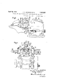
In said drawings the numeral 6 indicates the head or frame of the illustrated machine to support the working parts, which head is carried by a standard 5. At a position convenient to the operator the head carries a horizontal form plate 8 having a U-shaped opening the upper marginal portions 9 of which are inclined to the horizontal and form a concave portion of the plate.
Arranged for movementin a vertical hearing 12 we provide a plunger 60 whichiscarried on a stem 61 and by movement of which plunger in the vertical direction downwardly the central part of the heel end of a sole placed on the form plate 8 will be bulged throughtheopening therein, and the bulgedthrough portion may be in part severed from the sole by a: skiving knife 26 arranged for movement below the plate 8 in suitable guideways. 1' Y Surrounding the vertical spindle 61 we provide a sleeve64 the lowerend 'of which sleeve carries presser feet 66, 68, having inclined lower faces 70, 72, respectively, the inclination of said plates being similar to that of the marginal inclined faces 9 of the form plate 8. Interposed between the sleeve 64 and a collar 62 on the spindle 61 is a spring 7 6 that tends to press the presser feet 66, 68, downwards towards the inclined faces 9 of the form plate, the downward movement of said presser feet being limited by a shoulder 69 on the sleeve 64 engaging against the forwardly projecting part of the plunger 60. While the term plunger has been appliedto the portion of the machine identified by reference numeral 60, itwill'beclear that the presser feet 66, 68, together with the plunger 60, serve to distort the sole and may be considered jointly as a plunger.
Arranged for movement in the plane of the 'skiving knife .26 in the direction transversely of the machine we provide cutters such for example as 50 which are arranged for movement from the opposite sides of the machine towards the centre and are intended for J: severing the marginal portion from the shoe sole;
The foregoing ate as follows I When the heel end of a shoe sole has been arts are arran ed to 0 erv i b placed on the form plate 8 the operator by depressing a treadle will depress the plunger 60 and with the plunger will move the presser feet 66, 68. The plunger and pressers will move until the pressers firmly hold the marginal portions of-the sole against the inclined In this position the pressers 66, 68, will very firmly hold the marginal portion of the sole against the inclined faces so that they cannot become displaced when thesevering cutters 50 are actuated.
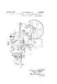
m- Foroperating the plunger 60 and pressers 66, 68, we provide a treadle lever (not shown) that we connect by a rod let to one end of a rocking lever 15 carried on the pivot pin 16 in the upper part of the frame or head. The forward end of said rocking lever is con nected by a link 18 to the rear end of a second rocking lever 19 which is supported for rocking movement on a pivot pin 20, the forward endof which rocking lever19 has a rounded head 21that engages against the upper end of the spindle 61 and by which the plunger and presser feet'may be actuated .as already described. The plunger 60 is normally held raised'some distance above-the form plate 8 by a spring 13 and may be lowered by depression of the rod 14.
We provide an adjustable stop pin 22 on the rocking lever 15'to engage against a block 23'on the head of'the machine, by'which stop the extent of downward movement of the plunger may be limited as may be desirable according to the thickness of the shoe sole to be operated on.
For the purposeof operating the severing cutters 50 we provide the following 1neans:-
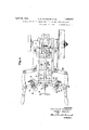
Secured to the front of the head 6' we provide two brackets 30, 31, one on each side of the form plate 8 and of the plunger. Each bracket is provided with an arcuate slot 32 through which projects a bolt 33 that carries a bearing 34'for a sleeve-like member '35. The bearing 34 is adapted to be.
clamped by a clamping screw 37 so-as'fir mly to grip the member 35. Passing through the member is a spindle 39 which at its outer end is pivotally secured to a lever 42 which is at its rear end'connected by a link 43 to the machine head and at its front end is provided with a handle-l5. Secured to the spindle 39 by its shank48 is a severing cutter 50 the lower extremityof the cutting edge of which is in the plane (substantially) of the upper face of the skiving knife and the shank 48 engages in a slot in the sleeve member 35 so that the spindle 39 and severing cutter 50 are adapted to be moved in the direction axially of the spindle; By adjusting the position of the sleeve like member 35 about its axis the angular position of the severing. cutter may be set so that when the handle lever 42 is actuated the severing cutter 50 will sever the leg on one si'deof the U-shaped trimming '(of course the corresponding cutter 50 on the other side will be instrumental in severing the other'leg). If there is adhering a thin layer or flap it will be merely necessary to move the severing cutters 5 0 until they reach the longitudinal median line of the sole when the said flap and the legs of the U-shaped marginal portion will both or all have been severed so to be completely detached from the sole. If there is no flap as aforesaid left attached to the sole, on the completion of the severing cuts by the cutters 50 the sole will merely have a shoulder at each side. If however a thin flap was left adhering to the upper face of the sole then, when the cutters 50 have been operated, they will not only form shoulders on each side but a shallow one across the face of the sole also. lVhether the shoulders will be undercut or not depends upon the adjustment of the parts as already described. It has been pointed out that some heels have a concave breast face (viewed in plan) and therefore it is desirable to cut the shoulders not at right angles to the longitudinal median line of the sole (which would be suitablefor heels having a fiat breast face) but at some less angle according to the shape of the heels to be attached to the shoes and for this purpose the operator will slacken back the screw and adjust the bearing along the arcuate slot and again clamp the parts in adjusted position.
In order to insure accurate positioning of the shoe there are provided two gauges 53, 5-1, against which the heel end of the shoe is engaged. The former of these engages the heel end so as to determine the position thereof laterally and the other, 54, to determine the position longitudinally of the shoe. The gauge 53 is yieldingly supported so that the workman when he has engaged the heel end of the shoe therein can push this back until the shoe engages against the gauge 54. There is preferably also a gauge 56 against which the operator holds the forepart of the shoe and this gauge is carried on a pivot 57 on lugs 58 so that the operator may lift the gauge and swing it out of the way if and when he does not require to use it. All the gauges are adjustable.
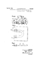
Secured to the form plate and having their longitudinal median line in substantial align ment with the outer edge of the tapering marginal portion of the form plate, we socure stitch severing cutters 80, the upper surfaces of which may be flush with the underside of the form plate and the lower frontparts of which are chamfered off. The cutters may be adjustable either in the plane of or in the plane perpendicular to the under face of the form plate and their cutting edges may be in alignment or at an angle to each other. They may also be adapted for adjustment forwardly and backwardljy of the plate so that they may be adjusted to suit different sizes of shoes. They will be made wide enough so that they will serve the purpose described for several sizes of shoes without requiring adjustment. Although the severing cutters are illustrated as being clamped to the form plate in order to effect the above-mentioned adjustment, it is clear that these cutters may if desired be formed integral with the form plate and hay constitute parts thereof.
What we claim is 'l. A heel scat fitting machine having, in
combination, a form plate having an opening,
a plunger arranged for movement relatively to the form plate to press a portion of a sole through sald openmg, and a presser foot carried by the plunger and moved with it into i to form a heel seat on the heel end of a shoe sole attached by stitches to the shoe at the:
forepart and wa st, and means carried by the form plate to sever any excess stitches securing the sole to the shoe.
3. For a machine of the class defined,in combination, means to form a heel seat on the heel end of a shoe sole attached by stitches to the shoe, means to sever the loose marginal portion producedwhenthe heel seat is formed, and means to sever excess stitches. a a
4. For a machine of theclass defined, in combination, a form plate to receivetheheel end of a shoe sole secured by stitches to the shoe, meansto determine the position of the shoe and. the sole thereon in relation to the form plate, and means to sever excess stitches as the shoe with the .sole thereon is moved into position on the form plate.
5. A machine ofthe class described having, in combination, a slotted form plate, in clined surfaces on the form plate adjacent to the slot, a plunger, a presserfoot carried by the plunger and movable relatively thereto and having similarly inclined work engaging surfaces, a skivingcutter arranged for movementin the direction, longitudinally of the form plate, and two independentlymovable severing cutters arranged for movement from opposite sides and transversely with respect to said form plate.
6.,A machine for forming heel seats on shoe soles having, in comb nation, a slotted form plate to receive the heel end of ashoe sole,means to hold the marginal portion of the sole againstthe form plate, a plunger to bulge the central part of said. sole through the slot in the form plate, a skiving knife to cut into the portion of the sole projecting through the slot inthe form plate, and adjustable cutters to sever the marginal portion from the sole. i
7. A machine for forming heel seats on shoe soles, having in comb nation a slotted form plate provided on its upper face with inclined surfaces to receive the marginal portion of the heel end of a shoe sole, a presser footformed with work engaging surfaces inclined coincidently with the said surfaces, means to actuate the presser foot to hold the said marginal portion of the shoe sole against the inclined surfaceson the form plate, a
plunger arranged for movement'when the said marginal portionis held to force the central part of the sole through the slotted form plate,- and a skiving cutter and two severing cutters all arranged" for movement in the plane ofthe lower face of'the' form plate.
8. A constructional form ofthe machine claimed in claim 7 in'whichthe severing cutters are adjustable to form shoulders either square toor inclined to the plane of the sole.
. '9. A machine for forming heel seats on' shoe soles having in combination, a slotted form plate, a plunger provided with a stem, a collaron' said stem, a sleevemoun-ted slida'bly on said stem and provided with a presser foot, a: bearing to receive the collar and the sleeve, and a spring interposed between said collar and said sleeve. r
10. For a machine of the class defined, in combination, means to grip the marginal portion of the heel end of'a shoe sole, means thereafter-operative to' deform said heel end,
and means operative during the deformingoperation to increase the ginal portion of the sole.
11. A machine for operating on shoe soles having means to 'grip the marginal portion offthe heel end of the sole, means thereafter operative to deform the sole, means to split the deformed sole, and means to sever a marginal strip from the sole;
12. For a machine of the class defined, in combination, a form-platehaving an opening and an inclined: upper face adjacent to theopening, a plunger adapted to pass freely through the opening, and a presserfoot carriedby and movable relatively to said plunger and having a work engaging face shaped to fit into the inclined upper face of the formlate.
13. A heel seat fitting machine having, in combination, a slotted form plate for receiving the heel end of a sole attached to a shoe, a plunger mounted for movement toward and away from saidplate,-said plunger comprising marginal and central portions mounted for movement 'relativelyto each other, one of said portions being constructed and arranged for cooperation with the form plate to grip the sole, and the other of said portins" being constructed and-arranged to cooperate with the form plate to distort the sole while the soleis thus gripped.
14:. A heel seat fitting machine having, in
grip on the marcombination, a slotted form plate for receiving the heel end of a sole, a plunger mounted for movement toward and away from said plate and comprising marginal and central portions mounted for movement together and also mounted for movement relatively to each other, one of said portions-being constructed and arranged to cooperate with the other portion'and also to cooperate with the form plate to distort the sole and to grip the same as the plunger moves toward the form plate, and
the other portion being constructed and ar ranged to distort the sole while the sole is:
gripped between the form plate and the other said portion when said relatively to each other.
15. A heel seat fitting machine having, in combination, a slotted form plate for receiving the heel end of a sole attached'to a shoe,
a plunger mounted for movement toward and" away from said plate,.said plunger comprismg marginal; and central portions construct ed and arranged for movement relatively to,
each other, one of said portionsbeingconstructed and arranged for cooperation with the form plate to: grip the sole and the other of said portionszbeing constructed: and arranged to cooperate with the form plate to.
distort the sole while the soleis thus gripped and to cause a portion of the so-leto project beyond said plate, and a knife mounted for movement with reference to the plate and constructed and arranged to. severisaid portion of the "sole projecting beyond the plate lengthwise of the sole to form'upon the sole a heel seat, shaped forreception by an attaching face of a heel which is to be attached tothe shoe. 1 16; A heel seat fitting machinehaving, in combination, a slotted form plate for receiving the-heel endof a sole attached to a shoe,
said portion during said relative movement between said portions and to cause parto'f the sole to project beyond said plate, and a knife mounted for movement relatively to the plate and constructed and arranged to sever said part of the sole extending beyond the plate lengthwise of the sole to form a heel seat which is shaped for receiving an attach ing face of a heel. i V
17. A heel seat fitting machine having, in combination, a plate provided with a concave portion having a slot at its central part, a plunger mounted for movement toward and away from the plate and comprising a mar ginal portion having a convex portion of a shape complemental to the concave portion of said plate and comprising a central portion movable relatively to said marginal portion, said marginal portion of the plunger being constructed and arranged for cooperating with the concave portion ofthe plate to distort thesole-and to clamp the same in position portions are moved lite to be trimmed, and the central portion of the plunger being constructed and arranged upon movement relatively to the plate and relatively to the marginal portion further to distort the sole while it is gripped between the marginal portion and the plate in order to depress the sole beyond the surface of the plate.
18. A heel seat fitting machine having, in combination, a plate provided with a concave portion having a slot at its central part, a plunger mounted for movement toward and away from the plate and comprising a marginal portion having a convex portion of a shape complemental to the concave portion of said plate and comprising a central portion movable relatively to said marginal por tion, said marginal portion being constructed and arranged to cooperate with the concave portion of the plate to distort the sole and to clamp the same in position to be trimmed, and the central portion being constructed and arranged upon movement toward the plate and relatively to the marginal portion of the plunger further to distort the sole while it is gripped between the marginal portion of the plunger and the plate in order to depress the sole beyond a surface of the plate, and a knife mounted for movement relatively to the plate to trim a portion of the sole extending beyond said surface plate for shaping the heel portion of the sole to receive an attaching face of the heel.
19. A heel seat fitting machine having, in combination, a slotted form plate for receiving the heel end of a sole attached to a shoe, a plunger mounted for movement toward and away from said plate, said plunger comprising marginal and central portions mounted for movement relatively to each other, and resilient means for normally positioning the marginal and the central portions in a pre determined relation with reference to each other and for permitting relative movement between said portions, one of said portions being constructed and arranged for cooperation with the form plate to grip the sole upon the form plate and the other of said portions being constructed and arranged to cooperate with the form plate to distort the sole while the sole is thus gripped.
20. A heel seat fitting machine having, in combination, a plate arranged to be received between the loose heel seat portion of the sole of a shoe and the over-lasted margin of the counter portion of the upper and the insole of the shoe to the shank and the forepart of which the sole is attached, and constructed and arranged to support the rear portion of the sole, and a cutter constructed and arranged to trim the sole positioned upon and supported by the plate to fit the sole for re ceiving the attaching face of a heel which is to be applied to the shoe, said plate having a cutting edge constructed and arranged to sever means b which the sole is attached to the shoe in or er to permit the sole to be positioned upon the plate relatively to the cutter. 21. A heel seat fitting machine having, in combination, a plate arranged to be received between the loose heel seat portion of the sole of a shoe and the over-lasted margin of the counter portion of the upper and the insole of the shoe, to the shank and forepart of which the shoe is attached, and constructed to support the rear portion of the sole, a back gage, and a cutter constructed and arranged to trim the sole positioned upon and supported by the plate to lit the sole for receiving the attaching face of a heel which is to be applied to the shoe, said plate having a cutting edge constructed and arranged to sever stitches by which the sole is attached to the shoe in order to permit the sole to be moved upon the plate until the rear portion of the shoe upper engages the back gage, accurately to position the sole relatively to the cutter.
22. A heel seat fitting machine having, in combination, a plate constructed and er ranged for insertion between the rear portion of a sole stitched to a shoe upper and the shoe upper and to support the rear portion of the sole, said plate having a horseshoeshaped slot through which the sole may be forced and a cutting edge projecting beyond the ends of the slot and constructed and arranged to sever the stitches by which the sole is attached to the shoe upper forwardly of the ends of the slot in order to facilitate the forcing of the sole through the slot, means constructed and arranged to force a portion of the sole through the slot, and means for trimming the rear portion of the sole when the sole has been forced through the plate to fit the sole for receiving a heel.
CHARLES MARTIN BAGSHAW. WALTER WARDLE.
Applications Claiming Priority (1)
| Application Number | Priority Date | Filing Date | Title |
|---|---|---|---|
| GB1856057X | 1926-04-14 |
Publications (1)
| Publication Number | Publication Date |
|---|---|
| US1856057A true US1856057A (en) | 1932-04-26 |
Family
ID=10892092
Family Applications (1)
| Application Number | Title | Priority Date | Filing Date |
|---|---|---|---|
| US182676A Expired - Lifetime US1856057A (en) | 1926-04-14 | 1927-04-11 | Machine for use in forming heel seats on boot and shoe soles |
Country Status (1)
| Country | Link |
|---|---|
| US (1) | US1856057A (en) |
-
1927
- 1927-04-11 US US182676A patent/US1856057A/en not_active Expired - Lifetime
Similar Documents
| Publication | Publication Date | Title |
|---|---|---|
| US2330273A (en) | Manufacture of sandals | |
| US1856057A (en) | Machine for use in forming heel seats on boot and shoe soles | |
| US1980371A (en) | Heel-seat fitting machine | |
| US2635263A (en) | Machine for operating upon insoles | |
| US2134100A (en) | Sole machine | |
| US1698902A (en) | Machine for operating upon the heel ends of boots and shoes | |
| US2133372A (en) | Heel-attaching machine | |
| US2009553A (en) | Machine for trimming and molding heel covers | |
| US1307284A (en) | Heel-seat-forming machine | |
| US2190784A (en) | Heel-seat fitting machine | |
| US2690574A (en) | Machine for operating upon soles | |
| US1747285A (en) | Method of and machine for operating upon the soles of boots or shoes | |
| US2291630A (en) | Method and means for use in positioning shoes | |
| US1979386A (en) | Heel-seat fitting machine | |
| US1963209A (en) | Heel-seat-fitting machine | |
| US2082862A (en) | Locating device | |
| US2017151A (en) | Skiving machine | |
| US1743482A (en) | Heel-seat-fitting machine | |
| US1612213A (en) | Shoe machine | |
| US1882077A (en) | Heel breast flap laying and flap trimming machine | |
| US2048671A (en) | Heel-seat fitting machine | |
| US1742503A (en) | Heel-seat fitting machine | |
| US1138584A (en) | Apparatus for use in the manufacture of boots and shoes. | |
| US1783212A (en) | Heel-seat-fitting machine | |
| US212357A (en) | Improvement in cutting-in boot-fronts |