US1855099A - Stop motion for knitting machines - Google Patents
Stop motion for knitting machines Download PDFInfo
- Publication number
- US1855099A US1855099A US442901A US44290130A US1855099A US 1855099 A US1855099 A US 1855099A US 442901 A US442901 A US 442901A US 44290130 A US44290130 A US 44290130A US 1855099 A US1855099 A US 1855099A
- Authority
- US
- United States
- Prior art keywords
- casing
- stop motion
- arms
- threads
- thread
- Prior art date
- Legal status (The legal status is an assumption and is not a legal conclusion. Google has not performed a legal analysis and makes no representation as to the accuracy of the status listed.)
- Expired - Lifetime
Links
Images
Classifications
-
- D—TEXTILES; PAPER
- D04—BRAIDING; LACE-MAKING; KNITTING; TRIMMINGS; NON-WOVEN FABRICS
- D04B—KNITTING
- D04B35/00—Details of, or auxiliary devices incorporated in, knitting machines, not otherwise provided for
- D04B35/10—Indicating, warning, or safety devices, e.g. stop motions
Definitions
- This invention relates to knitting machine :stop motion of the samelgeneral 'character'as that shown and described ina 'prior U. S. apatent to Frank Crawtord No. 510529,
- the stop motion comprises a substantially "circular casng from which radially extends aplu rality of'arms, one tor :the supportof each of the threads to ⁇ he controlled.
- On the oluter 'end of'each thread-suporting :arm is a.
- each of the inner thread guides lis a slack deteotor through 'which the thread runs.
- the slaok -detecter is operatively assocated *with the trip-rods, above noted, ⁇ and functions to actuate the trip-'red ifabnormal slack occurs'in the thread, or .if the thread breaks.
- the diameter of the easing limits the number of 'arms which may :eX- tend therefrom and to increase :the diameter of the casing to accommodate :more sarms would necessari'ly require .the ,incneas-ing of the diameter of the actuating disc wi-thinthe casng -to take care of the 'eonseq uen-t instopmoti'on units,eachxofwhieh embodies t-he essential elements shown and describedathe said prior ;patent to Frank Crawford;
- the lower casing 1 comprises a bottom plate 3 and a vertically eX- tending peripheral flange 4:, providing a housing for the Operating parts of an independent stop motion mechanism, notshown in the present application, but which as above noted, is substantially the same as that shown in thesaid prior patent to Frank Crawford.
- the upper casing ⁇ 2 of each stop motion unit comprises a bottom plate 5 anda vertically extending peripheral fiange 6.
- the bottom plate 5 of the upper casing 2 in each instance, is provided with an annular shoulder 7 adapted to receive the upper edge of the -peripheral flange 4 of the lower casing 1 of the corresponding unit, to maintain aXial alignment between the upper and lower'casings of each stop motion unit.
- bottom plate 3 of the lower 'casing 1 of the upper unit A is provided with an annular shoulder 8, adapted to receive the peripheral fiange 6 otthe upper casing 2 of the lower unit v
- the vertical fiange or wall 6 of the upper casing 2 ofeach unit is provided with a horizontally ext ending flange 9, to each of which, in the'present instance, is Secured or forned integral with, a series of radially eXtending thread-supporting arms 10, 10.
- the inner end of the rock-shaft 11 is mounted in a hearing 12 formed in the vertical wall 6 of the casing 2.
- the outer 'end of the rock-shaft 11 ismounted in a bearing 13 Secured to the. outer end of the arm 10. ;Adjacentuthe bearng 13, the rock-shaft 411 is provided withan arm14 *which is adapted to be engaged by one arm 15 of an outer thread guide 16.
- the outer thread guide 16 is pivotally 'mounted at 17 tothe outer-?end of the wall 6 of the upper casng 2, each rock-shaft 11 is provided with an inner thread-guide 20.
- the arms 10 is a grid-'like structure 21 having horizontally eX- tending bars 22, 23 and 24.
- trip-rod 25 Pvotally mounted in and eXtending radially from each of the lower casings l of the units A and A respectively is a series of horizontally disposed trip-rods 25, there being one trp-rod for each of the radially eX- tending arms 10.
- Each trip-rod 25 is rotatably mounted in a bearing 26 formed in the vertical ⁇ wall 4 of the lower casing 1 of each unit and 'adjacent its inner end the triprod is mounted in a hearing 27 for-med in a vertically extending lug or rib 28 which-prop jects upwardly from and, in the present instance, is formed integral withthe base plate ofthe lower casing 1.
- each of the trip rods'25 is provided with an ⁇ arm 29.
- the r arm 29 is adapted to cooperate with the'actuating disc of the stop motion unit, which is not shown in the present application but which corresponds substantally with that the outer thread guides 16 ot the arms 10, the said threads passing through the throats '19 of the outer thread guides 16, then substantially parallel to the arms 10 and over the wardly to one side'of the bars 22, 23and' 2& of the grid structures 21 to 'the thread guides which are adapted to feed ?that particular 'cated substantially in vertical alignment with i hook-like inner thread guides 20, then downthread to the needles of the knittingmachine with which the stop motion is associated.
- the threads in passing downwarly from the inner thread guides 20-of the rock-shafts i 11 pass between the bars of the grid structures 21 andthe laterally extending arms 31 and 32 of the drop wres 30, in each instance, and'thereby maintains the trip-rods 25 re-- spectively associated with the drop-wires 30 in normal ineffective positions.
- the arms 10 of each unit are spaced merely a suflicient distance apart to provide working clearance for the individual elements associated with each arm within the casings of the stop motion unit-s and immediately adjacent the outside thereof.
- I In order to increase the number of threads capable of being handled by the stop motion as a whole or unitary device, I , provide two or more separate units arranged in superposed axially aligned relation to each other and in such a manner with respect to each other that the arms 10 of the upper unit are disposed above the spaces formed between the arms 10 of the lower unit.
- the threads 50 supported by the arms of the upper unit are substantially equidistantly and angularly spaced from the threads w which are supported by the arms of the lower unit, each thread thereby being assigned a definite Vertical plane of operation.
- the outer walls 4 and 6 of the casings 1 and 2 of the upper unit A are of a relatively larger diameter than the corresponding walls of the lower unit A, thus providing an overhang or step, such as indicated at 35 in the unitary stop motion casng formed by the casngs of the units A and A
- the inner thread guides 20 and the grid structures 21 of the upper unit A are disposed a greater distance from the aXis of the stop motion than are the corresponding thread guides 20 and grid structures 21 of the lower unit A.
- Each of the stop motion units is provided with a slide'R of the same character as shown in the said U. patent which is actuated through the medium of the actuating disc to move radially inward when one of the 'triprods 25 .is actuated to efiect the stopping of the knitting machine to which the stop motion is connected.
- a common machine control element is provided inthe form of a vertically disposed shaft 40, for stopping the machine when either ofthe stop motions is actuated.
- This control element 40 is provided with an arm 41 adjacent the bottom of each of the respective units A and A each arm 41 being provided with a vertically extending pin 42 which projects into an elongated slot 43 formed in the respective oper ating slide R.
- the lower end of the shaft 40 may be con nected in any suitable manner, within the skill of an ordinary mechanic so that rocking of the shaft 40 about its vertical aXis in the man ner noted ⁇ will efi ect the stoppng of the linitting machine to which the apparatus is applied., i
- a stop motion comprising' a series -of radially extending 'thread-supporting arms, a second series of radially extending arms vertically and relatively closely'spaced and with respect to the first said series with .the I 2.
- the inner thread guides'of the one series of arns being spaced radally with respect to the inner thread guides 'of'the other series of arms for respectively supporting different individual threads in close order.
- a stopmotion comprising acasing, a series of thread-supporting arms extending radially from said casing, and asecond series of thread-supporting arms extending' radally from said casing in- ⁇ relativelyclose vertical and angular spaced relationto the; arms of the first said series.
- a stopmotion compri'singa casing, a se ries of thread-supportingarms extending radially from said casin'g, a secondseries of thread-supporting arms extending radially from said casing in relatively close verticaland angular spaced relation to the arms of the first said series, a stop motionmechanism controlled by the threads supported by the first said series of arms, and an independent stop motion mechanism controlled by the:
- a stop motion comprising acasing, a series of thread-supportingarms extendng radally from 'said casing a second series of .thread-supporting armsiextending radially from said casing in relatively close vertical and angular spaced relation to'the. arms of the 'first said series, a 'stop motion mechansm i controlled by the threads supported by the first said series of arms, an independent stop motion mechanism controlled by the threads supported by the second said series. of arms, a Q machine-controlling ,element common v to both said stop motion mechanismgand means connecting each stop motion mechanism to' mmm;
- a stop motion comprising a cylindrical i? casingof stepped formation, 'the upper portion being'of a relativelylarger diameter than the lower portion thereof, a series of threadsupporting arms extending radially from the larger portion of thejcasing, a series' of threadsupporting arms extendingradially from the smaller portion of the casing' in angular spaced relation to the arms of the larger portion, a thread guide at the outer end of each arm, and a thread guide at the inner end of each arm adjacent the wall of the casing porr tion from' which the arm extends, providing vertical, angular and radial spacing of the inner thread guides in successive order around the casing.
- a stop motion comprising a cylindrical casing of stepped formation, the upperportion being ofa relatively larger diameter than the lower portion thereof, a series of threadfrom the smaller portion of the casng in angular spaced relation to the arms of the larger portion, a thread guide at the outer end of each arm, a thread guide at the inner end of each arm adjacent the wall of the casing porr tion from which the arm extends, providing vertical, angular and radial spacing of the inner thread guides in successive order around the' casing, and an independent stop motion mechanism in each of the said portions, of the casing and adapted to be controlled respectively by the threads supported by' the arms extending from the respective casing portions.
- a stop motion conprisinga cylindrical casing of stepped formation, the upperportionbeing of a relatively larger diameter than thelovver portion thereof, a series of threadsupporting arms extendingradially from the larger portion of the casing, a series of threadsupporting arms extending radially'from the smaller portion of the casing in angular spaced relation to the arms of the larger portion, a thread guideat 'the outer end of each arm, a thread guide "at the inner end of each arm adjacent the'wall of the :casing portion from which the 'arm extenda providing'vertical, angular and-radialspacing of the inner i thread guides in, successive order around the casing, 'an independent stop motion' mechanism in each of the said 'portions of the casing and adapted to be controlled respectivel-y erable by either thereof independent of .the
Landscapes
- Engineering & Computer Science (AREA)
- Textile Engineering (AREA)
- Knitting Machines (AREA)
Description
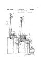
-Aprl 19, 1932.` A. CRAWFORD STOP MOTIAON FOR KNITTING MACHINES Filed April 9, 1930 2 Sheets-Sheet l April 19, 1932. A. CRAWFORD STOP MOTION FOR KNITTING MACHI NES Filed April 9, 1930 2 Sheets-Sheet Patented Apr. 19, 1932 UNITED ;STATES `i ATENT OFFlCE- ALF-RED GRAWFORD, OF NEW BRUNSWICK, JERSEY, -ASSIGNOR TO CRAWEORED MANUFACTURING COMPANY, OF NEWBRUNSWICK, NEW JERSEY, A CORPOBATION OF NEW J' ERSE'Y s'ror MOTION ron KNITTING MACHINES Application filed Apri1'9 1930. Serial No. 4423901.
This invention relates to knitting machine :stop motion of the samelgeneral 'character'as that shown and described ina 'prior U. S. apatent to Frank Crawtord No. 510529,
' to all the :knitting threadsand adaptedto be actuated by `one -or more of the threads, to stop ;the knitting machine, .if certain abnormal 'conditions arose in any one of the threads, ,or in two or more of the threads simultaneously. Obviously, :this ;general type of stop motion is capable 'of handling more or less than'eight ends'with equal effectiveness.
Recent developments in ,the lmitting 'art require the handling of extremely large numbers of threads, for example from ,to ends. Structural limitations such as necessary Operating clearances, .increased inert ia of 'enlarged and multiplied parts, z'etc., and the touling of closely positioned threads have made .the use 'of a single stop motion,
common .to all such threads, practical ly im possible, in the machines employing such a large number of threads.
As shown in the said pri'or patent 'each of the threads ,Controls an individual trip-;rod and the entire number of trip-rods control, and also are *controlled by, an actuating *disc which is common .to "all the trip-rods. To
provide a common `actuating disc for the large number of trip-rods necessary to control the large number `of individual threads, above noted, would necesstate the making of the 'actuating disc of :a relatively ,large i size and heavy Construction, which would increase the nerta of'ths 'essental element 'co-such an extent that the'sensitveness of the device would `be materially'afiected, making the -actuation of the disc sluggish, and practicaliy impossible 'byany single 'one of the trip-rods, should an abnormal conditionarise' in; the ;thread controlling such trip-rod.
As shown in the said prior patent, the stop motion comprises a substantially "circular casng from which radially extends aplu rality of'arms, one tor :the supportof each of the threads to `he controlled. Each of the radially extending thread=supportng arms is providedwth an nner thread guide lo+ cated adjacen't 'the .wall :of the casing :and carried by :a "rock shaft which :extends :inwardly toward the icen ter of the 'casing On the oluter 'end of'each thread-suporting :arm is a. piuotal ly mounted thread `'guide which co-operates with an .arm en the rock shaift to rock said 'shaft and ;release 'the thread &rom the innerrthread guide thereen when abnormal tension is `applied 'to the thread. I
Below each of the inner thread guides lis a slack deteotor through 'which the thread runs. The slaok -detecter is operatively assocated *with the trip-rods, above noted, `and functions to actuate the trip-'red ifabnormal slack occurs'in the thread, or .if the thread breaks.
Obviously, the diameter of the easing limits the number of 'arms which may :eX- tend therefrom and to increase :the diameter of the casing to accommodate :more sarms Would necessari'ly require .the ,incneas-ing of the diameter of the actuating disc wi-thinthe casng -to take care of the 'eonseq uen-t instopmoti'on units,eachxofwhieh embodies t-he essential elements shown and describedathe said prior ;patent to Frank Crawford;
In order to prevent ta-ngling 'of the various series of 'threads controlled by the ,respective stop motion units I :have increased ?the 'di-ram:-
eter of the ;casing of 'the 'upper stop motion unit so' thatthe casing oi" the 'said upperimit' overhangs that of theilower unit, th'ereby pro-1 ducing in the :aggregate a unitary stop'imm tion casing oi: stopped formation, and I'have arranged :the ra'dially extendingarms 'of the A and A comprises a lower casing l, and an" upper casing .2. The lower casing 1 comprises a bottom plate 3 and a vertically eX- tending peripheral flange 4:, providing a housing for the Operating parts of an independent stop motion mechanism, notshown in the present application, but which as above noted, is substantially the same as that shown in thesaid prior patent to Frank Crawford.
The upper casing`2 of each stop motion unit, comprises a bottom plate 5 anda vertically extending peripheral fiange 6. The bottom plate 5 of the upper casing 2, in each instance, is provided with an annular shoulder 7 adapted to receive the upper edge of the -peripheral flange 4 of the lower casing 1 of the corresponding unit, to maintain aXial alignment between the upper and lower'casings of each stop motion unit. v
i In order to maintain axial alignment between' the double casing 1-2 ofthe lower unit A and the double casing l--2 of the upper unit A the, bottom plate 3 of the lower 'casing 1 of the upper unit A is provided with an annular shoulder 8, adapted to receive the peripheral fiange 6 otthe upper casing 2 of the lower unit v The vertical fiange or wall 6 of the upper casing 2 ofeach unit is provided with a horizontally ext ending flange 9, to each of which, in the'present instance, is Secured or forned integral with, a series of radially eXtending thread-supporting arms 10, 10. One-ach of the arms lOis pivotal'ly mounti ed a rock-shaft 11, the inner end of which eX- tends into the upper casing 2 of the stop motion unit and therein co-operates with tension regulating mechanism, not shown in the present application but which s similar in charr acter to that shown in the said prior U. S.
patent. v r
The inner end of the rock-shaft 11 is mounted in a hearing 12 formed in the vertical wall 6 of the casing 2. `The outer 'end of the rock-shaft 11 ismounted in a bearing 13 Secured to the. outer end of the arm 10. ;Adjacentuthe bearng 13, the rock-shaft 411 is provided withan arm14 *which is adapted to be engaged by one arm 15 of an outer thread guide 16. The outer thread guide 16 is pivotally 'mounted at 17 tothe outer-?end of the wall 6 of the upper casng 2, each rock-shaft 11 is provided with an inner thread-guide 20.
Depending from each of: the arms 10 is a grid-'like structure 21 having horizontally eX- tending bars 22, 23 and 24.
Pvotally mounted in and eXtending radially from each of the lower casings l of the units A and A respectively is a series of horizontally disposed trip-rods 25, there being one trp-rod for each of the radially eX- tending arms 10. Each trip-rod 25 is rotatably mounted in a bearing 26 formed in the vertical` wall 4 of the lower casing 1 of each unit and 'adjacent its inner end the triprod is mounted in a hearing 27 for-med in a vertically extending lug or rib 28 which-prop jects upwardly from and, in the present instance, is formed integral withthe base plate ofthe lower casing 1. i
'Inside the circular rib- 28, each of the trip rods'25 is provided with an` arm 29. The r arm 29 is adapted to cooperate with the'actuating disc of the stop motion unit, which is not shown in the present application but which corresponds substantally with that the outer thread guides 16 ot the arms 10, the said threads passing through the throats '19 of the outer thread guides 16, then substantially parallel to the arms 10 and over the wardly to one side'of the bars 22, 23and' 2& of the grid structures 21 to 'the thread guides which are adapted to feed ?that particular 'cated substantially in vertical alignment with i hook-like inner thread guides 20, then downthread to the needles of the knittingmachine with which the stop motion is associated.
The threads in passing downwarly from the inner thread guides 20-of the rock-shafts i 11 pass between the bars of the grid structures 21 andthe laterally extending arms 31 and 32 of the drop wres 30, in each instance, and'thereby maintains the trip-rods 25 re-- spectively associated with the drop-wires 30 in normal ineffective positions.
The Construction and operation thus far described is substantially the same as that of the aforesaid'prior patent, insofar as each of the individual and independent stop motion Ne units is concerned.
. In order to provide for a maximum number of threads to be handled by each unit of the stop motion,.the arms 10 of each unit are spaced merely a suflicient distance apart to provide working clearance for the individual elements associated with each arm within the casings of the stop motion unit-s and immediately adjacent the outside thereof.
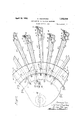
In order to increase the number of threads capable of being handled by the stop motion as a whole or unitary device, I ,provide two or more separate units arranged in superposed axially aligned relation to each other and in such a manner with respect to each other that the arms 10 of the upper unit are disposed above the spaces formed between the arms 10 of the lower unit. Thus, the threads 50 supported by the arms of the upper unit are substantially equidistantly and angularly spaced from the threads w which are supported by the arms of the lower unit, each thread thereby being assigned a definite Vertical plane of operation.
In order to avoid tangling of the threads 00 of the upper unit with the threads m of the lower unit at the points immediately adjacent the stop motion casing, where the said relative spacing of the threads is naturally closer than at the outer ends of the arms 10, the outer walls 4 and 6 of the casings 1 and 2 of the upper unit A are of a relatively larger diameter than the corresponding walls of the lower unit A, thus providing an overhang or step, such as indicated at 35 in the unitary stop motion casng formed by the casngs of the units A and A In this manner the inner thread guides 20 and the grid structures 21 of the upper unit A are disposed a greater distance from the aXis of the stop motion than are the corresponding thread guides 20 and grid structures 21 of the lower unit A. Thus the down runs of the threads w and :13 in addition to their angular circumferential spacing around the periphery of the stop motion casing, are
also radially spaced with respect to each' other, providing a maximum amount of clearance for each thread to avoid its becoming entangled with adjacent threads, this radial spacing of the threads 02 from the threads a; being further accentuated by the threads m engagng the peripheral edge 36 of the horizontal flange 9 of the lower unit A i The vertical spacing of the thread guides 16 and 20 of the superposed units A and A respectively provides vertical spacing of the horizontal runs of the threads w, m
From the above, it will be observed that by employing the mechanism shown and described in the above-mentioned U. S. patent and by superimposing two or more of these units `one above another and by so arranging the units with respect to each other in such a manner that the supporting arms of oneunit lie abovethe spaces between the supporting arms' of the other unit, I may accommod ate an extremely large number of threads without affecting 'the sensitiveness ofthe device, which is characteristic of the device shown in the said prior U. S. patent, and by merely increasing the outer diameter of the casing of the upper unit I provide sufiicient clearance for the threads on their down run to the knitting machine to preventthe threads from becoming entangled one with another.
Each of the stop motion units is provided with a slide'R of the same character as shown in the said U. patent which is actuated through the medium of the actuating disc to move radially inward when one of the 'triprods 25 .is actuated to efiect the stopping of the knitting machine to which the stop motion is connected.` e v In the present nstance, a common machine control element is provided inthe form of a vertically disposed shaft 40, for stopping the machine when either ofthe stop motions is actuated. This control element 40 is provided with an arm 41 adjacent the bottom of each of the respective units A and A each arm 41 being provided with a vertically extending pin 42 which projects into an elongated slot 43 formed in the respective oper ating slide R.
Upon referring to Fig. 2, it will be obvious that when one of the slidesR is moved radially inward by reason of the actuaton of the unit will be free to move within the elongated slot 43 of'the slide R of said unafi ected unit, thereby causing no operation whatsoever of the said unaii'ected unit. i
a The lower end of the shaft 40 may be con nected in any suitable manner, within the skill of an ordinary mechanic so that rocking of the shaft 40 about its vertical aXis in the man ner noted {will efi ect the stoppng of the linitting machine to which the apparatus is applied., i
I claim: e i 1. A stop motion comprising' a series -of radially extending 'thread-supporting arms, a second series of radially extending arms vertically and relatively closely'spaced and with respect to the first said series with .the I 2. A stop motion cmprising a series of i ing inaxialalignment being positoned over the spaces' between the arms of the other' series, providing angular spacng between the alternating arms of the two seres, a thread guide at the outer end 'of'each arm, and a thread gu'ideat the inner end of each arm,
the inner thread guides'of the one series of arns being spaced radally with respect to the inner thread guides 'of'the other series of arms for respectively supporting different individual threads in close order.
3. A stopmotion comprisingacasing, a series of thread-supporting arms extending radially from said casing, and asecond series of thread-supporting arms extending' radally from said casing in-`relativelyclose vertical and angular spaced relationto the; arms of the first said series. i v
4:. A stopmotion compri'singa casing, a se ries of thread-supportingarms extending radially from said casin'g, a secondseries of thread-supporting arms extending radially from said casing in relatively close verticaland angular spaced relation to the arms of the first said series, a stop motionmechanism controlled by the threads supported by the first said series of arms, and an independent stop motion mechanism controlled by the:
threads supported by the second said series of arms;
a and angular spaced relation to the armsof i the first said series,a'stop motion mechanism controlled by the threads supported ,by the,`
first saidseries of arms, an independent stop `motion mechansm controlled by the threads supported by the second 'said seriesof arms,- and' a machine-controlhng element common to bothsaid stop motion mechanisms. i
6. A stop motion comprising acasing, a series of thread-supportingarms extendng radally from 'said casing a second series of .thread-supporting armsiextending radially from said casing in relatively close vertical and angular spaced relation to'the. arms of the 'first said series, a 'stop motion mechansm i controlled by the threads supported by the first said series of arms, an independent stop motion mechanism controlled by the threads supported by the second said series. of arms, a Q machine-controlling ,element common v to both said stop motion mechanismgand means connecting each stop motion mechanism to' mmm;
' independent of the other said stop mo ion' mechansm K 7. A stop motion comprising a cylindrical i? casingof stepped formation, 'the upper portion being'of a relativelylarger diameter than the lower portion thereof, a series of threadsupporting arms extending radially from the larger portion of thejcasing, a series' of threadsupporting arms extendingradially from the smaller portion of the casing' in angular spaced relation to the arms of the larger portion, a thread guide at the outer end of each arm, and a thread guide at the inner end of each arm adjacent the wall of the casing porr tion from' which the arm extends, providing vertical, angular and radial spacing of the inner thread guides in successive order around the casing. i
' 8. A stop motion comprising a cylindrical casing of stepped formation, the upperportion being ofa relatively larger diameter than the lower portion thereof, a series of threadfrom the smaller portion of the casng in angular spaced relation to the arms of the larger portion, a thread guide at the outer end of each arm, a thread guide at the inner end of each arm adjacent the wall of the casing porr tion from which the arm extends, providing vertical, angular and radial spacing of the inner thread guides in successive order around the' casing, and an independent stop motion mechanism in each of the said portions, of the casing and adapted to be controlled respectively by the threads supported by' the arms extending from the respective casing portions. a
9. A stop motion conprisinga cylindrical casing of stepped formation, the upperportionbeing of a relatively larger diameter than thelovver portion thereof, a series of threadsupporting arms extendingradially from the larger portion of the casing, a series of threadsupporting arms extending radially'from the smaller portion of the casing in angular spaced relation to the arms of the larger portion, a thread guideat 'the outer end of each arm,a thread guide "at the inner end of each arm adjacent the'wall of the :casing portion from which the 'arm extenda providing'vertical, angular and-radialspacing of the inner i thread guides in, successive order around the casing, 'an independent stop motion' mechanism in each of the said 'portions of the casing and adapted to be controlled respectivel-y erable by either thereof independent of .the
other thereof. v a ALFRED CRAWFORD;
Priority Applications (1)
| Application Number | Priority Date | Filing Date | Title |
|---|---|---|---|
| US442901A US1855099A (en) | 1930-04-09 | 1930-04-09 | Stop motion for knitting machines |
Applications Claiming Priority (1)
| Application Number | Priority Date | Filing Date | Title |
|---|---|---|---|
| US442901A US1855099A (en) | 1930-04-09 | 1930-04-09 | Stop motion for knitting machines |
Publications (1)
| Publication Number | Publication Date |
|---|---|
| US1855099A true US1855099A (en) | 1932-04-19 |
Family
ID=23758601
Family Applications (1)
| Application Number | Title | Priority Date | Filing Date |
|---|---|---|---|
| US442901A Expired - Lifetime US1855099A (en) | 1930-04-09 | 1930-04-09 | Stop motion for knitting machines |
Country Status (1)
| Country | Link |
|---|---|
| US (1) | US1855099A (en) |
Cited By (1)
| Publication number | Priority date | Publication date | Assignee | Title |
|---|---|---|---|---|
| US20160122914A1 (en) * | 2013-06-21 | 2016-05-05 | Santoni S.P.A. | Thread dispensing element for a thread guide for knitting machines, and thread guide comprising the dispensing element |
-
1930
- 1930-04-09 US US442901A patent/US1855099A/en not_active Expired - Lifetime
Cited By (1)
| Publication number | Priority date | Publication date | Assignee | Title |
|---|---|---|---|---|
| US20160122914A1 (en) * | 2013-06-21 | 2016-05-05 | Santoni S.P.A. | Thread dispensing element for a thread guide for knitting machines, and thread guide comprising the dispensing element |
Similar Documents
| Publication | Publication Date | Title |
|---|---|---|
| US1855099A (en) | Stop motion for knitting machines | |
| US2473944A (en) | Selecting mechanism | |
| US1581093A (en) | Yarn furnishing and controlling mechanism for knitting machines | |
| US668833A (en) | Knitting-machine. | |
| US1115128A (en) | Knitting-machine. | |
| US1593670A (en) | Machine for braiding cord | |
| US2259375A (en) | Clamping and cutting mechanism for circular knitting machines | |
| US1911698A (en) | Pattern mechanism for circular rib knitting machines | |
| US360735A (en) | schroeler | |
| US2422232A (en) | Wrapping mechanism | |
| US1991785A (en) | Stop mechanism for knitting machines | |
| US2039133A (en) | Attachment for knitting machines | |
| US449910A (en) | Stopping mechanism for knitting-machines | |
| US2172114A (en) | Multiple thread back-winding machine | |
| US3168822A (en) | Knitting machine stop motion | |
| US1571294A (en) | Stop mechanism for knitting machines | |
| US535461A (en) | Looping attachment for circular-knitting machines | |
| US1305045A (en) | of new brunswick | |
| US2573261A (en) | Safety stop mechanism for knitting machines | |
| US2184107A (en) | Stop motion for knitting machines | |
| US2590193A (en) | Wrap stripe stop motion | |
| US944921A (en) | Stop-motion for knitting-machines. | |
| US1827715A (en) | Stop mechanism for braiding machines | |
| US1756655A (en) | Thread-controlling mechanism for sewing machines | |
| US1992860A (en) | Stop motion for knitting machines |