US1855098A - Apparatus for molding and curing footwear - Google Patents
Apparatus for molding and curing footwear Download PDFInfo
- Publication number
- US1855098A US1855098A US512434A US51243431A US1855098A US 1855098 A US1855098 A US 1855098A US 512434 A US512434 A US 512434A US 51243431 A US51243431 A US 51243431A US 1855098 A US1855098 A US 1855098A
- Authority
- US
- United States
- Prior art keywords
- mold
- sleeve
- footwear
- molding
- shoe
- Prior art date
- Legal status (The legal status is an assumption and is not a legal conclusion. Google has not performed a legal analysis and makes no representation as to the accuracy of the status listed.)
- Expired - Lifetime
Links
- 238000000465 moulding Methods 0.000 title description 29
- 150000001875 compounds Chemical class 0.000 description 7
- 238000010438 heat treatment Methods 0.000 description 6
- 239000000463 material Substances 0.000 description 6
- 239000002184 metal Substances 0.000 description 4
- 229910052751 metal Inorganic materials 0.000 description 4
- 238000004519 manufacturing process Methods 0.000 description 3
- 238000000034 method Methods 0.000 description 3
- 230000008674 spewing Effects 0.000 description 3
- 230000006835 compression Effects 0.000 description 2
- 238000007906 compression Methods 0.000 description 2
- 238000010276 construction Methods 0.000 description 2
- 239000004744 fabric Substances 0.000 description 2
- 238000004073 vulcanization Methods 0.000 description 2
- 239000010425 asbestos Substances 0.000 description 1
- 239000011324 bead Substances 0.000 description 1
- 230000005484 gravity Effects 0.000 description 1
- 238000011065 in-situ storage Methods 0.000 description 1
- 238000003780 insertion Methods 0.000 description 1
- 230000037431 insertion Effects 0.000 description 1
- 230000009916 joint effect Effects 0.000 description 1
- 239000010985 leather Substances 0.000 description 1
- 238000012423 maintenance Methods 0.000 description 1
- 238000012986 modification Methods 0.000 description 1
- 230000004048 modification Effects 0.000 description 1
- 229920000136 polysorbate Polymers 0.000 description 1
- 229910052895 riebeckite Inorganic materials 0.000 description 1
- 238000007493 shaping process Methods 0.000 description 1
- 238000003466 welding Methods 0.000 description 1
Images


Classifications
-
- B—PERFORMING OPERATIONS; TRANSPORTING
- B29—WORKING OF PLASTICS; WORKING OF SUBSTANCES IN A PLASTIC STATE IN GENERAL
- B29D—PRODUCING PARTICULAR ARTICLES FROM PLASTICS OR FROM SUBSTANCES IN A PLASTIC STATE
- B29D35/00—Producing footwear
- B29D35/0009—Producing footwear by injection moulding; Apparatus therefor
- B29D35/0018—Moulds
-
- B—PERFORMING OPERATIONS; TRANSPORTING
- B29—WORKING OF PLASTICS; WORKING OF SUBSTANCES IN A PLASTIC STATE IN GENERAL
- B29D—PRODUCING PARTICULAR ARTICLES FROM PLASTICS OR FROM SUBSTANCES IN A PLASTIC STATE
- B29D35/00—Producing footwear
- B29D35/0054—Producing footwear by compression moulding, vulcanising or the like; Apparatus therefor
- B29D35/0063—Moulds
-
- B—PERFORMING OPERATIONS; TRANSPORTING
- B29—WORKING OF PLASTICS; WORKING OF SUBSTANCES IN A PLASTIC STATE IN GENERAL
- B29D—PRODUCING PARTICULAR ARTICLES FROM PLASTICS OR FROM SUBSTANCES IN A PLASTIC STATE
- B29D35/00—Producing footwear
- B29D35/02—Producing footwear made in one piece using a moulding technique, e.g. by injection moulding or casting
-
- B—PERFORMING OPERATIONS; TRANSPORTING
- B29—WORKING OF PLASTICS; WORKING OF SUBSTANCES IN A PLASTIC STATE IN GENERAL
- B29C—SHAPING OR JOINING OF PLASTICS; SHAPING OF MATERIAL IN A PLASTIC STATE, NOT OTHERWISE PROVIDED FOR; AFTER-TREATMENT OF THE SHAPED PRODUCTS, e.g. REPAIRING
- B29C35/00—Heating, cooling or curing, e.g. crosslinking or vulcanising; Apparatus therefor
-
- B—PERFORMING OPERATIONS; TRANSPORTING
- B29—WORKING OF PLASTICS; WORKING OF SUBSTANCES IN A PLASTIC STATE IN GENERAL
- B29K—INDEXING SCHEME ASSOCIATED WITH SUBCLASSES B29B, B29C OR B29D, RELATING TO MOULDING MATERIALS OR TO MATERIALS FOR MOULDS, REINFORCEMENTS, FILLERS OR PREFORMED PARTS, e.g. INSERTS
- B29K2021/00—Use of unspecified rubbers as moulding material
Definitions
- This invention relates to an 'improved method of and apparatus for molding footwear composed wholly or partly of rubber or rubber compound, and is particularly applicable to the manufacture of rubber-soled footwear in a heated mold in which the partly prepared footwear is inserted, distended by inflation and cured, and the object is to provide a method and molding apparatus by which a high grade molded and vulcanized product can be produced without the need for the degree of skill required heretofore for this purpose, and whereby a single molding machine of cheap construction may be employed to manufacture footwear of different sizes within a given range.
- a sleeve of flexible material, or partly of rigid and partly of flexible material is employed as a detachable linin for the metal'mold, the interior surface 0 the sleeve being a counter part of the external configuration of the article to be molded, and the external configuration of the sleeve fitting the interior of the mold.
- the mold employed in conjunction with the sleeve or lining is preferably a two-part mold comprising a lower part and an upper hinged part, the line of division following the surface of the welt of the shoe.
- the sleeve would be fitted to the upper art only of the mold, the sides and bottom of the sole and heel being molded by the metallic surface of the lower part of the mold, the Welt and its junction with the upper being molded by the corresponding portions of the sleeve, the rubber to form the sole and heel being roughly plastered on the shoe and the latter, fitted with an inflatable last, being then placed with the surrounding sleeve within the mold and the rubber or rubber compound shaped, and vulcanized by heat.
- the sleeve above referred to is adapted to be fitted around the shoe before it is placed in the mold, such sleeve serving to prevent the rubber compound from fio'wing or spewing in any direction other than that required, and also serving as a protection for the materialv employed in the manufacture of the shoe.
- the sleeve may in part be of rigid material, and the flexible part may be" of asbestos, rubber, canvas, or anyother suitable material; the sleeves may be made interchangeable and may vary in thickness of the walls providing for a slightly larger or smaller fitting shoe, thus avoiding the need for a large number of molds.
- the sleeve may be divided down the back in a position corresponding with the back seam of the shoe.
- the bead or rib on the sleeve which forms the welt or sole line of the shoe when necessary may be reinforced by a light metal spring,
- the hingedly mounted upper part of the mold is adapted to be closed against the acthe mold.
- the spring may be associated with a plunger to which a compressed air supply may be led for the purpose of facilita ting the closing of the mold.
- Fig. 2 is an inverted plan of the upper half of the mold, the sleeve embracing the shoe being shown in position therein.
- Fig. 3 is a plan
- Fig. 4. a section of the bottom plate of the mold with the sole plate in position therein, the shoe ejecting means being indicated diagrammatically.
- Fig. 5 is a cross-section on the line V, V of Fig. 1 showing the sleeve fitting into the welt on the shoe.
- Fig. 6 is a section showing the means for facilitating the opening of the mold when it is unlocked which means may also be employed as hereinafter explained for bringing the mold into closing position.
- Figs. 7 8, 9, 10 and 11 are detail views of the sleeve.
- Fig. .7 being an elevation.
- Fig. 8 a plan.
- Fig. 9 an inverted plan
- FIGs. 10 and 11 transverse sections on the lines X, X and XI, XI, respectively.
- Figs. 12 to 17 are detail views of the locking and release device.
- Fig. 12 being a front elevation
- Fig. 13 a side elevation partly in section
- Fig. 14 a view similar to Fig. 13 and showing the swivel locking bolt in its out-ward position;
- Figs. 15 and 16 plan views with the cam in section showing the mode in which the cam imparts angular movement to the swivel locking bolt;
- Fig. 17 is a detail view of the'swivel locking bolt and handle cam
- Fig. 6A is a fragmentary view similar to quick Fig. 6 and shows a modification of the spring control means and buffer for the movable part 7 of the mold.
- 1 denotes the hottable of the apparatus the hollow part 1a of which may be suppliedwith heat in any convenient manner, and which may be of any appropriate length ,toaccommodate one or more molds
- 2 denotes a framework adapted to support the hot table.
- a quick lookin and release device consisting of a T- shaped swivel bolt 14: hinged tov the front of the hot plate or the like and provided with a cam 15?) co-operating with a cam 15a on the mold, this bolt being providedwith a tail portion 14a adapted on the bolt being swung down about its hinge to raise a plunger 17 engaging the under surface of the moldpart 7 and to initiate theopening movement of the mold.
- the ends of the portions 7 and 3 of the mold are slot-ted as at 7a and 3a, and-the swivel locking bolt 14 is arranged so that by pivotal action it can move into and out of the slots, two lugs or hinged-pins 146 are provided on the bolt to form hinge-pins which are pivoted in sleeves Md housed in recesses 141? formed in the top 1 of the hot plate; the bolt has a lever-like extension 14a which, when the bolt is hinged from the position shown in F ig. 13 to that shown in Fig. 14,
- the part 15?) is provided with a handle 15cand is held in fixed axial position on the bolt 14 by the nut 14f which screws on to the screwed end of the bolt 14 and is fixed in position by a taper screw 14g screwed into a tapped hole in the bolt 14 and expanding the screw-threaded portion so that the nut 14f is held in position.
- the upper outer surface of the'cam 15b isrecessed and screw-threaded to take a cap 14h, the interior of which is screw-threaded; the joint action of the cap and nut whilst permitting rotation of the cam 15b holds it fixed in axial position on the bolt.
- the part 7 of the mold is subjected by the spring device 9, 9b, to a turning movement in the direction of the arrow WV (Fig. 1), and this assists the opening of the mold, or the spring action may be such as to cause the opening of the mold when the bolt 14 is released, the construction of the spring sleeve is shown in Fig. 6.
- the nut 21 screws in the tube 9 and fits the rod 941.
- the lower end of the rod 9a is screw-threaded to take nuts which secure to the end of the rod 9a a washer 23; a spiral spring 20, initially compressed is interposed between the washer23 and the nut 21; the lower end of the tube 9 is provided with a screw-threaded end plug 96 to which is se cured a rotatable eyelet 9d, which eyelet 9d is threaded on one of the stay bars 2a of to gravity is in the direction of the arrow WV, and in the preferred form a buffer spring 25 is provided to elastically arrest the motion of the part 7.
- a buffer spring 25 is provided to elastically arrest the motion of the part 7.
- a heavy compression spring 25 is introduced between the washer 21 or between a washer 27in contact with the washer 21, and the eyelet end 90 of the rod 9a, which spring acts as a buffer to elastically limit the motion of the direction of the arrow W.
- the washer 27 may be a leather washerfitting the rod 9a and the interior of the outer tube 9?), and a control cook 26 is provided leading to the space between the upper surface of the washer 25 and the eyelet which closes the upper end of the tube 96, the cock 26 is connected to a supply of air under pressure, and when this cock is opened the air pressure moves the tube 9?) upwardly relatively to the tube 9 and imparts closing movement to the mold.
- the action of the apparatus for molding a rubber sole to a fabric shoe A is as follows A suitable insole is fitted to the upper of the shoe and there is inserted in the shoe a dilatable last 24 having a nozzle 24a by which it can be connected by suitable com pressed air. A suitable quantity of rubber compound to form the sole andheel is roughly plastered in position on the shoe upper,
- the sleeve 12 is now applied to the shoe upper; the shoe upper, the dilatablelast, (which is preferably an. inflatable pneumatic last).
- the-spring 25 when fitted serving as a buffer.
- the wedge 18 operates the plunger and the latter GJGCtS the shoe.
- the mold when the shoe "is inserted inposition, may be closed, or its closing be facilitated by pneumatic pressure.
- a wedge or thelike 18 indicated in Figs.
- a heated multiple-part mold a sleeve having molding parts of flexible material, the sleeve being located in and serving as a detachable lining for one of the mold parts, the interior surface of the sleeve being a counter part of the corresponding external configuration of the upper of the footwear to :be molded, and the external configuration of the sleeve fitting the interior of the mold part in which it is located.
- a heated multiple-part mold In apparatus for molding footwear, a heated multiple-part mold, the mold being divided horizontally into two parts, the lower part being of. metal and being adapted to shape the under portion and sides of the sole and heel of the footwear, the upper part of the mold being a single part hinged and adapted to receive the upper of the footwear, a detachable sleeve or lining located between the upper and theupper part :of the mold and'an inflatable last in the -upper,'said upper mold part, sleeve and last being adapted to mold the welt, and the moldable portions .of the footwear above the welt.
- a heated multiple-- part mold and a detachable sleeve'adapted to embrace the'upper of the. shoe and havinga flexible part adapted to fit in the angle be.- tween the welt and the rounded portion of the shoe upper, the external surface of the sleeve being adapted to fit the yinnersurface of the upper part of the mold.
- Apparatusfor-molding and curing footwear comprising :a mold having top and bottom sections, the top section of the/mold being in one piece hingedly,mounted,1neans for heating the mold, means for locking the mold in closed position, and a sleeve conforming to the upperof thefootwearand serving as a detachable 'lining'for said top section and provided withmolding partsof I flexible material;
- Apparatus for molding and curing footwear comprising :a hot table and a mold divided horizontally the top section of the mold being. hingedly mounted to the hot table, and a sleeve conforming to the upper of the footwear and serving as a detachable lining for said top section and provided at the dividing line of the mold with flexible molding parts.
- Apparatus for molding and curing footwear comprising :a hot plate, a mold divided along the welt line of the. shoe, the bottom section of the mold being fixed to the hot plate, and a sleeve conforming to the upper of the footwear and serving as a detach;- able lining for a part of the mold and having a molding part at' the welt line of the shoe.
- Apparatus constructed in accordance with claim 4 in which the bottom section is divided longitudinally forthe convenient insertion, removal, interchanging and 'seourin' of the sole plates, bolts securing said mold section parts together, and a hot (plate upon which said mold section is secure 8.
- Apparatus for molding and curing footwear comprising :a multiple-part mold in which the top section of the mold is in one piece hingedly mounted, means for heating the mold, means for locking the mold in closed position, a spring actuated device normally tending to open the mold, and a sleeve conforming to the upper of the footwear and removably arranged in the mold and provided with flexible molding parts.
- Apparatus for molding and curing footwear comprising :a multiple-part mold in which the top section of the mold is in one piece hingedly mounted, means for heating the mold, means for locking the mold in closed position, and a spring actuated device normally tending to open the mold, said device comprising :an outer tubular portion adapted to be pivotally connected to one of the two parts of the mold between which there is pivotal action in opening; an inner tube sllding therein adapted to be pivotally connected to the other part of the mold, said inner tube having its interior screw-threaded; an adj usting nut fitting the screw-threaded part; a rod connected to the outer tube extending through the tubes and fitting the bore of the said nut so as to be incapable of rotation relatively thereto; an abutment at the end of the rod; and a spring interposed between the said abutment and the said nut; the outer tube, rod and nut being adapted to be rotated together relatively to the inner tube and thereby adjust the initial degree of compression of the spring.
- pneumatic means for closing the mold comprising, a washer on the upper surface of the adjusting nut, said washer being a fluid-tight sliding fit on the rod and in the bore of the outer tube, and a control cock connecting the closed interior space of the parts and means for locking the mold in closed position, comprising, a bolt pivotally connected to the fixed part and provided with a rotatably mounted cam held against axial movement, and a counter part cam fixed to the movable part of the mold, and adapted to be engaged by the cam on the bolt.
- Apparatus for molding and curing footwear comprising :a multiple-part mold in which the top section of the mold is in one piece hingedly mounted, means for heating the mold, a sleeve conforming to the upper of the footwear and removably arranged in the mold and provided with flexible molding parts, and means for locking the mold in closed position, means for opening the mold comprising, a plunger mounted in the fixed part of the mold, engaging the movable part of the mold, and adapted when moved axially to open the latter, and a lever fixed to the swivel bolt and adapted when the latter is swivelled out of engagement with the fixed cam to move the said plunger axially to open the mold.
- Apparatus for molding and curing footwear comprising a mold having a fixed bottom section and a one-piece hinged top section, said top section being provided with a cam, said top section and cam being provided with a slot, a bolt pivoted for movement into and out of said slot, a cam on the bolt engaging said first cam to lock the mold in closed position, said second cam being movable angularly on the bolt out ofcontact with 7 said first cam, a projecting portion on said second cam adapted to engage the edge of said slot and to impart angular movement to the bolt when this cam is moved angularly out of engagement with said first cam, a plunger in the fixed section of the mold and engaging the hinged section and adapted when moved axially to open the latter, a lever fixed to the bolt and adapted when the latter is moved angularly by said cam projection to move the plunger to open the mold, and means for heating the mold.
- Apparatus for molding and curing footwear comprising :a multiple-part mold in which the top section of the mold is in one piece hingedly mounted, means for heating the mold, a sleeve conforming to the upper of the footwear and removably arranged in the 15 mold and provided with flexible molding
Landscapes
- Engineering & Computer Science (AREA)
- Mechanical Engineering (AREA)
- Moulds For Moulding Plastics Or The Like (AREA)
- Footwear And Its Accessory, Manufacturing Method And Apparatuses (AREA)
Description
April 19, 1932. v c. H. R. COLLINS APPARATUS FOR MOLDING AND CURING FOOTWEAR Filed Jan. 50, 1951 4 Sheets-Sheet 1 c. H. R. COLLINS April 19, 1-932.
APARATus FOR MOLDING AND CURING FOOTWEAR Filed Jan. 30, 1931 4 Sheets-Sheet 2 l a a I April 19, 1932. c, H. R. COLLINS APPARATUS FOR MOLDING AND CURING FOOTWEAR Filed Jan. 30, 1951 4 Sheets-Sheet 5 April 19, 1932. c. H.R. COLLINS APPARATUS FOR MOLDING ANb CURING FOOTWEAR Filed Jan. 30, 1931 4 Sheets-Sheet 4 Patented Apr. 19, 1932 UNITED STATES CHARLES HORACE RUSSELL COLLINS, OF LIVERPOOL, ENGLAND APPARATUS FOR MOLDING AND CURING FOOTWEAR Application filed January 30, 1 .931, Serial No. 512,434, and in Great Britain February 14, 1930.
This invention relates to an 'improved method of and apparatus for molding footwear composed wholly or partly of rubber or rubber compound, and is particularly applicable to the manufacture of rubber-soled footwear in a heated mold in which the partly prepared footwear is inserted, distended by inflation and cured, and the object is to provide a method and molding apparatus by which a high grade molded and vulcanized product can be produced without the need for the degree of skill required heretofore for this purpose, and whereby a single molding machine of cheap construction may be employed to manufacture footwear of different sizes within a given range.
According to the invention a sleeve of flexible material, or partly of rigid and partly of flexible material is employed as a detachable linin for the metal'mold, the interior surface 0 the sleeve being a counter part of the external configuration of the article to be molded, and the external configuration of the sleeve fitting the interior of the mold.
The mold employed in conjunction with the sleeve or lining is preferably a two-part mold comprising a lower part and an upper hinged part, the line of division following the surface of the welt of the shoe. In molding rubber or rubber compound soles and heels 011 fabric shoes, the sleeve would be fitted to the upper art only of the mold, the sides and bottom of the sole and heel being molded by the metallic surface of the lower part of the mold, the Welt and its junction with the upper being molded by the corresponding portions of the sleeve, the rubber to form the sole and heel being roughly plastered on the shoe and the latter, fitted with an inflatable last, being then placed with the surrounding sleeve within the mold and the rubber or rubber compound shaped, and vulcanized by heat.
In this process when carried out in a mold constructed entirely of metal, by reason of the re-entrant angle between the welt and the rounded side portions of the upper, would require to be divided about a vertical medial plane of the shoe, the flexible sleeve however, stretches over the said rounded portion.
It, will further be seen that, within limits, different sleeves suitable for moldingdifl'erent sizes of shoes within the same mold may be employed.
The sleeve above referred to is adapted to be fitted around the shoe before it is placed in the mold, such sleeve serving to prevent the rubber compound from fio'wing or spewing in any direction other than that required, and also serving as a protection for the materialv employed in the manufacture of the shoe. t will be appreciated that with the use of a sleeve or mold lining as described the shoe need only be quickly and crudely assembled, and the extreme accurracy and gauging in the shaping of the raw sole and reel pieces before assembling is therefore avoided. Moreover the provision of the sleeve considerably facilitates the closing of v the mold. U j
The sleeve may in part be of rigid material, and the flexible part may be" of asbestos, rubber, canvas, or anyother suitable material; the sleeves may be made interchangeable and may vary in thickness of the walls providing for a slightly larger or smaller fitting shoe, thus avoiding the need for a large number of molds. The sleeve may be divided down the back in a position corresponding with the back seam of the shoe. The bead or rib on the sleeve which forms the welt or sole line of the shoe when necessary may be reinforced by a light metal spring,
to help it to retain its shape and contour and j mold are provided for ejecting the shoe after the cure has been completed, and the mold partly opened, thereby overcoming the difficulty heretofore experienced in the removal of the shoe due to the adhesion of the cured sole to the bottom die. I
The hingedly mounted upper part of the mold is adapted to be closed against the acthe mold. The spring may be associated with a plunger to which a compressed air supply may be led for the purpose of facilita ting the closing of the mold.
The invention is illustrated in the accompanying drawings in which 1-- Fi 1 is a side elevation artl in section L show ng apparatus .COllSlSIllCt-Qd in accordancewith the invention and showing the mold in closed position on the hot table. The shoe is shown in position in a sleeve employed in accordance with a feature of my invention.
Fig. 2 is an inverted plan of the upper half of the mold, the sleeve embracing the shoe being shown in position therein.
Fig. 3 is a plan; and
Fig. 4. a section of the bottom plate of the mold with the sole plate in position therein, the shoe ejecting means being indicated diagrammatically.
Fig. 5 is a cross-section on the line V, V of Fig. 1 showing the sleeve fitting into the welt on the shoe.
Fig. 6 is a section showing the means for facilitating the opening of the mold when it is unlocked which means may also be employed as hereinafter explained for bringing the mold into closing position.
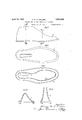
Figs. 7 8, 9, 10 and 11 are detail views of the sleeve.
Fig. .7 being an elevation.
Fig. 8 a plan.
Fig. 9 an inverted plan, and
'Figs. 10 and 11 transverse sections on the lines X, X and XI, XI, respectively.
Figs. 12 to 17 are detail views of the locking and release device.
, Fig. 12 being a front elevation;
Fig. 13 a side elevation partly in section;
Fig. 14 a view similar to Fig. 13 and showing the swivel locking bolt in its out-ward position;
Figs. 15 and 16 plan views with the cam in section showing the mode in which the cam imparts angular movement to the swivel locking bolt; and
Fig. 17 is a detail view of the'swivel locking bolt and handle cam;
Fig. 6A is a fragmentary view similar to quick Fig. 6 and shows a modification of the spring control means and buffer for the movable part 7 of the mold.
Referring to the drawings, 1 denotes the hottable of the apparatus the hollow part 1a of which may be suppliedwith heat in any convenient manner, and which may be of any appropriate length ,toaccommodate one or more molds, and 2 denotes a framework adapted to support the hot table. 3
is the bottom section of the mold adapted to be secured to the hot table by means of bolts 4 and adapted to accommodate the sole plate 5, the bottom section being shown as divided longitudinally into two parts adapted to be.
screwed together by bolts 6 to hold the sole plate rigidly between them. The bolting of the bottom section to the hot plate ensures maintenance of an even temperature. 7 denotes the main body of the mold which in accordance with the principal features of my invention, in lieu of being divided vertically is in one piece hinged about a hinge pin 8 so that it may be conveniently raised and The sleeve illustratedin F igs. 7 I to 10,
e (which is shown in situ in the mold inFigs.
1 and is of rubber compound, and the parts 120 have their faces indented to. form the serrations on the welt a1. y e
In the embodiment shownthereis attached to the front of the mold plate a quick lookin and release device consisting of a T- shaped swivel bolt 14: hinged tov the front of the hot plate or the like and provided with a cam 15?) co-operating with a cam 15a on the mold, this bolt being providedwith a tail portion 14a adapted on the bolt being swung down about its hinge to raise a plunger 17 engaging the under surface of the moldpart 7 and to initiate theopening movement of the mold. W
The ends of the portions 7 and 3 of the mold are slot-ted as at 7a and 3a, and-the swivel locking bolt 14 is arranged so that by pivotal action it can move into and out of the slots, two lugs or hinged-pins 146 are provided on the bolt to form hinge-pins which are pivoted in sleeves Md housed in recesses 141? formed in the top 1 of the hot plate; the bolt has a lever-like extension 14a which, when the bolt is hinged from the position shown in F ig. 13 to that shown in Fig. 14,
control spewing of the rub- Y en ages a plunger 17 raising the latter, and no causing its upper end to engage with the h nge parts 7 of the mold and raise the latter, as shown In Fig. 1 the rest of the opening movement being accomplished by the handle 7 Z) fixed to the part 7, the opening movement being facilitated by the spring device 9, 9b, the action of which will be described later. 0n the bolt 14 is pivotally secured the cam 15?), and to the p'art 7 is fixed a counterpart cam 15a. The part 15?) is provided with a handle 15cand is held in fixed axial position on the bolt 14 by the nut 14f which screws on to the screwed end of the bolt 14 and is fixed in position by a taper screw 14g screwed into a tapped hole in the bolt 14 and expanding the screw-threaded portion so that the nut 14f is held in position. The upper outer surface of the'cam 15b isrecessed and screw-threaded to take a cap 14h, the interior of which is screw-threaded; the joint action of the cap and nut whilst permitting rotation of the cam 15b holds it fixed in axial position on the bolt.
When the parts are in the position shown in Fig. 12 the cams are in alignment and if the handle 150 be returned to the position shown in Fig. 13 the cams engage and produce the pressure necessary to hold the hinged part 7 of the mold in molding position in relation to the fixed part 3. The under surface of the cam 15?) and the upper surface of the cam 1542 are helical surfaces, that of the cam 15?) ending in a shoulder 15d as shown in Figs. 16 and 17, where this cam is shown in traverse section. 7
Assuming the molds to be in the closed position shown in Fig. 13, it will be seen that if the handle 150 be rotated in the position shown in Fig. 15 the edge 15d engages with the end of the slot 7 a in the part 7, and that further movement of the handle 150 into the position shown in Fig. 16 causes the angular withdrawal of the bolt 14; if the movement of the handle 150 to the position shown in Fig. 16 be sufliciently rapid the bolt 14 is ejected from the slot into the position shown in Fig. 14, the lever 14a having engaged the plunger 17 and raised the mold 7 to the position shown.
The part 7 of the mold is subjected by the spring device 9, 9b, to a turning movement in the direction of the arrow WV (Fig. 1), and this assists the opening of the mold, or the spring action may be such as to cause the opening of the mold when the bolt 14 is released, the construction of the spring sleeve is shown in Fig. 6.
9a is a square rod theeyelet part 90 of which is secured by welding or otherwise to, and so as to close the upper end of'the outer tube 9?) which latter is a sliding fit on'the tube 9; the upper end of the interior of the tube 9 is screw-threaded and is provided with a nut or washer 21 having its exterior screwthreaded and its bore of square cross-sect1on,
the nut 21 screws in the tube 9 and fits the rod 941. The lower end of the rod 9a is screw-threaded to take nuts which secure to the end of the rod 9a a washer 23; a spiral spring 20, initially compressed is interposed between the washer23 and the nut 21; the lower end of the tube 9 is provided with a screw-threaded end plug 96 to which is se cured a rotatable eyelet 9d, which eyelet 9d is threaded on one of the stay bars 2a of to gravity is in the direction of the arrow WV, and in the preferred form a buffer spring 25 is provided to elastically arrest the motion of the part 7. This arrangement isishown in Fig. 6A; in this case a heavy compression spring 25 is introduced between the washer 21 or between a washer 27in contact with the washer 21, and the eyelet end 90 of the rod 9a, which spring acts as a buffer to elastically limit the motion of the direction of the arrow W.
The action of the apparatus for molding a rubber sole to a fabric shoe A is as follows A suitable insole is fitted to the upper of the shoe and there is inserted in the shoe a dilatable last 24 having a nozzle 24a by which it can be connected by suitable com pressed air. A suitable quantity of rubber compound to form the sole andheel is roughly plastered in position on the shoe upper,
the sleeve 12 is now applied to the shoe upper; the shoe upper, the dilatablelast, (which is preferably an. inflatable pneumatic last).
therein and the sleeve thereon are inserted in the upper part of the mold; the upper part is then closed down and secured in position by the locking means as shown in Fig. 1; the last is dilated to the desired extent. It will be seen that the bottom and sides of the sole and heel are formed by the lower part 3 of the mold and the sole plate 5, and that the edge al of the welt is formedby the serrated portion 12a of the sleeve, preferably as to imitate the hand stitching of the usual welt; it will also be seen that the under portion of the sleeve 12 being flexible and therefore following the contour of the rounded portion of the shoe upper, gives a clean joint between the welt and the shoe upper, and prevents the spewing of the rubber compound around the'lower portion of the in (J several molds may be manipulated by a sin gle attendant, each mold being held closed for thenecessary period to ensure complete vulcanization of the rubber sole and heel;
. when the vulcanization is completed, the handle 150is rotated as described, whereupon the bolt 14 is'ejected from the slots andthe part 7 released, the opening movement being com :pl'eted, or assisted by the spring device 9, 9?);
the-spring 25 when fitted serving as a buffer. As the mold is opened the wedge 18 operates the plunger and the latter GJGCtS the shoe.
- Where the washer 27,-and pneumatic control cook 26 are fitted, the mold, when the shoe "is inserted inposition, may be closed, or its closing be facilitated by pneumatic pressure. i In co-operation with the hinge 8 there may the provided a wedge or thelike 18 indicated in Figs. 1,3 and 4 which onopeningthe mold is adapted to be pushed forward by'an abutment on the hinge 8 and to engage a plunger 15 located in a recess in the sole plate so that on the mold being opened the wedge 18 or the like is pushed forward and the plunger 15 elevated against the action of a spring (not shown) whereby to raise the heel of theshoe and thus the shoe itself from its .I'declarethat what I claim and desire to secu-re by Letters Patent is v 1. In apparatus for molding'footwear, a heated multiple-part mold, a sleeve having molding parts of flexible material, the sleeve being located in and serving as a detachable lining for one of the mold parts, the interior surface of the sleeve being a counter part of the corresponding external configuration of the upper of the footwear to :be molded, and the external configuration of the sleeve fitting the interior of the mold part in which it is located.
'2. In apparatus for molding footwear, a heated multiple-part mold, the mold being divided horizontally into two parts, the lower part being of. metal and being adapted to shape the under portion and sides of the sole and heel of the footwear, the upper part of the mold being a single part hinged and adapted to receive the upper of the footwear, a detachable sleeve or lining located between the upper and theupper part :of the mold and'an inflatable last in the -upper,'said upper mold part, sleeve and last being adapted to mold the welt, and the moldable portions .of the footwear above the welt. I
3. In apparatus for molding and curing footwear in combination, a heated multiple-- part mold, and a detachable sleeve'adapted to embrace the'upper of the. shoe and havinga flexible part adapted to fit in the angle be.- tween the welt and the rounded portion of the shoe upper, the external surface of the sleeve being adapted to fit the yinnersurface of the upper part of the mold.
- l. Apparatusfor-molding and curing footwear comprising :a mold having top and bottom sections, the top section of the/mold being in one piece hingedly,mounted,1neans for heating the mold, means for locking the mold in closed position, and a sleeve conforming to the upperof thefootwearand serving as a detachable 'lining'for said top section and provided withmolding partsof I flexible material;
5. Apparatus for molding and curing footwear comprising :a hot table and a mold divided horizontally the top section of the mold being. hingedly mounted to the hot table, and a sleeve conforming to the upper of the footwear and serving as a detachable lining for said top section and provided at the dividing line of the mold with flexible molding parts.
6. Apparatus for molding and curing footwear comprising :a hot plate, a mold divided along the welt line of the. shoe, the bottom section of the mold being fixed to the hot plate, and a sleeve conforming to the upper of the footwear and serving as a detach;- able lining for a part of the mold and having a molding part at' the welt line of the shoe.
7. Apparatus constructed in accordance with claim 4;, in which the bottom section is divided longitudinally forthe convenient insertion, removal, interchanging and 'seourin' of the sole plates, bolts securing said mold section parts together, and a hot (plate upon which said mold section is secure 8. The combination with apparatus constructed in accordance with claim 4, of means for ejecting the footwear from the lower part of the mold as the mold is opened, said latter part is openedto be moved so as to raise the said plunger.
10. Apparatus for molding and curing footwear comprising :a multiple-part mold in which the top section of the mold is in one piece hingedly mounted, means for heating the mold, means for locking the mold in closed position, a spring actuated device normally tending to open the mold, and a sleeve conforming to the upper of the footwear and removably arranged in the mold and provided with flexible molding parts.
11. Apparatus for molding and curing footwear comprising :a multiple-part mold in which the top section of the mold is in one piece hingedly mounted, means for heating the mold, means for locking the mold in closed position, and a spring actuated device normally tending to open the mold, said device comprising :an outer tubular portion adapted to be pivotally connected to one of the two parts of the mold between which there is pivotal action in opening; an inner tube sllding therein adapted to be pivotally connected to the other part of the mold, said inner tube having its interior screw-threaded; an adj usting nut fitting the screw-threaded part; a rod connected to the outer tube extending through the tubes and fitting the bore of the said nut so as to be incapable of rotation relatively thereto; an abutment at the end of the rod; and a spring interposed between the said abutment and the said nut; the outer tube, rod and nut being adapted to be rotated together relatively to the inner tube and thereby adjust the initial degree of compression of the spring.
12. The combination with the elements of claim 11, of a spiral buffer spring interposed between the adjusting nut in the inner tube and the pivoted end of the outer tube.
13. The combination with the elements of claim 11, of pneumatic means for closing the mold, comprising, a washer on the upper surface of the adjusting nut, said washer being a fluid-tight sliding fit on the rod and in the bore of the outer tube, and a control cock connecting the closed interior space of the parts and means for locking the mold in closed position, comprising, a bolt pivotally connected to the fixed part and provided with a rotatably mounted cam held against axial movement, and a counter part cam fixed to the movable part of the mold, and adapted to be engaged by the cam on the bolt.
16. Apparatus for molding and curing footwear comprising :a multiple-part mold in which the top section of the mold is in one piece hingedly mounted, means for heating the mold, a sleeve conforming to the upper of the footwear and removably arranged in the mold and provided with flexible molding parts, and means for locking the mold in closed position, means for opening the mold comprising, a plunger mounted in the fixed part of the mold, engaging the movable part of the mold, and adapted when moved axially to open the latter, and a lever fixed to the swivel bolt and adapted when the latter is swivelled out of engagement with the fixed cam to move the said plunger axially to open the mold.
17. Apparatus for molding and curing footwear comprising a mold having a fixed bottom section and a one-piece hinged top section, said top section being provided with a cam, said top section and cam being provided with a slot, a bolt pivoted for movement into and out of said slot, a cam on the bolt engaging said first cam to lock the mold in closed position, said second cam being movable angularly on the bolt out ofcontact with 7 said first cam, a projecting portion on said second cam adapted to engage the edge of said slot and to impart angular movement to the bolt when this cam is moved angularly out of engagement with said first cam, a plunger in the fixed section of the mold and engaging the hinged section and adapted when moved axially to open the latter, a lever fixed to the bolt and adapted when the latter is moved angularly by said cam projection to move the plunger to open the mold, and means for heating the mold.
In testimony whereof I affix my signature.
CHARLES HORACE RUSSELL COLLlNS.
sure, and a buffer spring interposed between the said washer and the closed end of the hollow tube.
15. Apparatus for molding and curing footwear comprising :a multiple-part mold in which the top section of the mold is in one piece hingedly mounted, means for heating the mold, a sleeve conforming to the upper of the footwear and removably arranged in the 15 mold and provided with flexible molding
Applications Claiming Priority (1)
| Application Number | Priority Date | Filing Date | Title |
|---|---|---|---|
| GB1855098X | 1930-02-14 |
Publications (1)
| Publication Number | Publication Date |
|---|---|
| US1855098A true US1855098A (en) | 1932-04-19 |
Family
ID=10892066
Family Applications (1)
| Application Number | Title | Priority Date | Filing Date |
|---|---|---|---|
| US512434A Expired - Lifetime US1855098A (en) | 1930-02-14 | 1931-01-30 | Apparatus for molding and curing footwear |
Country Status (1)
| Country | Link |
|---|---|
| US (1) | US1855098A (en) |
Cited By (11)
| Publication number | Priority date | Publication date | Assignee | Title |
|---|---|---|---|---|
| US2830324A (en) * | 1952-05-13 | 1958-04-15 | Ro Search Inc | Molds for rubber soled footwear |
| US3343223A (en) * | 1965-09-24 | 1967-09-26 | Ludwig Herbert | Apparatus for making shoes by injection molding of an elastomer |
| US3526932A (en) * | 1966-04-28 | 1970-09-08 | Marcel Jezequel | Mold-holder,more particularly for producing injected articles,such as foot-wear articles or other applications,as well as injecting machines provided with this mold-holder or the like |
| EP3248770A1 (en) * | 2016-05-24 | 2017-11-29 | adidas AG | Sole mold for manufacturing a sole |
| EP3488723A1 (en) * | 2017-11-22 | 2019-05-29 | Werkzeugbau Siegfried Hofmann GmbH | Mold for manufacturing a sole |
| US10645992B2 (en) | 2015-02-05 | 2020-05-12 | Adidas Ag | Method for the manufacture of a plastic component, plastic component, and shoe |
| US10723048B2 (en) | 2017-04-05 | 2020-07-28 | Adidas Ag | Method for a post process treatment for manufacturing at least a part of a molded sporting good |
| US10730259B2 (en) | 2016-12-01 | 2020-08-04 | Adidas Ag | Method for the manufacture of a plastic component, plastic component, and shoe |
| US11135797B2 (en) | 2013-02-13 | 2021-10-05 | Adidas Ag | Methods for manufacturing cushioning elements for sports apparel |
| US11407191B2 (en) | 2016-05-24 | 2022-08-09 | Adidas Ag | Method for the manufacture of a shoe sole, shoe sole, and shoe with pre-manufactured TPU article |
| US11938697B2 (en) | 2016-05-24 | 2024-03-26 | Adidas Ag | Method and apparatus for automatically manufacturing shoe soles |
-
1931
- 1931-01-30 US US512434A patent/US1855098A/en not_active Expired - Lifetime
Cited By (25)
| Publication number | Priority date | Publication date | Assignee | Title |
|---|---|---|---|---|
| US2830324A (en) * | 1952-05-13 | 1958-04-15 | Ro Search Inc | Molds for rubber soled footwear |
| US3343223A (en) * | 1965-09-24 | 1967-09-26 | Ludwig Herbert | Apparatus for making shoes by injection molding of an elastomer |
| US3526932A (en) * | 1966-04-28 | 1970-09-08 | Marcel Jezequel | Mold-holder,more particularly for producing injected articles,such as foot-wear articles or other applications,as well as injecting machines provided with this mold-holder or the like |
| US11945184B2 (en) | 2013-02-13 | 2024-04-02 | Adidas Ag | Methods for manufacturing cushioning elements for sports apparel |
| US11135797B2 (en) | 2013-02-13 | 2021-10-05 | Adidas Ag | Methods for manufacturing cushioning elements for sports apparel |
| US10645992B2 (en) | 2015-02-05 | 2020-05-12 | Adidas Ag | Method for the manufacture of a plastic component, plastic component, and shoe |
| US12089698B2 (en) | 2015-02-05 | 2024-09-17 | Adidas Ag | Cushioning element and shoe |
| US11470913B2 (en) | 2015-02-05 | 2022-10-18 | Adidas Ag | Plastic component and shoe |
| US10974476B2 (en) | 2016-05-24 | 2021-04-13 | Adidas Ag | Sole mold for manufacturing a sole |
| US11964445B2 (en) | 2016-05-24 | 2024-04-23 | Adidas Ag | Method for the manufacture of a shoe sole, shoe sole, and shoe with pre-manufactured TPU article |
| US10639861B2 (en) | 2016-05-24 | 2020-05-05 | Adidas Ag | Sole mold for manufacturing a sole |
| EP3546203A1 (en) | 2016-05-24 | 2019-10-02 | adidas AG | Sole mold for manufacturing a sole |
| US11407191B2 (en) | 2016-05-24 | 2022-08-09 | Adidas Ag | Method for the manufacture of a shoe sole, shoe sole, and shoe with pre-manufactured TPU article |
| EP3248770A1 (en) * | 2016-05-24 | 2017-11-29 | adidas AG | Sole mold for manufacturing a sole |
| US11938697B2 (en) | 2016-05-24 | 2024-03-26 | Adidas Ag | Method and apparatus for automatically manufacturing shoe soles |
| US10730259B2 (en) | 2016-12-01 | 2020-08-04 | Adidas Ag | Method for the manufacture of a plastic component, plastic component, and shoe |
| US12172400B2 (en) | 2016-12-01 | 2024-12-24 | Adidas Ag | Method for the manufacture of a plastic component, plastic component, and shoe |
| US12122114B2 (en) | 2016-12-01 | 2024-10-22 | Adidas Ag | Method for the manufacture of a plastic component, plastic component, midsole and shoe |
| US11504928B2 (en) | 2016-12-01 | 2022-11-22 | Adidas Ag | Method for the manufacture of a plastic component, plastic component, midsole and shoe |
| US10723048B2 (en) | 2017-04-05 | 2020-07-28 | Adidas Ag | Method for a post process treatment for manufacturing at least a part of a molded sporting good |
| US11007738B2 (en) | 2017-11-22 | 2021-05-18 | Werkzeugbau Siegfried Hofmann Gmbh | Mold for manufacturing a sole |
| EP3488723A1 (en) * | 2017-11-22 | 2019-05-29 | Werkzeugbau Siegfried Hofmann GmbH | Mold for manufacturing a sole |
| WO2019101375A1 (en) * | 2017-11-22 | 2019-05-31 | Werkzeugbau Siegfried Hofmann Gmbh | Mold for manufacturing a sole |
| EP3628181B1 (en) * | 2017-11-22 | 2021-08-25 | Werkzeugbau Siegfried Hofmann GmbH | Apparatus and method for manufacturing a sole |
| EP3628181A1 (en) * | 2017-11-22 | 2020-04-01 | Werkzeugbau Siegfried Hofmann GmbH | Mold for manufacturing a sole |
Similar Documents
| Publication | Publication Date | Title |
|---|---|---|
| US1855098A (en) | Apparatus for molding and curing footwear | |
| CN106003780B (en) | One kind is for sole and the integrally formed mold of upper of a shoe and its shoes manufacture craft | |
| US1983705A (en) | Tire and tube repair unit | |
| US3677679A (en) | Moulds for forming footwear | |
| US3350748A (en) | Quick change mold assemblies | |
| US2298043A (en) | Molding machine | |
| US2140692A (en) | Method for manufacturing molded rubber articles | |
| CN103171076A (en) | A clamping structure of EVA shaping mold | |
| US2566797A (en) | Repair mold | |
| US3522340A (en) | Injection molding process | |
| DE572155C (en) | Device for molding plastic masses, in particular for molding rubber soles on footwear | |
| US1837356A (en) | Repair vulcanizer | |
| US3241190A (en) | Apparatus for vulcanizing and/or retreading pneumatic tires | |
| US3141195A (en) | Mold assembly for molded shoe bottom | |
| US2266774A (en) | Machine for use in operating upon shoe uppers | |
| US1899754A (en) | Molded pac type boot and process of constructing same | |
| US1770597A (en) | Hollow metal last | |
| US3189943A (en) | Machine for vulcanizing soles onto shoe bottoms | |
| DE929753C (en) | Method and device for manufacturing a rubber boot | |
| US1643712A (en) | Tire mold | |
| US696246A (en) | Last. | |
| CN109159328A (en) | A kind of TPR sole particular manufacturing craft | |
| US1284198A (en) | Shoe-stretcher. | |
| US1567479A (en) | Vulcanizing mold for rubber footwear | |
| US2635265A (en) | Collapsible last |