US1855094A - Frame for articulated oil-electric locomotives - Google Patents
Frame for articulated oil-electric locomotives Download PDFInfo
- Publication number
- US1855094A US1855094A US478966A US47896630A US1855094A US 1855094 A US1855094 A US 1855094A US 478966 A US478966 A US 478966A US 47896630 A US47896630 A US 47896630A US 1855094 A US1855094 A US 1855094A
- Authority
- US
- United States
- Prior art keywords
- frame
- bumper
- oil
- locomotive
- frames
- Prior art date
- Legal status (The legal status is an assumption and is not a legal conclusion. Google has not performed a legal analysis and makes no representation as to the accuracy of the status listed.)
- Expired - Lifetime
Links
- 230000003137 locomotive effect Effects 0.000 title description 15
- 244000035744 Hura crepitans Species 0.000 description 3
- 238000005266 casting Methods 0.000 description 3
- 230000000994 depressogenic effect Effects 0.000 description 3
- 230000004048 modification Effects 0.000 description 3
- 238000012986 modification Methods 0.000 description 3
- 101100504379 Mus musculus Gfral gene Proteins 0.000 description 1
- NJPPVKZQTLUDBO-UHFFFAOYSA-N novaluron Chemical compound C1=C(Cl)C(OC(F)(F)C(OC(F)(F)F)F)=CC=C1NC(=O)NC(=O)C1=C(F)C=CC=C1F NJPPVKZQTLUDBO-UHFFFAOYSA-N 0.000 description 1
- 230000000284 resting effect Effects 0.000 description 1
- 239000000725 suspension Substances 0.000 description 1
Images

Classifications
-
- B—PERFORMING OPERATIONS; TRANSPORTING
- B61—RAILWAYS
- B61F—RAIL VEHICLE SUSPENSIONS, e.g. UNDERFRAMES, BOGIES OR ARRANGEMENTS OF WHEEL AXLES; RAIL VEHICLES FOR USE ON TRACKS OF DIFFERENT WIDTH; PREVENTING DERAILING OF RAIL VEHICLES; WHEEL GUARDS, OBSTRUCTION REMOVERS OR THE LIKE FOR RAIL VEHICLES
- B61F1/00—Underframes
- B61F1/06—Underframes specially adapted for locomotives or motor-driven railcars
Definitions
- a further object of the invention is to make each frame in a single casting, in which the inner bumpers are extended and in contact one with the other, so as to 'relieve the center bearings of the frame from strain.
- a still further object of the invention is to so design the one-piece frame that a brake cylinder may be cast integral therewith.
- Another object of the invention is to so design certain elements, which heretofore have been made separate, that they are cast integral with the frame.
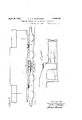
- Fig. 1 is a diagrammatic side view of an articulated oil-electric locomotive made in accordance with my invention
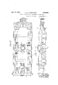
- Fig. 2 is a plan View of the improved integral frame of the locomotive
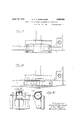
- Fig. 3 is a side view
- Fig. 4 is a sectional view on the line 44, Fig. 3;
- Fig. 5 is a sectional view on the line 55, 5 Fig. 3;
- Fig. 6 is a modification showing the de pressed inner bumper
- Fig. 7 is a view showing the application of twin springs to the frame
- Fig. 8 is a view showing the application of a single spring mounted on the boxes and located on the inside of a box-type frame;
- Figs. 9 and 10 are views of modifications of the invention.
- the body 1 of the locomotive is mounted on two frames 2- 2, each frame being in the form of a truck, and the body of the locomotive rests on the center bearings 3 of the frames 2.
- Each frame has an outer bumper 4 at one end, having pockets 5 for the draftgear and attachments. Formed in the bumper are pollingpockets 6, and directly back of the bumper is the fulcrum 25 for the cross-.
- Sand-boxes 7 are cast in- 'tegral with the frame, directly back of the head 9, and in back of the bumper'8'are sandboxes 10 cast integral with the frame.
- each draw-head 9' is curved as at 11,
- FIG. 13 is a cross-tie forming an integral part of the frame, and this cross-tie has a centerbearing 14, on which rests the body of the locomotive.
- Formed integral with the. crosstie are the fulcrumbrackets 15 for the brake mechanism and the suspension lugs 16 for A the electric motors.
- Projecting upwardly' from the frame are the side-bearings 17-.
- the brake-cylinders 22 in the present instance are bolted on the frame, being partially enclosed within a pocket 18.
- Theside-frames-l-Q-IQ which connect the i outer bumper, cross-tie and inner bumper,
- the springs .a'a shown in Fig. 7 are twin springs, one'being on the outside of the, frame and the other being on the inside of the frame. These springs are similar to those shown in the patent granted to John S. Keen, No. 1,530,373, v
- Fig. 8 the frame is made to accommodate single driving springs 6, each spring being encased in a hollow frame and resting upon the boxes between the pedestal s.
- Fig. 1 is shown the electric cells 21 suspended from the underside of the body of the locomotive at the center thereof, and in this instance. theinner end ofieachframe is depressed as shown in Figs. 1 and 6, so as to clear these cells.
- the storage batteries are used to. energize the generatorg'which is used as 'a'motor to start the oil' engine on the locomotive, and the storage battery isused also for lighting and for control circuits.
- Figs. 9 and 10 illustrate a modification in v a frame.
- each frame having a centrally located center bearing cross-tie; a body portion mounted above the two frames and havingtwo center bearings mo-untedon the center bearings of c I the cross-ties of the frames, each frame having a bumper at each end, the outer bumpers extending beyond the body of the locomotive, the inner bumpers being in contact with each other, soas to have a rubbing action; and
- each frame having acenter bearing cross-tie; a body portlon mounted above the 7 two frames and having center bearings 5.
- A'frame for an oil-electric locomotive mounted on the center bearings of the crossties of the frames, each frame being made as y i an integral structure and having a bumper at each end, the inner bumpers being curved so the bumper of one frame will rub against the bumper of the other frame, each frame having'i'nte gral side bearings, brake cylinder supports, and havmg at one end a fulcrum for a cross-equal1z1ng beam.
Landscapes
- Engineering & Computer Science (AREA)
- Mechanical Engineering (AREA)
- Arrangement Or Mounting Of Propulsion Units For Vehicles (AREA)
Description
April 1 1932- c c c. BURKHARDT FRAME FOR ARTICULATED OIL ELECTRIC LOCOMOTIVES Filed Aug. 30, 1930 4 Sheets-Sheet April 19, 1932. c. c. c. BURKHAR DT .FRAME F'OR ARTICULATED OIL ELECTRIC LOCOMOTIVES Filed Aug. 30, 1930 4 Sheets-sheet rlllllllll April 19; 1932. c. c. c BURKHARDT 1,355,094
FRAME FOR ARTICULATED OIL ELECTRIC LOCOMOTIVES Filed Aug. 30, 1930 4 Sheets-Sheet 3 $47 Maw A ril 19, 1932 c C BURKHARDT 1,855,094
FRAME FOR ARTICULA'TED on, ELECTRIC LOCOMOTIVES Filed Aug. 30. 1930 4 Sheets-Sheet III/llllflflllllIlI d I I a Patented Apr. 19, 1932 UNITED STATES PATENT OFFICE CONRAD C. G. IBURKHARDT, OF IPIIILADELPHIA, PENNSYLVANIA FRAME FOR ARTICULATED OIL-ELECTRIC LOCOMOTIVES Application filed August 30, 1930. Serial No. 473,966.
A further object of the invention is to make each frame in a single casting, in which the inner bumpers are extended and in contact one with the other, so as to 'relieve the center bearings of the frame from strain.
A still further object of the invention is to so design the one-piece frame that a brake cylinder may be cast integral therewith.
Another object of the invention is to so design certain elements, which heretofore have been made separate, that they are cast integral with the frame.
In the accompanying drawings:
Fig. 1 is a diagrammatic side view of an articulated oil-electric locomotive made in accordance with my invention;
Fig. 2 is a plan View of the improved integral frame of the locomotive;
Fig. 3 is a side view;
Fig. 4 is a sectional view on the line 44, Fig. 3;
Fig. 5 is a sectional view on the line 55, 5 Fig. 3;
Fig. 6 is a modification showing the de pressed inner bumper;
Fig. 7 is a view showing the application of twin springs to the frame;
Fig. 8 is a view showing the application of a single spring mounted on the boxes and located on the inside of a box-type frame; and
Figs. 9 and 10 are views of modifications of the invention.
The body 1 of the locomotive is mounted on two frames 2- 2, each frame being in the form of a truck, and the body of the locomotive rests on the center bearings 3 of the frames 2. Each frame has an outer bumper 4 at one end, having pockets 5 for the draftgear and attachments. Formed in the bumper are pollingpockets 6, and directly back of the bumper is the fulcrum 25 for the cross-.
equalizing beam. Sand-boxes 7 are cast in- 'tegral with the frame, directly back of the head 9, and in back of the bumper'8'are sandboxes 10 cast integral with the frame. The
outer bumper. At the opposite end of the frame is the inner bumper 8, having adrawface of each draw-head 9'is curved as at 11,
and the draw-head of one frame abuts that of the adjoining frame, and the two frames are connected by a link 12' shown by dotted lines.
13 is a cross-tie forming an integral part of the frame, and this cross-tie has a centerbearing 14, on which rests the body of the locomotive. Formed integral with the. crosstie are the fulcrumbrackets 15 for the brake mechanism and the suspension lugs 16 for A the electric motors. Projecting upwardly' from the frame are the side-bearings 17-. The brake-cylinders 22 in the present instance are bolted on the frame, being partially enclosed within a pocket 18.
Theside-frames-l-Q-IQ, which connect the i outer bumper, cross-tie and inner bumper,
are provided with pedestals 20, and. on the frame are located points of attachment for the driving spring links- The springs .a'a shown in Fig. 7 are twin springs, one'being on the outside of the, frame and the other being on the inside of the frame. These springs are similar to those shown in the patent granted to John S. Keen, No. 1,530,373, v
datedMarch 17, 1925. In Fig. 8 the frame is made to accommodate single driving springs 6, each spring being encased in a hollow frame and resting upon the boxes between the pedestal s.
In Fig. 1 is shown the electric cells 21 suspended from the underside of the body of the locomotive at the center thereof, and in this instance. theinner end ofieachframe is depressed as shown in Figs. 1 and 6, so as to clear these cells. The storage batteries are used to. energize the generatorg'which is used as 'a'motor to start the oil' engine on the locomotive, and the storage battery isused also for lighting and for control circuits.
Figs. 9 and 10 illustrate a modification in v a frame.
which the brake cylinders 22a are cast integral with the frame. Within the cylinders are bushings 23. In this instance the brake dead lever fulcrum 24 is an integral part of the cylinder head.
I claim: s
1. The combination in an oil-electric articulated flocomotive, of a body portion; two frames on which the body portion is pivotal lymounted, each frame being made as an integral casting, one frame being coupled to the other and each frame having an outer and an inner draw-head, the inner draw-head and a portion of the frame being depressed; and
storage batteries suspended from'the body of the locomotive and occupying the space directly above the depressed portions of the 2. The combination in an oil-electric articulated locomotive, oftwo frames connected together; axle box pedestals on the frames,
' each frame having a centrally located center bearing cross-tie; a body portion mounted above the two frames and havingtwo center bearings mo-untedon the center bearings of c I the cross-ties of the frames, each frame having a bumper at each end, the outer bumpers extending beyond the body of the locomotive, the inner bumpers being in contact with each other, soas to have a rubbing action; and
means connecting the inner endsof the two frames.
3. The combination in an oil-electric articulated locomotive, of two frames coupled together; a body portion having a center bearing mounted on each frame, each frame being .made as an integral casting and having a bumper at each end; a center bearing crosstie; and sand boxes at the four corners of the frame at theijunction of the side members with thebumpers. 1
gether, each frame having acenter bearing cross-tie; a body portlon mounted above the 7 two frames and having center bearings 5. A'frame for an oil-electric locomotive mounted on the center bearings of the crossties of the frames, each frame being made as y i an integral structure and having a bumper at each end, the inner bumpers being curved so the bumper of one frame will rub against the bumper of the other frame, each frame having'i'nte gral side bearings, brake cylinder supports, and havmg at one end a fulcrum for a cross-equal1z1ng beam.
made in a singlecasting and consisting of longitudinal sideframes; an outer bumper and an inner bumper; a center bearing crosstie on which the body of the locomotive is pivotally mounted; and a. fulcrum for a crossequalizing beam locateddirectlyback of the outer bumper.
ooivnn no'. CLBURKHARDT; (r
r V 4. The combination'in an oil-electric articulated'locomotive, of two frames coupled to-
Priority Applications (1)
| Application Number | Priority Date | Filing Date | Title |
|---|---|---|---|
| US478966A US1855094A (en) | 1930-08-30 | 1930-08-30 | Frame for articulated oil-electric locomotives |
Applications Claiming Priority (1)
| Application Number | Priority Date | Filing Date | Title |
|---|---|---|---|
| US478966A US1855094A (en) | 1930-08-30 | 1930-08-30 | Frame for articulated oil-electric locomotives |
Publications (1)
| Publication Number | Publication Date |
|---|---|
| US1855094A true US1855094A (en) | 1932-04-19 |
Family
ID=23902121
Family Applications (1)
| Application Number | Title | Priority Date | Filing Date |
|---|---|---|---|
| US478966A Expired - Lifetime US1855094A (en) | 1930-08-30 | 1930-08-30 | Frame for articulated oil-electric locomotives |
Country Status (1)
| Country | Link |
|---|---|
| US (1) | US1855094A (en) |
-
1930
- 1930-08-30 US US478966A patent/US1855094A/en not_active Expired - Lifetime
Similar Documents
| Publication | Publication Date | Title |
|---|---|---|
| US4628824A (en) | Self steering railway truck | |
| US2098459A (en) | Car truck | |
| US2241757A (en) | Vehicle | |
| US1855094A (en) | Frame for articulated oil-electric locomotives | |
| GB1245645A (en) | Improvements in or relating to railway trains | |
| US3288083A (en) | Locomotive truck | |
| US2925789A (en) | Railway vehicle structure | |
| US2191408A (en) | Engine truck stabilizer | |
| US1275612A (en) | Locomotive-engine. | |
| US2253407A (en) | Railway truck | |
| US1510539A (en) | Locomotive truck | |
| US1769359A (en) | Flexible convertible railroad-car truck | |
| US2257909A (en) | Draft arrangement | |
| US1704652A (en) | Crosstie for electric locomotives | |
| US2138139A (en) | Locomotive underframe buffer | |
| US2259477A (en) | Railway truck | |
| US1833094A (en) | Locomotive frame | |
| US1547667A (en) | Locomotive driving box | |
| US1729434A (en) | Engine truck | |
| US1780082A (en) | Two-wheel locomotive truck | |
| US1810876A (en) | Railway car | |
| US2703056A (en) | Railway truck | |
| US1704272A (en) | Locomotive-frame structure | |
| US1801938A (en) | Oil-electric-locomotive platform | |
| US3037466A (en) | Railway vehicle structure |