US185508A - Improvement in gas apparatus - Google Patents
Improvement in gas apparatus Download PDFInfo
- Publication number
- US185508A US185508A US185508DA US185508A US 185508 A US185508 A US 185508A US 185508D A US185508D A US 185508DA US 185508 A US185508 A US 185508A
- Authority
- US
- United States
- Prior art keywords
- retorts
- members
- oven
- gas
- oil
- Prior art date
- Legal status (The legal status is an assumption and is not a legal conclusion. Google has not performed a legal analysis and makes no representation as to the accuracy of the status listed.)
- Expired - Lifetime
Links
Images

Classifications
-
- A—HUMAN NECESSITIES
- A63—SPORTS; GAMES; AMUSEMENTS
- A63B—APPARATUS FOR PHYSICAL TRAINING, GYMNASTICS, SWIMMING, CLIMBING, OR FENCING; BALL GAMES; TRAINING EQUIPMENT
- A63B9/00—Climbing poles, frames, or stages
Definitions
- the object of this invention is to improve still further the construction of simple, cheap, and efficient apparatus for the manufacture of illuminating-gas of hydrogen and the vapor of hydrocarbon substances, such as that for which a patent was granted to me the 16th day of November, 1875, consisting of a furnace and oven, in which are two series or benches of retorts, (one for the oil and another for steam,) contrived in a simple way for graduating the heat according to the progress of the work.
- the retorts which are of cast-iron, comprising four parallel members, are arranged with the said members all in the horizontal plane, whereby a given capacity is obtained with less height than when the coils are so made that some of the members are in a higher plane than the others, as in the aforesaid patent, thus enabling the apparatus to be constructed lower and more compact, and the several members of the retorts are united along their whole length by connectin g-plates cast together with them for the purpose of greater strength and durability and in connection with the retorts so arranged I have contrived a series of passages from the furnace into thelower oven containing the retorts, along each sideof the furnace, and in addition to the usual passage at the rear, whereby the heat impinges uniformly against the several members of theretorts, and attacks the substances to be treated, when they leave the oven, with far greater effect than when it all enters at the rear end, and passes along the retort
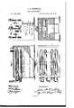
- Figure 1 is a longitudinal sectional elevation of my improved apparatus.
- Fig. 2 is a horizontal section.
- Fig. 3 is an end elevation, and
- Fig. 4. is a transverse section.
- A represents one series of retorts, say for the steam and B, the other series for the hydrocarbon substance. They are arranged one above another, in two benches, in the oven G, which is separated from the furnace P by the horizontal partition 8, and is divided by another partition, D.
- Each retort is composed of four parallel members, I), connected by three bends, a, and by the plates d, and all being in the same horizontal plane, as aforesaid, for reducing the height of the apparatus as much as possible; and along each side of the furnace is a series of side passages, f, in addition to the rear passage R, from the fire-space around the partition 6 and into the oven G, so arranged as todischarge the heat passing through them against each member of the retorts at the front, as before described.
- Each set of re- I torts has a feeding-pipe, E, with a stopcock, L, and they connect at I with the pipe H, for conducting the gas to thehydraulic main.
- J represents escape-pipes discharging into the oven, and having stopcocks K, to be opened when the making of gas is to be stopped, for allowing the matters remaining in the retorts to escape into the fire and be consumed, or pass off through the chimney to prevent any offensive smell from the apparatus.
- M represents the exterior pipes connecting the difierent retorts of each bench.
- the operation of the device is about as follows: The fire is started in the generator, and
- the water on the other side is first converted into steam, and this, as it progresses along the surfaceof the incandescent retorts, is partially decomposed, and the resulting hydrogenis inti- *mately mingled with the gases produced in the other bench from the superbeatingof the oil, thus materially increasing the volume of the1gas, and reducing its excessive richness and liability to subsequent condensation.
Landscapes
- Health & Medical Sciences (AREA)
- General Health & Medical Sciences (AREA)
- Physical Education & Sports Medicine (AREA)
- Production Of Liquid Hydrocarbon Mixture For Refining Petroleum (AREA)
Description
J. H. EICHHOLZ.
GAS APPARATUS.
No. 185,508. Patented Dec. 19, 1876.
UNITED STATES PATENT OEEIoE JOHN H. EIOHHOLZ, OF BROOKLYN, NEW YORK.
IMPROVEMENT IN GAS APPARATUS.
Specification forming part of Letters Patent No. 185,508, dated December 19, 1876 application filed September 22, 1876.
To all whom tt may concern:
Be it known that I, JOHN H. EIoEHoLz, of Brooklyn, in the county of Kings and State of New York, have invented a new and useful Improvement in Gas Apparatus, of which the following is a specification:
The object of this invention is to improve still further the construction of simple, cheap, and efficient apparatus for the manufacture of illuminating-gas of hydrogen and the vapor of hydrocarbon substances, such as that for which a patent was granted to me the 16th day of November, 1875, consisting of a furnace and oven, in which are two series or benches of retorts, (one for the oil and another for steam,) contrived in a simple way for graduating the heat according to the progress of the work.
In the present invention the retorts, which are of cast-iron, comprising four parallel members, are arranged with the said members all in the horizontal plane, whereby a given capacity is obtained with less height than when the coils are so made that some of the members are in a higher plane than the others, as in the aforesaid patent, thus enabling the apparatus to be constructed lower and more compact, and the several members of the retorts are united along their whole length by connectin g-plates cast together with them for the purpose of greater strength and durability and in connection with the retorts so arranged I have contrived a series of passages from the furnace into thelower oven containing the retorts, along each sideof the furnace, and in addition to the usual passage at the rear, whereby the heat impinges uniformly against the several members of theretorts, and attacks the substances to be treated, when they leave the oven, with far greater effect than when it all enters at the rear end, and passes along the retorts lengthwise to the point where the substances enter, and this, too, with less width of oven than the other arrangement demands, because the retorts may be placed close along the oven-wall, and will receive the heat more directly and equally from the passages. Thus the furnace may be made narrower for a given capacity.
Figure 1 is a longitudinal sectional elevation of my improved apparatus. Fig. 2 is a horizontal section. Fig. 3 is an end elevation, and Fig. 4. is a transverse section.
Similar letters of reference indicate corresponding parts.
A represents one series of retorts, say for the steam and B, the other series for the hydrocarbon substance. They are arranged one above another, in two benches, in the oven G, which is separated from the furnace P by the horizontal partition 8, and is divided by another partition, D. Each retort is composed of four parallel members, I), connected by three bends, a, and by the plates d, and all being in the same horizontal plane, as aforesaid, for reducing the height of the apparatus as much as possible; and along each side of the furnace is a series of side passages, f, in addition to the rear passage R, from the fire-space around the partition 6 and into the oven G, so arranged as todischarge the heat passing through them against each member of the retorts at the front, as before described. Each set of re- I torts has a feeding-pipe, E, with a stopcock, L, and they connect at I with the pipe H, for conducting the gas to thehydraulic main. J represents escape-pipes discharging into the oven, and having stopcocks K, to be opened when the making of gas is to be stopped, for allowing the matters remaining in the retorts to escape into the fire and be consumed, or pass off through the chimney to prevent any offensive smell from the apparatus. M represents the exterior pipes connecting the difierent retorts of each bench.
By the arrangement it will be perceived the lowest members of both benches of retorts receive the highest degree of heat. Those above receive somewhat less, and the uppermost receive the least, and the materials employed in the process, which are fed through trapped pipes into the uppermost retorts of each series, are therefore subjected, in their passage downward through the several connected members of the system, to a graduallyincreasing heat, which reaches its maximum in the lowest members of each, at the respective outlets of which the highly-heated contents of both series unite.
The operation of the device is about as follows: The fire is started in the generator, and
whenthe upper'retorts are heated to a cherryred a fine stream of crude petroleum is allowed to enter one of the retort series, say the right-hand bench, through the inlet-"pipebe-- fore described, while simultaneously a fine stream of wateruis allowed to enter the lefthand bench. The petroleum, on reaching the heated surface of the first retort, is instantly vaporized, and the vapors, progressing successively into the lower and hotter members of the series, are largely converted into permanent gas, while a certain proportion of carbon is deposited on the inside of the retorts. The water on the other side is first converted into steam, and this, as it progresses along the surfaceof the incandescent retorts, is partially decomposed, and the resulting hydrogenis inti- *mately mingled with the gases produced in the other bench from the superbeatingof the oil, thus materially increasing the volume of the1gas, and reducing its excessive richness and liability to subsequent condensation.
When the operation is to be repeated the oil is to be admitted from the other side of the retort system, where the water was previously admitted, and the latter is fed into what was previously the oil side. Just here an ingenious compensating operation comes into play, for the steam coming into contact with the thin layer of incandescent carbon deposited from the oil in the previous operation is decomposed by it, the resultant being watergas (hydrogen and carbonic oxide) and some *carbonic acid,bythe addition of which the volume of the resulting illuminating-gas is materially increased, and its density and liability to condense r d'uhed, asf'p sonny-assessed,
while 'thecarbondeposit isthoroughly removed from the retorts. "In the next operation the places of admission of water and oil are again reversed with the same result.
Thisprocess of alternating the places of admission of water and oil into the two benches should, theoretically,take place at every fresh make of gasybut, in practice, it has been found I to be not absolutely necessary. If this is not done, however, with a certain regularity, the a retorts through whichqthee steampasses will i I certainly sufl'er a rapidoxidation. The regular alternation of the places of admission of wa- 1 1.
ter and oil is, therefore, anecessary condition of the successful workingc ofthesystem.
These retorts are applicableto the ordinary y r fire-brick furnacesof large gas-works,;as well a a as the portable apparatusl here shown.
Having thus described my-invention,1I
claim as new and desire to secure by Letters Patent- The combination, with; the, furnace P and oven G, having the: lateral side passagesf, rear passages R, and the partitions e I), of the steam-retorts A and oil retorts B, constructed in several parallel members, b, which are arranged in one and the .samehorizontal plane, and connected by theqplates d, the whole bei ing cast in one piece, substantially as speci- WM. J. MORGAN, F. A. THAYER.
Applications Claiming Priority (1)
| Application Number | Priority Date | Filing Date | Title |
|---|---|---|---|
| US185508TA | 1876-09-22 | 1876-09-22 |
Publications (1)
| Publication Number | Publication Date |
|---|---|
| US185508A true US185508A (en) | 1876-12-19 |
Family
ID=2254914
Family Applications (1)
| Application Number | Title | Priority Date | Filing Date |
|---|---|---|---|
| US185508D Expired - Lifetime US185508A (en) | 1876-09-22 | 1876-09-22 | Improvement in gas apparatus |
Country Status (1)
| Country | Link |
|---|---|
| US (1) | US185508A (en) |
-
1876
- 1876-09-22 US US185508D patent/US185508A/en not_active Expired - Lifetime
Similar Documents
| Publication | Publication Date | Title |
|---|---|---|
| US185508A (en) | Improvement in gas apparatus | |
| US338992A (en) | Process of and apparatus for manufacturing gas | |
| US360945A (en) | John d | |
| US292944A (en) | Signoes | |
| US363945A (en) | Beinhold boeklen | |
| US1975396A (en) | Coal carbonizing apparatus | |
| US216119A (en) | Improvement in gas-generators | |
| US132265A (en) | Improvement in the manufacture of illuminating gas from hydrocarbons | |
| US270427A (en) | Apparatus for making gas | |
| US326959A (en) | Apparatus for making gas | |
| US53359A (en) | Improvement in distilling apparatus | |
| US151283A (en) | Improvement in the processes and apparatus for making water-gas | |
| US176610A (en) | Improvement in processes of manufacturing illuminating-gas | |
| US767217A (en) | Gas-generator. | |
| US956019A (en) | Manufacture of gas. | |
| US392458A (en) | Manufacture of gas | |
| US595857A (en) | miller | |
| US198340A (en) | Improvement in apparatus for generating illuminating-gas | |
| US352620A (en) | Thirds to alexander ross | |
| US766554A (en) | Process of manufacturing gas. | |
| US470040A (en) | Apparatus for the manufacture of gas | |
| US145021A (en) | Improvement in the manufacture of gas | |
| US722982A (en) | Coking-oven. | |
| US547786A (en) | herring | |
| US151002A (en) | Improvement in the manufacture of gas for heating and illuminating |