US1855086A - Multiple electric fuse - Google Patents
Multiple electric fuse Download PDFInfo
- Publication number
- US1855086A US1855086A US503595A US50359530A US1855086A US 1855086 A US1855086 A US 1855086A US 503595 A US503595 A US 503595A US 50359530 A US50359530 A US 50359530A US 1855086 A US1855086 A US 1855086A
- Authority
- US
- United States
- Prior art keywords
- fuse
- shell
- arm
- contact
- ring
- Prior art date
- Legal status (The legal status is an assumption and is not a legal conclusion. Google has not performed a legal analysis and makes no representation as to the accuracy of the status listed.)
- Expired - Lifetime
Links
- 238000010276 construction Methods 0.000 description 8
- 238000004519 manufacturing process Methods 0.000 description 2
- 230000004048 modification Effects 0.000 description 2
- 238000012986 modification Methods 0.000 description 2
- 101100203596 Caenorhabditis elegans sol-1 gene Proteins 0.000 description 1
- 230000000694 effects Effects 0.000 description 1
- 239000011810 insulating material Substances 0.000 description 1
- 229910052573 porcelain Inorganic materials 0.000 description 1
Images
Classifications
-
- H—ELECTRICITY
- H01—ELECTRIC ELEMENTS
- H01H—ELECTRIC SWITCHES; RELAYS; SELECTORS; EMERGENCY PROTECTIVE DEVICES
- H01H85/00—Protective devices in which the current flows through a part of fusible material and this current is interrupted by displacement of the fusible material when this current becomes excessive
- H01H85/02—Details
- H01H85/26—Magazine arrangements
Definitions
- the salient object of this invention is to provide an improved electric fuse construction of the character described herein embodyin apluralityof fusible strips.
- Anot or object of the invention is to provide an improved multiple fuse construction of the character described herein which will be convenient in use and which will eliminate the trouble of testing for a burnt fuse;
- the invention embodying a rotatable member adapted to make contact selectivelywith one of a plurality of fuse strips so that the fuse plug need not. be removed until all of the use strips have been burnt out.
- Fig. 1 is a side elevational view of a preferred form of construction of the inven-' tion
- Fig. 2 is a top plan view taken'substantially on the line 2-2 in Fig. 1;
- - Fig. 3 is a sectional detail view stantially on the line 3-3 in Fig. 2;
- Fi 4 is a sectional detail view taken substantially on the line 4-4 in Fig. 3;
- FIG. 10 is a porcelain or the like insulating body on which is provided an annular shoulder 11
- a corrugated band 12 is disposed about the body 10 so that the fuse plug may be inserted into the usual electric socket, and this band 12 taken 1 sub includes an inwardly extending flange 13 which is disposed below the shoulder 11;
- the body 10 inclu es the annular head portion 16 in which are provided radially extending grooves 17 which are continuous with the grooves 15 and each of these grooves 17 has continuous therewith a recess 17 which ex-' tends parallel to the grooves 15.
- a plurality of fusible strips 18 are provided and each of these strips includes a main body portion 19 which extends through one of the grooves 15, a, portion 20 which extends through corresponding grpoves 17, and a portion 21 which is disposed in the corresponding recess 17'.
- the lower ends of the strips 18 are bent, as at 22, below the shoulder 11 and these end portions 22 are soldered to the band 12 as at 23, it being apparent that these lower end portions 22 extend through 0 enings 24 in the side wall of the insulating ody 10 below the shoulder 11.
- a pin 27 integral with the lower end of which is the contact member 28.
- a constricted portion 29 is provided upon this portion 29 is a conductive arm 30,
- a contact element 31 which is adapted for selective contact with the portions 20 of the fuse strips 18.
- w Extending circumferentially around the outer periphery of the head portion 16 of the insulating body '10 is an annular groove 32.
- a ring 35 the outer side of which is referably knurled to facilitate movement t ere-ff of by the fingers.
- the ring 35 includes a flange 36 which overhangs the outer end of Q the head portion '16, and the arm 30 is sol- 1 i dered to this flange 36 as at 38.
- a sto 37 I is provided on the upper or outer end 0 the head portion 16 of t e body 10;
- a multiple electric fuse comprising a shell of insulating material, a conductive band disposed on the exterior of said shell, fusible members radially arranged about the inner periphery of said shell, a pin extending through said shell and having a contact portion at one end thereof, a conductive contact arm having its inner end rotatably mounted on said pin, a ring rotatableiabout said shell and having the outer end of said arm secured thereto, whereby said ring may be rotated to selectively contact said arm with the outer end of any one of said fusible members, said fusible members having the inner ends thereof connected to said band.
- a multiple electric fuse plug comprising an insulating shell having rooves at radial intervals on the inner perip ery there of, fusible members in said grooves, a con-' ductive' band about said shell having the inner ends of said fusible members connected thereto, a pin extended through said shell, and including a contact portion at one end thereof, a conductive arm having one end rotatably mounted on the other end of said pin, a ring rotatably mounted on said shell and havin the other end of said arm secured I thereto, w ereby said ring may be rotated to selectively contact said arm with any one of said fusible members.
- a multiple electric fuse plug comprising an insulating shell including an annular head portion having slots formed at radial intervals therein said shell having a plurality of arallei rooves on the inner periphery tereof, usible members in said grooves with portions in said slots, 9. conductive band about said shell having the inner ends of'said fusible members connected thereto, a pin extended through said shell and having a contact at the inner end thereof,
- a ring rotatably mounted on said head portion and having the outer end of said arm secured thereto, and a contact member on said arm, whereby said ring may be rotated to selectively contact said contact member with any one of said portions of said fusible members, said head portion having an annular grove therein, and guiding means carried by said ring and movable in said annular groove.
- a multiple-electric fuse plug comprising an insulating shell including an annular head portion having slots formed at radial intervals therein, said shell having a plurality of parallel grooves on the inner periphery thereof, fusible members in said grooves with portions in said slots, a conductive band about said shell having the inner ends of said fusible members connected thereto, a pinextended through said shell and having a contact at the inner end thereof, an arm having its inner end rotatably mounted on the outer end of said pin, a rin rotatably mounted on said head portion an having the outer end of said arm secured thereto, a contact member on said arm, whereby said ring may be rotated to selectively contact said contact member with any one of ,said portions of said fusible members, said head portion having an annular groove therein, guiding means carried by said ring and movable in said annular groove, and a stop member in said head portion engageable by said arm for preventing movement of said ring after all of said fusible members have been fused
Landscapes
- Fuses (AREA)
Description
April 19, 1932. e. 1.. BLADHOLM MULTIPLE ELECTRIC FUSE Filed Dec. 19, 1930 alim- L I NVINTOI HIS ATTORNEY UNITED- STATES cannon n nnannonu, or cnrcaco, rumors I Patented Apr. 19, 1932 KULTIPLE ELECTRIC FUSE Application Med December 19, 1930. Serial No. 503,595.
-This invention relates to certain novel improvements in multiple electric fuses, and
as for its principal object the provision of an improved construction of this character I which will be highly eflicient in use and economical in manufacture.
' The salient object of this invention is to provide an improved electric fuse construction of the character described herein embodyin apluralityof fusible strips.
Anot or object of the invention is to provide an improved multiple fuse construction of the character described herein which will be convenient in use and which will eliminate the trouble of testing for a burnt fuse;
the invention embodying a rotatable member adapted to make contact selectivelywith one of a plurality of fuse strips so that the fuse plug need not. be removed until all of the use strips have been burnt out.
Other objects will appear hereinafter.
The invention consists in the novel combination and arrangement of parts to be hereinafter described and claimed. v
The invention will be best understood by reference to the accompanying drawings,
showing the preferred form of construction and in which: v
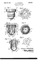
Fig. 1 is a side elevational view of a preferred form of construction of the inven-' tion; I
Fig. 2 is a top plan view taken'substantially on the line 2-2 in Fig. 1;
- Fig. 3 is a sectional detail view stantially on the line 3-3 in Fig. 2;
Fi 4 is a sectional detail view taken substantially on the line 4-4 in Fig. 3;
ferred form of construction of the invention is depicted, generically indicated at 10 is a porcelain or the like insulating body on which is provided an annular shoulder 11 A corrugated band 12 is disposed about the body 10 so that the fuse plug may be inserted into the usual electric socket, and this band 12 taken 1 sub includes an inwardly extending flange 13 which is disposed below the shoulder 11;
' Provided on the inner wall 14 of the body 10 is a pluralit of parallel grooves 15. The body 10 inclu es the annular head portion 16 in which are provided radially extending grooves 17 which are continuous with the grooves 15 and each of these grooves 17 has continuous therewith a recess 17 which ex-' tends parallel to the grooves 15.
A plurality of fusible strips 18 are provided and each of these strips includes a main body portion 19 which extends through one of the grooves 15, a, portion 20 which extends through corresponding grpoves 17, and a portion 21 which is disposed in the corresponding recess 17'. The lower ends of the strips 18 are bent, as at 22, below the shoulder 11 and these end portions 22 are soldered to the band 12 as at 23, it being apparent that these lower end portions 22 extend through 0 enings 24 in the side wall of the insulating ody 10 below the shoulder 11.
26 is provided, and extended throu h this opening and through the center of t efuse plug is a pin 27 integral with the lower end of which is the contact member 28. At. the upper end of the in 27 a constricted portion 29 is provided upon this portion 29 is a conductive arm 30,
in the outer end of which is mounted a contact element 31 which is adapted for selective contact with the portions 20 of the fuse strips 18. w Extending circumferentially around the outer periphery of the head portion 16 of the insulating body '10 is an annular groove 32.
Slidably mounted on the head portion 16 bg means of guiding elements 33 and 34 whic and revolvablymounted .2
include portions that travel in the groove 32': is a ring 35, the outer side of which is referably knurled to facilitate movement t ere-ff of by the fingers. The ring 35 includes a flange 36 which overhangs the outer end of Q the head portion '16, and the arm 30 is sol- 1 i dered to this flange 36 as at 38. A sto 37 I is provided on the upper or outer end 0 the head portion 16 of t e body 10;
, The operation of the fuse is as follows:
When the fuse plug is screwed into the standard base or soc et current will flow through the corrugated band 12, fuse strip portion 22, the body 19 of one of the fuses 18, portion 20 of the fuse strip, contact element 31, arm 30, portion 29 of pin 27 through pin '27 to contact member 28. Manifestly, therefore, when one of the fuse strips 18 burns out the ring 35 may be grasped by the fingers and rotate so as to position the arm 30 in contact with the next adjacent fuse strip portion 20, and so on until all of the fuse strips 18 have been burned out, there being twelve fuse strips 18 in the present instance, though it is apparent that any suitable number may be provided. When the last fuse strip 18 has been burned out the arm 30 will engage the stop 37 and hence the ring 35 will be revented from further rotation, thus notifymg the user of the fuse lug that all of the fuse strips 18 have been urned out.
From the foregoing descri tion of the iii-' vention it is a parent that have provided an improved use plug which is economical in manufacture and convenient in use.
While I have illustrated and described the preferred form of construction for carrying my invention into effect, this is capable of variation and modification, without de. art-- ing from the spirit of the invention. I, t erefore, do not wish to be limited to the precise details of'construction set forth, but desire to avail myself of such variations and modifications as come within the scope of the appended claims.
- Having thus described my invention what I claim as new and desire to protect by Letters Patent is:
1. A multiple electric fuse comprising a shell of insulating material, a conductive band disposed on the exterior of said shell, fusible members radially arranged about the inner periphery of said shell, a pin extending through said shell and having a contact portion at one end thereof, a conductive contact arm having its inner end rotatably mounted on said pin, a ring rotatableiabout said shell and having the outer end of said arm secured thereto, whereby said ring may be rotated to selectively contact said arm with the outer end of any one of said fusible members, said fusible members having the inner ends thereof connected to said band.
2. A multiple electric fuse plug comprising an insulating shell having rooves at radial intervals on the inner perip ery there of, fusible members in said grooves, a con-' ductive' band about said shell having the inner ends of said fusible members connected thereto, a pin extended through said shell, and including a contact portion at one end thereof, a conductive arm having one end rotatably mounted on the other end of said pin, a ring rotatably mounted on said shell and havin the other end of said arm secured I thereto, w ereby said ring may be rotated to selectively contact said arm with any one of said fusible members.
3. A multiple electric fuse plug comprising an insulating shell including an annular head portion having slots formed at radial intervals therein said shell having a plurality of arallei rooves on the inner periphery tereof, usible members in said grooves with portions in said slots, 9. conductive band about said shell having the inner ends of'said fusible members connected thereto, a pin extended through said shell and having a contact at the inner end thereof,
ably mounted on the outer end of said pin,
a ring rotatably mounted on said head portion and having the outer end of said arm secured thereto, and a contact member on said arm, whereby said ring may be rotated to selectively contact said contact member with any one of said portions of said fusible members, said head portion having an annular grove therein, and guiding means carried by said ring and movable in said annular groove.
4. A multiple-electric fuse plug comprising an insulating shell including an annular head portion having slots formed at radial intervals therein, said shell having a plurality of parallel grooves on the inner periphery thereof, fusible members in said grooves with portions in said slots, a conductive band about said shell having the inner ends of said fusible members connected thereto, a pinextended through said shell and having a contact at the inner end thereof, an arm having its inner end rotatably mounted on the outer end of said pin, a rin rotatably mounted on said head portion an having the outer end of said arm secured thereto, a contact member on said arm, whereby said ring may be rotated to selectively contact said contact member with any one of ,said portions of said fusible members, said head portion having an annular groove therein, guiding means carried by said ring and movable in said annular groove, and a stop member in said head portion engageable by said arm for preventing movement of said ring after all of said fusible members have been fused.
In testimon whereof I atiix m si nature.
IEORGE L. BLA H LM.
Priority Applications (1)
| Application Number | Priority Date | Filing Date | Title |
|---|---|---|---|
| US503595A US1855086A (en) | 1930-12-19 | 1930-12-19 | Multiple electric fuse |
Applications Claiming Priority (1)
| Application Number | Priority Date | Filing Date | Title |
|---|---|---|---|
| US503595A US1855086A (en) | 1930-12-19 | 1930-12-19 | Multiple electric fuse |
Publications (1)
| Publication Number | Publication Date |
|---|---|
| US1855086A true US1855086A (en) | 1932-04-19 |
Family
ID=24002738
Family Applications (1)
| Application Number | Title | Priority Date | Filing Date |
|---|---|---|---|
| US503595A Expired - Lifetime US1855086A (en) | 1930-12-19 | 1930-12-19 | Multiple electric fuse |
Country Status (1)
| Country | Link |
|---|---|
| US (1) | US1855086A (en) |
Cited By (2)
| Publication number | Priority date | Publication date | Assignee | Title |
|---|---|---|---|---|
| US2492301A (en) * | 1948-05-27 | 1949-12-27 | William C Linton | Multiple fuse plug |
| US3251968A (en) * | 1963-10-10 | 1966-05-17 | Westinghouse Electric Corp | Fuse structures formed of concentric fuse tubes to provide a maximum heat radiating surface and a novel venting means |
-
1930
- 1930-12-19 US US503595A patent/US1855086A/en not_active Expired - Lifetime
Cited By (2)
| Publication number | Priority date | Publication date | Assignee | Title |
|---|---|---|---|---|
| US2492301A (en) * | 1948-05-27 | 1949-12-27 | William C Linton | Multiple fuse plug |
| US3251968A (en) * | 1963-10-10 | 1966-05-17 | Westinghouse Electric Corp | Fuse structures formed of concentric fuse tubes to provide a maximum heat radiating surface and a novel venting means |
Similar Documents
| Publication | Publication Date | Title |
|---|---|---|
| US2030115A (en) | Electric plug | |
| GB692627A (en) | Improvements relating to electric fuses | |
| US1855086A (en) | Multiple electric fuse | |
| US2292242A (en) | Electric bulb and socket | |
| US1701476A (en) | Safety socket | |
| US1121876A (en) | Rechargeable electric fuse. | |
| US2071934A (en) | Multiple fuse plug | |
| US1848924A (en) | Multiple fuse plug | |
| US2430215A (en) | Contact switch | |
| US2106109A (en) | Fuse plug | |
| US2075794A (en) | Electrical connection | |
| US3161748A (en) | Multiple fuse plug | |
| US1932443A (en) | Device for playing a game | |
| US2206785A (en) | Multiple fuse | |
| US1959250A (en) | Multiple fuse plug | |
| US2284600A (en) | Multiple fuse | |
| US2704796A (en) | Fuse | |
| US1498946A (en) | Reversible fuse plug | |
| US2420837A (en) | Fuse plug | |
| US2232679A (en) | Electric connector | |
| US1846037A (en) | Outlet plug | |
| US1237005A (en) | Multiple-fuse carrier. | |
| US2537238A (en) | Prong and screw plug | |
| US2284599A (en) | Multiple fuse | |
| US1484443A (en) | Multiple-fuse plug |