US1855080A - Railway car - Google Patents
Railway car Download PDFInfo
- Publication number
- US1855080A US1855080A US457357A US45735730A US1855080A US 1855080 A US1855080 A US 1855080A US 457357 A US457357 A US 457357A US 45735730 A US45735730 A US 45735730A US 1855080 A US1855080 A US 1855080A
- Authority
- US
- United States
- Prior art keywords
- bolster
- secured
- flange
- sheets
- sheet
- Prior art date
- Legal status (The legal status is an assumption and is not a legal conclusion. Google has not performed a legal analysis and makes no representation as to the accuracy of the status listed.)
- Expired - Lifetime
Links
- 239000011324 bead Substances 0.000 description 3
- 230000003014 reinforcing effect Effects 0.000 description 2
- 238000010276 construction Methods 0.000 description 1
- 239000002184 metal Substances 0.000 description 1
- 230000007935 neutral effect Effects 0.000 description 1
Images

Classifications
-
- B—PERFORMING OPERATIONS; TRANSPORTING
- B61—RAILWAYS
- B61F—RAIL VEHICLE SUSPENSIONS, e.g. UNDERFRAMES, BOGIES OR ARRANGEMENTS OF WHEEL AXLES; RAIL VEHICLES FOR USE ON TRACKS OF DIFFERENT WIDTH; PREVENTING DERAILING OF RAIL VEHICLES; WHEEL GUARDS, OBSTRUCTION REMOVERS OR THE LIKE FOR RAIL VEHICLES
- B61F1/00—Underframes
Definitions
- My invention relates to railway cars and more particularly to improvements in body bolsters for railway cars of the hopper type.
- a principal object of the invention is to provide means for rigidly securing the bolster to adjoining portions ofthe car.
- Another object of the invention is to provide the upper portion of the bolster with a member for supportingly cooperating with the inclined floor of the car.
- Another object of the invention is to provide means for connecting the ends of the angularly shaped floor sheet supporting Amember of the bolster to the side stakes of the car.
- a primary feature of the invention consists in providing, in combination, a body bolster having an angularly shaped member extending along its upper edge for support ingly cooperating with an inclined floor sheet of the car, the member having a portion substantially normal to the inclined floor Asheet and a portion substantially parallel thereto.
- Another feature of the invention consists in providing a body bolster with a substantially vertical plate having its upper portion disposed in a plane substantially normal to an inclined ioor sheet of the car, an angularly shaped member being rigidly secured V to said normal portion of the bolster for suply shaped member extending from adjacent one sidel stake to the other for supporting porting the inclined floor sheet.
- a further feature of thel invention consists in providing a railway car having inside side stakes with a body bolster having an angularan inclined Hoor sheet of the car, a member being rigidly secured to each side stake and to the adjoining end of the angularly shaped member.
- a still further feature of the invention consists in providing bracing members for the angularly shaped floor sheet supporting member which has a portion parallel with the in- ⁇ clined floor sheet and a portion normal thereto.
- Figure 1 is adtransverse vertical sectional p view of a railway hopper car.
- Figure 2 is an enlarged view of the con- 5.3 struction illustrated in the lefthand portion of Figure 1.
- Figure 3 is an enlarged sectional view taken on line 3-3, Figure 1.
- Figure 4 is an enlarged fragmentary sectional view taken'on line 4 4, Figure 1.
- Figure 5 is a view corresponding to Figure 47 the floor sheets and onefof the side sheets of the car being omitted. Y
- Figure 6 is a sectional view taken on line 65 6-6, Figure 2.
- Figure 7 is a sectional view taken on line 7 7, Figure 2.
- Figure 8 is an enlarged sectional view taken on line 8 8, Figure 1.
- Figure 9 is a sectional view taken on line 99, Figure 8. y
- Figure 10 isI a side elevational view of one of the members employed for connecting the bolster and side stakes.
- Figure 11 is an end view of the member illustrated in Figure 10 as seen from the right hand side of that figure.
- Figure 12 is a side elevational view of the same member from the opposite side of that illustrated in Figure 10.
- Figure 13 is a side elevational view of one of the floor sheet supporting brackets.
- Figure 14 is an end elevational view of this bracket as seen from the right hand side of Figure 13.
- Figure 15 is a side elevational view of the bracket taken from the opposite side of that shown in V Figure 13. y
- Figure 16 is a plan view of the bracket.
- Figure 17 is a side elevational view of one of the brackets employed 4for bracing the iioor sheet supporting member of the bolster.
- Figure 18 is an end view of this bracket as viewed from the right hand side of Figure 17.
- center sill beams designated by lthe reference numeral 1 are each formed with upper and lower laterally projecting anges v webs 4 of the beams, are connected by a top cover plate 5.
- a body bolster which,although it may be formed of a plurality of substantially vertical. plates, is preferably formed of a single verti-'cal plate 6 which extends continuously between side stakes 7 disposed on opposite sides ofthe car.
- While the side stakes may be of any suitable v shape those illustrated in the drawings are of angle shape and each ⁇ is formed with a flange 8 for attachment by rivets 9 to an ad jacentside sheet 1() of the car 'and' with an inwardly extend-ing flange 11.',substantially ⁇ normal to the latter.
- the free or inner edge O'f. the flange 11 may be conveniently formed with a rigidifying bead or rib 12.
- the belfster plate 6 is rigidly secu-red tothe inwardlyprojecting flanges 11 of the side stakes while at its lower central portion it i-srecessed or cut. away to receive the center sill structurer
- the lowerrportion o-f the bolster plate is preferably rigidified by two pairs of. angle members 13 disposed on opposite sides of thecenter sill.
- the members of. each pair having upstanding flanges 14 between Ywhich th-el adj oining portion. of the bolster plate is rigidly clamped by rivets 15 and laterally extending flanges 16 which proiject on opposite sides of the bolster plate.
- the angle members 13 on one side of the center sill are preferably connected. to those on the other side by a bottom cover plate 21 which extends beneath the lower flanges 3 of the center sill and is secured to the lateral flanges 16of theangle members by rivets 22 and to the flanges 19 of the side sills by the rivets 18 heretofore mentifmed.v
- brackets 23 and 24 may be employed.
- brackets 24 extend from the lower portion of the center sill to the upper portionY of the bolster yplate while brackets 23 only extend from the lower to the upper portion of the center silli
- the flange 25 of each bracket overlaps and is rigidly secured by rivets 27 to the adjacent portions of the bolster plate while the Vflange 26 overlaps and is rigidly secured by rivets 28 to the web- 4 of the adjacent center sill beam.
- a reinforcing angle member 29 which affords additional means Vfor connecting the bolster to the center sill.
- This member which has flanges 30 and 31, extends across the top of the center sill and is bent downwardly on opposite sides of the latter for attachment to adjacent portions of the angle members 13.
- the flange V3() is secured to the bolster plate by rivets 32 while the flange 31 is secured to the top cover plate and the inwardly projecting flanges 2 of the center sill beams by rivets 33.
- the upper portion of the bolster plate 6 is bent as at 34 to afford a flange or portion 35 disposed in a plane ysubstantially normal to that of the inclined floor sheets 36 and 37 of the car.
- the ends of the inclined flangew35v of the bolster plate are integrally connected to those portions of the plate secured to the side stakes by portions 38 of substantially triangular shape and disposed in planes substantially parallel with the side sheets 10.
- an angularly shaped' member 39 Extending continuously along the upper portion of the bolster plate from adjacent one side stake to the other is an angularly shaped' member 39.y This member is formed with a flange or portion 40 parallel with the inclined floor sheets for supportingly cooperating with the latter and with a flange 41 normal to the floor sheets andsecured by rivets 42 to the inclined flange 35 of the! bolster plate. If desired, the outer or free edge of the flange 40 may be. formed with a rigidifying bead or flange 40?.
- the floor sheets 36 and 37 have their adjoining ends disposed in overlapping Vrelation and each is secured to the flange 4f) by rivets 43.
- the floor sheet 37 is formed with upwardly projecting flanges 44 respectively rigidly secured to the adjacent portions of the flanges .8 of the side stakes and to the side sheets 1() in overlapping relation to the inner faces of each.
- the side sheets 10 extend below the plane of the floor sheet 37 and are rigidly secured to the upwardly extending legs 45 of the side sills 20.
- the side sheets 10 extend beyond the sidev stakes to afford portions 46 to which adjoining side sheets 47 may be secured.
- the side sheets 47 are inclined downwardly and inwardly as at 48 and terminate in substantially vertical flanges 49 to which upwardly extending flanges 50, formed on the floor sheet 36, may be secured by rivets 51.
- the portions 48 which are inclined transversely of the car are in substantial alinement with the inwardly extending ⁇ flanges 11 of the side stakes so as to prevent lading from being pocketed by the stakes as it is being discharged from the car.
- members 52 In order to reinforce the bolster at "the point where it is connected to the side stakes, members 52, preferably of cast metal, are employed. Each of these members is formed with a substantially vertical plate-like portion 53 having a plurality of offset portions 54, 55 and 56, all of which are rigidly secured to the inwardly extending fiange'11 of the adjacent side stake by rivets 57
- the offset portion 54 contacts directly with the flange l1
- the portion 55 contacts with the bolster plate6 and the portion 56 with the upstanding ange 14 of the adjacent angle member 13.
- the plate portion 53 may conveniently extend beyond the the inner edge of the side stake so that additional rivets 58 may be employed for connecting it to the bolster.
- the member 52 Adjacent its upper portion the member 52 is formed with a laterally projecting angularly shaped portion 59 having flanges 60 and 61.
- the flange 60 projects on opposite sides of the plate portion 53 of the member and underlies the flange 40 of the adjoining end of the angularly ⁇ shaped member 39 of the bolster, being rigidly' secured theretoby a rivet 62 while the flange 61, which is normal tothe plane of the floor sheet overlaps and is rigidly secured, by rivets 63, to the adjoin- ⁇ ing end ofthe fiange 41 of the member 39.
- the rigidifyingl bead or flange 40a of the member 39 is, of course, cut away as at 64 inwardly of the angular portions 59 of the members 52 to permit the flanges 40 and 60 to be disposed in overlapping engagement.
- Theflange 60 may be conveniently formed with an upwardly projecting portion 65 adapted to engage the underside of the adjacent portion of the inclined floor sheet 36.
- the member 52 is formed with a laterally projecting flange 66 for attachment by rivets 67 to the projecting end portion 46 of the adjacent side sheet 10.
- the lower portion of the flange 66 is preferably inwardly offset to overlap the inner face of the vertical leg 45 of the adjacent side sill 20 for attachment thereto by rivets 68.
- the upper portion of the member 52 is designed to extend upwardly between the vertical flange 49 of ⁇ the adjacent side sheet 47 and the portion 46' of the side sheet 10.
- This upwardly extending portion of the member 52 designated by the reference numeral 69, is formed with a topflange inclined transversely as well as longitudinally of the car to supportingly cooperate with the inclined portion 48 of the adjacent side sheet 47.
- the flange 70 is integrally connected to the flange 66 and is also integrally joined with the flange 60 of the angular portion 59 by a substantially vertical wall or flange 71.
- Adj oining'portions of the side sheet 47 and the adjacent flange 50 of the floor sheet 36 are secured to the upwardly extending portion 69 of the member 52 by rivets 72 and 73 which respectively pass through flanges 70 and 71.
- bracket members respectively formed withvertical portions 76 secured by two of the heretofore mentioned rivets 57 and with an inclined portion 77 for 'supporting portions of the floor sheet surrounding the adjacent cut out portion 74. These brackets not only serve to support the floor sheets but they prevent the escape of fine landing between the sheet and the side stake.
- Each of the brackets 7 7 is formed with a laterally projecting portion 7 8 ⁇ which extends beyond stake.V This portion is disposed in a plane substantially normal to ⁇ that of' the inclined floor sheets and is overlappinglysecured by the rivets 63 to the inclined flange 35 of the bolster'plate and the flange 41 of the angular member 39.
- the-angular member 39 is firmly clamped between the'brackets 75 and the members 52 which are respectively secured to opposite sides of the inwardly ⁇ extending flanges of the adjacent side stakes.
- brackets 79' may be conveniently employed for bracing it.
- Each of these brackets is formed with a portion 80y for attachment to the flange 40 of the member 39,' a portion 81 for attachment to the flange 41 of the latter ⁇ and a portion 824for attachment to the bolster plate. All of these portions are integrally connected by a laterally extending ange 83 disposed in a plane substantially normal to that of the bolster plate.
- a body bolster having a substantially vertical plate projecting beyond the inner edges of the said portions of the side stakes and rigidly secured thereto, and an angularly shaped-member secured to the upper'portionofthebolster and extending continuously Yfrom a pointinwardly of the said portion of one side staketo a point inwardly of the said portionof the other side stake for supportingly cooperating with the floor sheet, said member having a portion disposed in a planesubstantially normal tothe fioor sheet anda yportion disposed in a plane substantially parallel thereto.
- a body bolster having- A n 110 ing a substantially vertical web portion extending transversely of the car, said bolster being provided with a ⁇ portion susbtantially normal to the inclined floor sheet and a por- .m tion substantially parallel thereto, said parallel portion extending on opposite sides of the vertical web of the bolster and being adapted to supportingly cooperate with the. floor sheet, and means rigid with said web ing the latter, said means including a flange substantially normal to the web.
Landscapes
- Engineering & Computer Science (AREA)
- Mechanical Engineering (AREA)
- Connection Of Plates (AREA)
Description
April 19, 1932.
W. E. WINE Y RAILWAY CAR Fild May 29, 1930 4 Sheets-Sheet l Pau.
April 19, 1.932.- w. E. WINE 1,855,080
RAILWAY CAR Filed May 29. 1930 4 Sheets-Sheet 2 April 19, 1932. w. E. WINE 1,855,080
RAILWAY CAR Filed May 29, 1930 4 Sheets-Sheet 5 w., E. wlNE 1,855,080
RAILWAY CAR April 19, 1932.
Filed May 29, 1930 4 sheets-sheet 4 Patented Apr. 19, 1932 Unirse NSiviras WILLIAIE E. WINE, OF TOLEDO, OHIO RAILWAY CAR Application led May 29, 1930. Serial No. 457,357.
My invention relates to railway cars and more particularly to improvements in body bolsters for railway cars of the hopper type.
A principal object of the invention is to provide means for rigidly securing the bolster to adjoining portions ofthe car.
Another object of the invention is to provide the upper portion of the bolster with a member for supportingly cooperating with the inclined floor of the car.
i Another object of the invention is to provide means for connecting the ends of the angularly shaped floor sheet supporting Amember of the bolster to the side stakes of the car.
A primary feature of the invention consists in providing, in combination, a body bolster having an angularly shaped member extending along its upper edge for support ingly cooperating with an inclined floor sheet of the car, the member having a portion substantially normal to the inclined floor Asheet and a portion substantially parallel thereto.
Another feature of the invention consists in providing a body bolster with a substantially vertical plate having its upper portion disposed in a plane substantially normal to an inclined ioor sheet of the car, an angularly shaped member being rigidly secured V to said normal portion of the bolster for suply shaped member extending from adjacent one sidel stake to the other for supporting porting the inclined floor sheet.
A further feature of thel invention consists in providing a railway car having inside side stakes with a body bolster having an angularan inclined Hoor sheet of the car, a member being rigidly secured to each side stake and to the adjoining end of the angularly shaped member.
A still further feature of the invention consists in providing bracing members for the angularly shaped floor sheet supporting member which has a portion parallel with the in-` clined floor sheet and a portion normal thereto. Y
Other and more specific features of the in vention residing in advantageous forms, combinations and relations of parts will herein after appear and be pointed out in the claims.
In the drawings illustrating' a preferred embodiment of the invention:
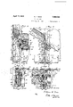
Figure 1 is adtransverse vertical sectional p view of a railway hopper car. l
Figure 2 is an enlarged view of the con- 5.3 struction illustrated in the lefthand portion of Figure 1.
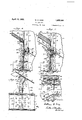
Figure 3 is an enlarged sectional view taken on line 3-3, Figure 1.
Figure 4 is an enlarged fragmentary sectional view taken'on line 4 4, Figure 1.
Figure 5 is a view corresponding to Figure 47 the floor sheets and onefof the side sheets of the car being omitted. Y
Figure 6 is a sectional view taken on line 65 6-6, Figure 2.
Figure 7 is a sectional view taken on line 7 7, Figure 2. n i
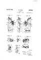
Figure 8 is an enlarged sectional view taken on line 8 8, Figure 1.
Figure 9 is a sectional view taken on line 99, Figure 8. y
Figure 10 isI a side elevational view of one of the members employed for connecting the bolster and side stakes.
Figure 11 is an end view of the member illustrated in Figure 10 as seen from the right hand side of that figure. y
Figure 12 is a side elevational view of the same member from the opposite side of that illustrated in Figure 10. v
Figure 13 is a side elevational view of one of the floor sheet supporting brackets.
Figure 14 is an end elevational view of this bracket as seen from the right hand side of Figure 13. y 1
Figure 15 is a side elevational view of the bracket taken from the opposite side of that shown in VFigure 13. y
Figure 16 is a plan view of the bracket. Figure 17 is a side elevational view of one of the brackets employed 4for bracing the iioor sheet supporting member of the bolster.
Figure 18 is an end view of this bracket as viewed from the right hand side of Figure 17.
Referring more particularly to the drawings the center sill beams, designated by lthe reference numeral 1, are each formed with upper and lower laterally projecting anges v webs 4 of the beams, are connected by a top cover plate 5.
Extending transversely of the car is a body bolster which,although it may be formed of a plurality of substantially vertical. plates, is preferably formed of a single verti-'cal plate 6 which extends continuously between side stakes 7 disposed on opposite sides ofthe car.
While the side stakes may be of any suitable v shape those illustrated in the drawings are of angle shape and each` is formed with a flange 8 for attachment by rivets 9 to an ad jacentside sheet 1() of the car 'and' with an inwardly extend-ing flange 11.',substantially` normal to the latter. The free or inner edge O'f. the flange 11 may be conveniently formed with a rigidifying bead or rib 12.
At its ends the belfster plate 6 is rigidly secu-red tothe inwardlyprojecting flanges 11 of the side stakes while at its lower central portion it i-srecessed or cut. away to receive the center sill structurer The lowerrportion o-f the bolster plate is preferably rigidified by two pairs of. angle members 13 disposed on opposite sides of thecenter sill. The members of. each pair having upstanding flanges 14 between Ywhich th-el adj oining portion. of the bolster plate is rigidly clamped by rivets 15 and laterally extending flanges 16 which proiject on opposite sides of the bolster plate. At their inner endsthe laterally extending flanges 16 rest uponand are secured by rivets 17 to the lower flanges 3 of the center sill while Vat their cuter ends they are overlappingly secured by rivets 18 to the inwardly extending flanges 19 of the adjacent angular 1y' shaped side sills 20.l The angle members 13 on one side of the center sill are preferably connected. to those on the other side by a bottom cover plate 21 which extends beneath the lower flanges 3 of the center sill and is secured to the lateral flanges 16of theangle members by rivets 22 and to the flanges 19 of the side sills by the rivets 18 heretofore mentifmed.v
T'o more rigidly connect the bolster plate to the center sill two pairs of` brackets 23 and 24 may be employed. Although the brackets of each pair are of substantially the same shape having flanges 25 and 26, respectively, brackets 24 extend from the lower portion of the center sill to the upper portionY of the bolster yplate while brackets 23 only extend from the lower to the upper portion of the center silli The flange 25 of each bracket overlaps and is rigidly secured by rivets 27 to the adjacent portions of the bolster plate while the Vflange 26 overlaps and is rigidly secured by rivets 28 to the web- 4 of the adjacent center sill beam. On the side of the bolster plate on which the brackets 23 are disposed is `a reinforcing angle member 29 which affords additional means Vfor connecting the bolster to the center sill. This member, which has flanges 30 and 31, extends across the top of the center sill and is bent downwardly on opposite sides of the latter for attachment to adjacent portions of the angle members 13. The flange V3() is secured to the bolster plate by rivets 32 while the flange 31 is secured to the top cover plate and the inwardly projecting flanges 2 of the center sill beams by rivets 33.
Intermediate the side stakes 7 the upper portion of the bolster plate 6 is bent as at 34 to afford a flange or portion 35 disposed in a plane ysubstantially normal to that of the inclined floor sheets 36 and 37 of the car. The ends of the inclined flangew35v of the bolster plate are integrally connected to those portions of the plate secured to the side stakes by portions 38 of substantially triangular shape and disposed in planes substantially parallel with the side sheets 10. Extending continuously along the upper portion of the bolster plate from adjacent one side stake to the other is an angularly shaped' member 39.y This member is formed with a flange or portion 40 parallel with the inclined floor sheets for supportingly cooperating with the latter and with a flange 41 normal to the floor sheets andsecured by rivets 42 to the inclined flange 35 of the! bolster plate. If desired, the outer or free edge of the flange 40 may be. formed with a rigidifying bead or flange 40?.
The floor sheets 36 and 37 have their adjoining ends disposed in overlapping Vrelation and each is secured to the flange 4f) by rivets 43. Along its side edges the floor sheet 37 is formed with upwardly projecting flanges 44 respectively rigidly secured to the adjacent portions of the flanges .8 of the side stakes and to the side sheets 1() in overlapping relation to the inner faces of each. The side sheets 10 extend below the plane of the floor sheet 37 and are rigidly secured to the upwardly extending legs 45 of the side sills 20.
The side sheets 10 extend beyond the sidev stakes to afford portions 46 to which adjoining side sheets 47 may be secured. At their lower portions the side sheets 47 are inclined downwardly and inwardly as at 48 and terminate in substantially vertical flanges 49 to which upwardly extending flanges 50, formed on the floor sheet 36, may be secured by rivets 51. The portions 48 which are inclined transversely of the car are in substantial alinement with the inwardly extending` flanges 11 of the side stakes so as to prevent lading from being pocketed by the stakes as it is being discharged from the car.
In order to reinforce the bolster at "the point where it is connected to the side stakes, members 52, preferably of cast metal, are employed. Each of these members is formed with a substantially vertical plate-like portion 53 having a plurality of offset portions 54, 55 and 56, all of which are rigidly secured to the inwardly extending fiange'11 of the adjacent side stake by rivets 57 The offset portion 54 contacts directly with the flange l1, the portion 55 contacts with the bolster plate6 and the portion 56 with the upstanding ange 14 of the adjacent angle member 13. .Thus it will be seen that the bolster plate is firmly clamped between the side stake and the reinforcing member 52. The plate portion 53 may conveniently extend beyond the the inner edge of the side stake so that additional rivets 58 may be employed for connecting it to the bolster.
Adjacent its upper portion the member 52 is formed with a laterally projecting angularly shaped portion 59 having flanges 60 and 61. The flange 60 projects on opposite sides of the plate portion 53 of the member and underlies the flange 40 of the adjoining end of the angularly` shaped member 39 of the bolster, being rigidly' secured theretoby a rivet 62 while the flange 61, which is normal tothe plane of the floor sheet overlaps and is rigidly secured, by rivets 63, to the adjoin-` ing end ofthe fiange 41 of the member 39. The rigidifyingl bead or flange 40a of the member 39 is, of course, cut away as at 64 inwardly of the angular portions 59 of the members 52 to permit the flanges 40 and 60 to be disposed in overlapping engagement. Theflange 60 may be conveniently formed with an upwardly projecting portion 65 adapted to engage the underside of the adjacent portion of the inclined floor sheet 36.
Along its outer edge the member 52 is formed with a laterally projecting flange 66 for attachment by rivets 67 to the projecting end portion 46 of the adjacent side sheet 10. The lower portion of the flange 66 is preferably inwardly offset to overlap the inner face of the vertical leg 45 of the adjacent side sill 20 for attachment thereto by rivets 68. The upper portion of the member 52 is designed to extend upwardly between the vertical flange 49 of` the adjacent side sheet 47 and the portion 46' of the side sheet 10. This upwardly extending portion of the member 52, designated by the reference numeral 69, is formed with a topflange inclined transversely as well as longitudinally of the car to supportingly cooperate with the inclined portion 48 of the adjacent side sheet 47. The flange 70 is integrally connected to the flange 66 and is also integrally joined with the flange 60 of the angular portion 59 by a substantially vertical wall or flange 71. Adj oining'portions of the side sheet 47 and the adjacent flange 50 of the floor sheet 36 are secured to the upwardly extending portion 69 of the member 52 by rivets 72 and 73 which respectively pass through flanges 70 and 71.
In order that the floor sheet 37 may extend beyond the inner edges of the side stakes it iscut away as at 74. Underlying this floor sheet adjacent its cut out portions are bracket members respectively formed withvertical portions 76 secured by two of the heretofore mentioned rivets 57 and with an inclined portion 77 for 'supporting portions of the floor sheet surrounding the adjacent cut out portion 74. These brackets not only serve to support the floor sheets but they prevent the escape of fine landing between the sheet and the side stake.
Each of the brackets 7 7 is formed with a laterally projecting portion 7 8`which extends beyond stake.V This portion is disposed in a plane substantially normal to `that of' the inclined floor sheets and is overlappinglysecured by the rivets 63 to the inclined flange 35 of the bolster'plate and the flange 41 of the angular member 39. Thus it will be seenthat the-angular member 39 is firmly clamped between the'brackets 75 and the members 52 which are respectively secured to opposite sides of the inwardly `extending flanges of the adjacent side stakes. By connecting the bolster to the side stakes in the manner described it will be readily perceived that a very strong and rigid construction is produced.
Although the neutral axis of the angular member 39 is preferably disposed in the plane of the vertical plate "of the bolster aplurality of brackets 79'may be conveniently employed for bracing it. Each of these brackets is formed with a portion 80y for attachment to the flange 40 of the member 39,' a portion 81 for attachment to the flange 41 of the latter` and a portion 824for attachment to the bolster plate. All of these portions are integrally connected by a laterally extending ange 83 disposed in a plane substantially normal to that of the bolster plate. By forming and arranging the brackets in this manner the angular member 39 is effectively braced. V
I claim:
1. In a railway car, the combination with an inclined floor sheet, of a body bolster having a substantially vertical plate portion extending transversely of the car, and an angularly shaped member extending along the top edge of said plate portion, said memberhaving a portion substantially parallel with the inclined fioor sheet and a portion substantially' .normal thereto, said inclined portion being in supporting cooperation with the floor sheet and having a downwardly extending Arigidifying flange.
2. In a railway car, kthe combination with side sheets andan inclined floor sheet, of side stakes respectively secured to said side sheets and having portions projecting inwardly therefrom, a body bolster having a substantially vertical plate projecting beyond the inner edges of the said portions of the side stakes and rigidly secured thereto, and an angularly shaped-member secured to the upper'portionofthebolster and extending continuously Yfrom a pointinwardly of the said portion of one side staketo a point inwardly of the said portionof the other side stake for supportingly cooperating with the floor sheet, said member having a portion disposed in a planesubstantially normal tothe fioor sheet anda yportion disposed in a plane substantially parallel thereto.
4. In a railway car, the combination with side stakes and an inclined floor sheet, of a body bolster rigidly secured to said stakes, said bolster having an angularly shaped member extending continuously fromadjacent one side stake lto the other for supporting the inclined floor sheet, and a separable member overlappingly secured to each side stake and the adjoining end of the angularly shaped member.
, 5. In a railway car, the combination with side sheets and an inclined floor sheet, of side stakes respectively secured to'said side sheets and having inwardly extending portions arranged substantially normal to the latter, a body bolster rigidly secured to the side stakes, said bolster having'an angularly shaped member extending continuously from adjacent one side staketo the other for supporting the inclined fioor sheet, and a separable member rigidly secured to the inwardly extending portion 'ofk each side stake and havingaportion projecting beyond the inner edge thereof, said Vprojecting portion being rigidly secured to the adjoining endl of said angularly shaped member.
6. In a railway car, the combination with side sheets andan inclined floor sheet, of side stakes respectively secured to said side sheets and having flanges extending inwardly therefrom, and a body bolster rigidly secured to the side stakes, said bolster having an angularly shaped member extending continuously from adjacent one side-stake to the other for supporting theY inclined floor sheet, and a member overlappingly secured to the flange of each stake and having a portion Y projecting inwardly therefrom, said portion being of angular shape "and rigidly secured to the adjoining end of said angular member. n
7.- In a railway car, the combinationwith side sheets and an inclined floor sheet, of side stakes respectively secured to said side'sheets and having flanges extending inwardly therefrom, a body bolsterrigidly secured to said .ly therefrom, a body bolster lrigidly secured to said side stakes,YY an angularly shapedV member extending continuously from adjacent one side stake to the other,said member having a -portion substantially normal to the floor sheet and rigidly secured to the bolster and a portion-substantially parallel to the c floor sheet for supporting the latter, and a member overlappingly secured to the fiange 'of each 'side stake and having portions overlappingly secured to both of said portions of the angularly shaped member.
9. In a railway car, thev combination with side sheets and an inclined floor sheet, of side stakes respectively secured to said side sheets and having flanges extending inwardly therefrom, a body bolster rigidly secured to said side stakes, an angularly shaped member secured to the bolster and extending-continuously from adjacent one side stake to the other, said member having a portion disposed in a plane substantially parallel to the floor sheet for supporting the latter, and a member rigidly secured to the flange of each side stake 4and having a portion underlying and rigidly secured to the said portion of the angularly shaped member. v
10. In a railway car, the combination withY an insideside stake, of a side sheet and floor sheet, one of said sheets having a portion inclined transversely of the car in alinement with the side stake, a body bolster rigidly secured to said side stake, and an integral member rigidly secured to the side stake andthe adjoining end of the bolster, said member having an inclined portion underlying and supporting the said transverse incline of one of said sheets.
ll. In a railway car,the combination with side sheets and an inclined floor sheet, of side stakes respectively secured to said side sheets l and having flanges extending inwardly from portion substantially parallel thereto, and a the latter, a body bolster rigidly secured to plurality of angularly shaped brackets sesaid side stakes, said bolster having an angucured to the parallel portion of said member larly shaped member extending along its up- :for bracing the latter, said brackets being per edge and terminating inwardly of the also secured to the normal portion of the said side stakes, and an integral member rigidly member and the plate of the bolster. Secured to the flange of each side stake and In testimony whereof I affix my signature. the adjoining side sheet, each integral mem- WILLIAM E. WINE.
ber having a portion rigidly secured to the adjoining end of the said angular member of 75 the bolster.
12. In a railway car, the combination with side sheets and an inclined floor sheet, of side stakes respectively secured to said side sheets' and having flanges extending inwardly from Y the latter, a body bolster rigidly secured t0 said side stakes, an angularly shaped member secured to the bolster and extending continuously from adjacent one side stake to thev other, and an integral member secured to 85 the flange of each side stake and having an inclined surface for supporting an inclined portion of an adjacent sheet of the car, said integral member being formed with a laterally projecting portion extending beyond v 90 the inner edge of the flange of the adjacent side stake and rigidly secured to the adjoining end of the angle shaped member.
13. In a railway car, the combination with side sheets and inclined floor sheets, of side j stakes secured to the side sheets and having flanges extending inwardly from the latter, a body bolster rigidly secured to the side stakes, an angularly shaped member secured H to the bolster and extending continuously i from adjacent one side stake to the other for supporting the inclined loor sheets, said member having a portion disposed in a plane substantially normal to the floor sheets, and Y members secured to opposite sides of the 105 fiange of each stake and respectively having portions rigidly secured to the said normal portion of the angularly shaped member.
14. In a railway car, the combination with an inclined floor sheet, of a body bolster hav- A n 110 ing a substantially vertical web portion extending transversely of the car, said bolster being provided with a` portion susbtantially normal to the inclined floor sheet and a por- .m tion substantially parallel thereto, said parallel portion extending on opposite sides of the vertical web of the bolster and being adapted to supportingly cooperate with the. floor sheet, and means rigid with said web ing the latter, said means including a flange substantially normal to the web.
15. In a railway car, the combination with an inclined floor sheet, of a body bolster hav- Y ing a substantially vertical plate extending p i 125 transversely of the car, an angularly shaped i member secured to the upper portion of the bolster for supportingly cooperating with the floor sheet, said member having a portion substantially normal to the floor sheet and a f and parallel portion of the bolster Jfor brac- 120y
Priority Applications (1)
| Application Number | Priority Date | Filing Date | Title |
|---|---|---|---|
| US457357A US1855080A (en) | 1930-05-29 | 1930-05-29 | Railway car |
Applications Claiming Priority (1)
| Application Number | Priority Date | Filing Date | Title |
|---|---|---|---|
| US457357A US1855080A (en) | 1930-05-29 | 1930-05-29 | Railway car |
Publications (1)
| Publication Number | Publication Date |
|---|---|
| US1855080A true US1855080A (en) | 1932-04-19 |
Family
ID=23816406
Family Applications (1)
| Application Number | Title | Priority Date | Filing Date |
|---|---|---|---|
| US457357A Expired - Lifetime US1855080A (en) | 1930-05-29 | 1930-05-29 | Railway car |
Country Status (1)
| Country | Link |
|---|---|
| US (1) | US1855080A (en) |
Cited By (1)
| Publication number | Priority date | Publication date | Assignee | Title |
|---|---|---|---|---|
| US2559760A (en) * | 1948-08-17 | 1951-07-10 | Entpr Railway Equipment Co | Hopper car door frame |
-
1930
- 1930-05-29 US US457357A patent/US1855080A/en not_active Expired - Lifetime
Cited By (1)
| Publication number | Priority date | Publication date | Assignee | Title |
|---|---|---|---|---|
| US2559760A (en) * | 1948-08-17 | 1951-07-10 | Entpr Railway Equipment Co | Hopper car door frame |
Similar Documents
| Publication | Publication Date | Title |
|---|---|---|
| US1855080A (en) | Railway car | |
| USRE17542E (en) | O o o o o o | |
| US1962717A (en) | Freight car | |
| US1552585A (en) | Manure spreader | |
| US2197708A (en) | Car body | |
| US2020391A (en) | Railway car | |
| US2072996A (en) | Railway hopper car | |
| US2104359A (en) | Railway car | |
| US1455867A (en) | Metal car structure | |
| US2033566A (en) | Cross bearer side stake | |
| US723067A (en) | Metallic car. | |
| US2060157A (en) | Railway car | |
| US2504658A (en) | Body construction, especially for railway cars | |
| US2352718A (en) | Draft gear backstop and center filler | |
| US1956302A (en) | Railway car | |
| US2014725A (en) | Mine car | |
| US2060156A (en) | Railway hopper car | |
| US2197443A (en) | Railway hopper car | |
| US2185976A (en) | Underframe | |
| US728800A (en) | Car construction. | |
| US2150417A (en) | Railway car underframe | |
| US1861730A (en) | Railway car | |
| US1691474A (en) | Car-frame construction | |
| US2528479A (en) | Center filler | |
| US1799270A (en) | Brace and cross-bearer for freight cars |