US1855071A - Steering meter - Google Patents
Steering meter Download PDFInfo
- Publication number
- US1855071A US1855071A US565682A US56568231A US1855071A US 1855071 A US1855071 A US 1855071A US 565682 A US565682 A US 565682A US 56568231 A US56568231 A US 56568231A US 1855071 A US1855071 A US 1855071A
- Authority
- US
- United States
- Prior art keywords
- wheels
- vehicle
- casing
- arm
- shaft
- Prior art date
- Legal status (The legal status is an assumption and is not a legal conclusion. Google has not performed a legal analysis and makes no representation as to the accuracy of the status listed.)
- Expired - Lifetime
Links
- 230000007775 late Effects 0.000 description 3
- 101000619542 Homo sapiens E3 ubiquitin-protein ligase parkin Proteins 0.000 description 1
- 238000010276 construction Methods 0.000 description 1
- 239000002184 metal Substances 0.000 description 1
- 230000004048 modification Effects 0.000 description 1
- 238000012986 modification Methods 0.000 description 1
- 102000045222 parkin Human genes 0.000 description 1
Images

Classifications
-
- B—PERFORMING OPERATIONS; TRANSPORTING
- B62—LAND VEHICLES FOR TRAVELLING OTHERWISE THAN ON RAILS
- B62D—MOTOR VEHICLES; TRAILERS
- B62D15/00—Steering not otherwise provided for
- B62D15/02—Steering position indicators ; Steering position determination; Steering aids
Definitions
- My present invention has reference to a front wheel angle indicator for automobiles or like vehicles.
- An object of the/invention is to arrange upon the instrument board of an automobile or like-vehicle an indicator having a representation thereon of the plan of the vehicle on which it is installed, the front wheels and the ground surface over which the wheels travel when the vehicle is driven in a straight direction, together with angle scales atl the opposite sides of the road indicating surface and together with means connected with the steering gear of the vehicle and the mechanism on the casing for causing the wheels of the miniature plan of the vehicle in the casing to turn simultaneously with and in the same direction of the turning of the wheels of the vehicle and whereby the driver ⁇ will have visible indication as to the exact angles the front wheels are turned and further whereby the driver, when parked in a small space fmay, without necessitating his constant observation of the round conditions, the vehicle to the front o?, the vehicle of his machine, extricate himself from the parking space without liability of danger to his car or vehicle or to those to the front and rear thereof and also wherein the device may be employed to indicate unnecessary loose play in the steering wheels of the automobile.
- a further and important object of the invention is the provision of an indicator for this purpose t at is characterized by sim-A 3" licity in construction, cheapness in manuacture, ease in application and reliability and efliciency in practical use.
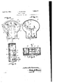
- Figure 1 is a side elevation of the front portion of a vehicle equipped with the im,-
- Figure 2 is a top plan view of the front run-- Figure 5 is a sectional view approximately on the line 5--5 of Figure 3. y
- Figure 6 is a sectional view approximatelyr i on the line 6--6 of Figure 3.
- Figure 7 is a sectional view ap roximately similar to Figure 5 but illustrating a slight modification.
- the numeral 1 designates the front axle of an automobile or like vehicle which has pivotally mounted on its ends the knuckles for the spindles for the front wheels 2.
- the spindles are provided with the usual arms 3 to which are connected the ends of the rod 4.
- the rod 4 is operated in the usual manner and, of course, imparts simultaneous swingingto the wheels 2.
- the casing 8 is secured upon the instrument board of the machine and the same preferably has an upper elliptical portion and a lower reduced rectangular portion.
- the front of the frame is removable and has arranged therein a transparent plate or window 9, corresponding, of course, to the shape of the casing to the rear of the transparent plate 9.
- the plate 10 has ⁇ inscribed thereon blocks or bars- 13 which indicate the roadway over which the machine travels and the miniature wheels 12 have their sides arranged in a line with the sides or edges of the bars 13 when the vehicle is traveling in a straight ahead direction.
- the plate .10 has inscribed thereon degree marks 14, respectively,I which are'arranged at the opposite sides of the bars 13. When the miniature wheels 12 have turned they will v his machine.
- The' miniature wheels 12 are really in the nature 'of metal lates whichl have their ends rounded and w ich like the miniature vehicle 11 are colored.
- Each of the plates 12 has fixed thereto .and journaled to the late 10 a short shaft 15 andto each of these s afts there is fixed a depending link 16.
- the links are connected by a bar 17 and tothe pivot connecting the bar to one of thellnks there is attached another link 18.
- the inner end of the rod or shaft 7 is reduced, and received in a ybearing openin in the center of a substantially U-shaped racket 20 which 1s fixedly secured in the casing 8.
- therod or shaft 7 similar to the rod or shaft 7 has on the end thereof which enters the casin 8 a beveled pinion 21 which is in mesh wit a similar inion 22 that is fixed on a shaft 23, the sai shaft having reduced ends which arejournaled in bearing openings in the rear wall of the indicator casing and in a bracket 24 substantially similar to the bracket 20.
- the short shaft 23 has fixedly secured thereto an arm 25 which is similar to the arm 19 and which arm is connected to the elements for imparting a swinging or angular movement to the miniature wheels above described.
- the link 18 is 'to travel when the vehicle isin a straightahead direction, the bars representing the wheels bein pivotally supported and means between an operated by the steering mechanism for the front wheels for turning the miniature wheels simultaneously with and at the same angle as that assumed by the front wheels ofthe vehicle, and said indicator havlng further inscribed thereon degree scales vhich extend from the opposite sides of the ars.
- a front wheel angle indicator for automobiles including a casing to be lixedly supported on the instrument board orfat the ront of an automobile, said casing having inscribed thereon a replica of the automobile in which the front wheels of the replica are in the nature of (plates, and which indicator has also inscribe thereon bars representing the paths on which the wheels are supposed to travel when the vehicle is in a straightahead direction, the bars representing the wheels beingr pivotally supported and means between an operated by the steering mechanism for the front wheels for turning the 'miniature wheels simultaneously with and at the same angle as that assumed by the front wheels of the vehicle, said means including links secured to the pivots, a bar connecting the links, an angularly arranged link pivotally secured to one end of the bar, an arm to which Ithe last named link is pivoted, a shaft journaled in the casing and on which the arm is fixed, an angle arm on the outer end of the shaft, and a rod member connected to the arm and to one of the spindle arms for the front wheelof the automobile.
- a front wheel angle indicator for automobiles including a casing to be fixedly supported on the instrument board or at the front of an automobile, said casing having inscribed thereon al replica of the automobile in which the front wheels of the replica are in the nature of lates, and which indicator has also inscribed) thereon bars representing the paths on which the wheels are supposed to travel when the vehicle is in a straightahead direction, the bars representing the wheels being pivotally supported, means between and operated by the steering mecha- .”iism for the front wheels for turning the miniature wheels simultaneously with and at the same angle as that assumed-by the font wheels of the vehicle, said means compriscing links secured to the pivots, a.
Landscapes
- Engineering & Computer Science (AREA)
- Chemical & Material Sciences (AREA)
- Combustion & Propulsion (AREA)
- Transportation (AREA)
- Mechanical Engineering (AREA)
- A Measuring Device Byusing Mechanical Method (AREA)
Description
April 19, 1932. 1 STEFANSON 1,855,071
STEERING METER Filed Sept. 28, 1931 2 Sheets-Sheet l ATTOR NEV J. STEFANSON STEERING METER April 19, 1932.
Filed Sept. 2 8, 1931 2 Sheets-Sheet 2 a In 9 @Fly Jahneamo Q :NVEN'roR M ATTORNEY WITNESS:
Patented Apr. 19, 1932..
. lnivrr-:N'rY OFI-1c JOHN STEFANSON, OF CALISTOGA, CALIFORNIA.
STEERING METER Application led September 28, 1931. Seriallo. 565,682.
My present invention has reference to a front wheel angle indicator for automobiles or like vehicles. I
An object of the/invention is to arrange upon the instrument board of an automobile or like-vehicle an indicator having a representation thereon of the plan of the vehicle on which it is installed, the front wheels and the ground surface over which the wheels travel when the vehicle is driven in a straight direction, together with angle scales atl the opposite sides of the road indicating surface and together with means connected with the steering gear of the vehicle and the mechanism on the casing for causing the wheels of the miniature plan of the vehicle in the casing to turn simultaneously with and in the same direction of the turning of the wheels of the vehicle and whereby the driver `will have visible indication as to the exact angles the front wheels are turned and further whereby the driver, when parked in a small space fmay, without necessitating his constant observation of the round conditions, the vehicle to the front o?, the vehicle of his machine, extricate himself from the parking space without liability of danger to his car or vehicle or to those to the front and rear thereof and also wherein the device may be employed to indicate unnecessary loose play in the steering wheels of the automobile.
A further and important object of the invention is the provision of an indicator for this purpose t at is characterized by sim-A 3" licity in construction, cheapness in manuacture, ease in application and reliability and efliciency in practical use.
To the attainment of the foregoing the invention consists in the improvement hereinafter described and definitely claimed.
In the drawings:
Figure 1 is a side elevation of the front portion of a vehicle equipped with the im,-
prove'ment.
5 .onthe nner-401 Figure 5. l
Figure 2 is a top plan view of the front run-- Figure 5 is a sectional view approximately on the line 5--5 of Figure 3. y
Figure 6 is a sectional view approximatelyr i on the line 6--6 of Figure 3.
Figure 7 is a sectional view ap roximately similar to Figure 5 but illustrating a slight modification. v
Referring now to the drawings the numeral 1 designates the front axle of an automobile or like vehicle which has pivotally mounted on its ends the knuckles for the spindles for the front wheels 2. The spindles are provided with the usual arms 3 to which are connected the ends of the rod 4. The rod 4 is operated in the usual manner and, of course, imparts simultaneous swingingto the wheels 2.
Secured to one of the arms 3 there is a rod or arm 5 directed toward the center ofthe axle 1 and whose end is loosely connected with a swingable arm 6 which is pivotally supported upon a rod 7. The rod 7 is journale'd in suitable bearings and enters the rear of the casing of the improvement. The casing 8 is secured upon the instrument board of the machine and the same preferably has an upper elliptical portion and a lower reduced rectangular portion. The front of the frame is removable and has arranged therein a transparent plate or window 9, corresponding, of course, to the shape of the casing to the rear of the transparent plate 9. There is secured in the casmg a non-transparent plate 10 and on the lower portion of Ithis plate there is delineated the body 11 of a miniature vehicle representing the vehicle upon'.
which the indicator is applied. The front mud guards of the miniature vehicle are removed so that the front wheels 12 thereof are clearly observable. The plate 10 has `inscribed thereon blocks or bars- 13 which indicate the roadway over which the machine travels and the miniature wheels 12 have their sides arranged in a line with the sides or edges of the bars 13 when the vehicle is traveling in a straight ahead direction. The plate .10 has inscribed thereon degree marks 14, respectively,I which are'arranged at the opposite sides of the bars 13. When the miniature wheels 12 have turned they will v his machine.
turn in the direction ofthe scales 14 and will indicate to the driver the degree or -an le which the front wheels 2 of the vehicle ta e, the front wheels 2, of course, being turned b the usual steering wheel and the mechanlsm associated therewith.
The' miniature wheels 12 are really in the nature 'of metal lates whichl have their ends rounded and w ich like the miniature vehicle 11 are colored. Each of the plates 12 has fixed thereto .and journaled to the late 10 a short shaft 15 andto each of these s afts there is fixed a depending link 16. The links are connected by a bar 17 and tothe pivot connecting the bar to one of thellnks there is attached another link 18. I arranged at a downward an le with respect to the connecting bar or ro 17 and has its outer end pivotally secured to a throw arm 19 and this arm has its lower end fixedly secured to the shaft or rod 7. The inner end of the rod or shaft 7 is reduced, and received in a ybearing openin in the center of a substantially U-shaped racket 20 which 1s fixedly secured in the casing 8.
From the foregoin descrlptlon when read in connection with t e accompanyin drawings it will be apparent that when t e front wheels 2 of the vehicle are turned the mimature wheels 12 in the indicator casing'will be simultaneously turned in the same direction as that of the wheels 2. This will indicate to the driver the exact angular arrangement of the front wheels and will permit him extricatin his vehicle lfrom ,small parking spaces witout necessitating his 'constant observing the vehicles at the front or rear of This not only results in the saving of time in moving into or out of parkin spaces but obviates the liablllty of the ve icle contacting with the parked machines. Also the improvement will indicate any unnecessary or undesirable looseness in the front wheels 2 of the automobile.
In instances where the instrument board of the vehicle ,is arranged in vertical position therod or shaft 7 similar to the rod or shaft 7 has on the end thereof which enters the casin 8 a beveled pinion 21 which is in mesh wit a similar inion 22 that is fixed on a shaft 23, the sai shaft having reduced ends which arejournaled in bearing openings in the rear wall of the indicator casing and in a bracket 24 substantially similar to the bracket 20. The short shaft 23 has fixedly secured thereto an arm 25 which is similar to the arm 19 and which arm is connected to the elements for imparting a swinging or angular movement to the miniature wheels above described.
While I have illustrated a satisfactory embodiment of my improvement my features of invention are capable of extended ap lication and I do not wish to be restricte .to
`the precise details herein set forth and, there- The link 18 is 'to travel when the vehicle isin a straightahead direction, the bars representing the wheels bein pivotally supported and means between an operated by the steering mechanism for the front wheels for turning the miniature wheels simultaneously with and at the same angle as that assumed by the front wheels ofthe vehicle, and said indicator havlng further inscribed thereon degree scales vhich extend from the opposite sides of the ars.
2. A front wheel angle indicator for automobiles, including a casing to be lixedly supported on the instrument board orfat the ront of an automobile, said casing having inscribed thereon a replica of the automobile in which the front wheels of the replica are in the nature of (plates, and which indicator has also inscribe thereon bars representing the paths on which the wheels are supposed to travel when the vehicle is in a straightahead direction, the bars representing the wheels beingr pivotally supported and means between an operated by the steering mechanism for the front wheels for turning the 'miniature wheels simultaneously with and at the same angle as that assumed by the front wheels of the vehicle, said means including links secured to the pivots, a bar connecting the links, an angularly arranged link pivotally secured to one end of the bar, an arm to which Ithe last named link is pivoted, a shaft journaled in the casing and on which the arm is fixed, an angle arm on the outer end of the shaft, and a rod member connected to the arm and to one of the spindle arms for the front wheelof the automobile.
3. A front wheel angle indicator for automobiles, including a casing to be fixedly supported on the instrument board or at the front of an automobile, said casing having inscribed thereon al replica of the automobile in which the front wheels of the replica are in the nature of lates, and which indicator has also inscribed) thereon bars representing the paths on which the wheels are supposed to travel when the vehicle is in a straightahead direction, the bars representing the wheels being pivotally supported, means between and operated by the steering mecha- ."iism for the front wheels for turning the miniature wheels simultaneously with and at the same angle as that assumed-by the font wheels of the vehicle, said means compriscing links secured to the pivots, a. bar pivotally secured to the links, an angle link pivotally connected to one end of the bar, an arm pivoted to the angle link, a shaft journaled in bearings in the casing on which the arm is fixed, a beveled gear on the shaft, a second and angularly arranged shaft having one end j ournaled in the casing and'having a gear to mesh with the firstnamed gear, an angle arm on the end of the last named shaft and a rod connection between the armand the spindle i arm of one of the front wheels of the automobile.
In testimony whereof I aix my signature. JOHN STEFANSON.
Priority Applications (1)
| Application Number | Priority Date | Filing Date | Title |
|---|---|---|---|
| US565682A US1855071A (en) | 1931-09-28 | 1931-09-28 | Steering meter |
Applications Claiming Priority (1)
| Application Number | Priority Date | Filing Date | Title |
|---|---|---|---|
| US565682A US1855071A (en) | 1931-09-28 | 1931-09-28 | Steering meter |
Publications (1)
| Publication Number | Publication Date |
|---|---|
| US1855071A true US1855071A (en) | 1932-04-19 |
Family
ID=24259669
Family Applications (1)
| Application Number | Title | Priority Date | Filing Date |
|---|---|---|---|
| US565682A Expired - Lifetime US1855071A (en) | 1931-09-28 | 1931-09-28 | Steering meter |
Country Status (1)
| Country | Link |
|---|---|
| US (1) | US1855071A (en) |
Cited By (2)
| Publication number | Priority date | Publication date | Assignee | Title |
|---|---|---|---|---|
| US2425762A (en) * | 1943-11-22 | 1947-08-19 | Stone Albert Rivington | Azimuth indicator |
| US2439476A (en) * | 1946-02-11 | 1948-04-13 | Guy O Leggett | Indicator |
-
1931
- 1931-09-28 US US565682A patent/US1855071A/en not_active Expired - Lifetime
Cited By (2)
| Publication number | Priority date | Publication date | Assignee | Title |
|---|---|---|---|---|
| US2425762A (en) * | 1943-11-22 | 1947-08-19 | Stone Albert Rivington | Azimuth indicator |
| US2439476A (en) * | 1946-02-11 | 1948-04-13 | Guy O Leggett | Indicator |
Similar Documents
| Publication | Publication Date | Title |
|---|---|---|
| US1855071A (en) | Steering meter | |
| US2814499A (en) | Automobile steering device | |
| US1577559A (en) | Motor vehicle | |
| US2175637A (en) | Index mechanism for the steering wheels of carriages | |
| US1225737A (en) | Steering mechanism for automobiles. | |
| US1470617A (en) | Direction indicator | |
| US2057322A (en) | Front box fender | |
| US1451795A (en) | Direction signal for automobiles | |
| US1939453A (en) | Motor operated automobile steering machine | |
| US2058176A (en) | Automobile signal | |
| US1217105A (en) | Steering-wheel indicator. | |
| US1438042A (en) | Steering gear for automobiles | |
| US1794014A (en) | Automobile stop and turning signal | |
| US1403082A (en) | Traffic-signaling means for vehicles | |
| US1328762A (en) | Steering-gear attachment | |
| US1583378A (en) | Spindle bracket | |
| US1234831A (en) | Direction-indicator for automobiles. | |
| US1547499A (en) | Dirigible headlight | |
| US1614279A (en) | Steering device for vehicles | |
| US1390094A (en) | Automobile-signal | |
| US1495899A (en) | Automobile signal | |
| US1480816A (en) | Direction indicator for automobiles | |
| US935855A (en) | Vehicle-signal. | |
| US1708218A (en) | Automobile directional signal | |
| US1736485A (en) | Direction-signaling device for vehicles |