US1855067A - Automobile brake - Google Patents
Automobile brake Download PDFInfo
- Publication number
- US1855067A US1855067A US378135A US37813529A US1855067A US 1855067 A US1855067 A US 1855067A US 378135 A US378135 A US 378135A US 37813529 A US37813529 A US 37813529A US 1855067 A US1855067 A US 1855067A
- Authority
- US
- United States
- Prior art keywords
- diaphragm
- casing
- brake
- section
- pedal
- Prior art date
- Legal status (The legal status is an assumption and is not a legal conclusion. Google has not performed a legal analysis and makes no representation as to the accuracy of the status listed.)
- Expired - Lifetime
Links
- 238000013022 venting Methods 0.000 description 5
- 210000002445 nipple Anatomy 0.000 description 4
- 238000002485 combustion reaction Methods 0.000 description 3
- 230000000994 depressogenic effect Effects 0.000 description 3
- 238000010276 construction Methods 0.000 description 2
- 230000008878 coupling Effects 0.000 description 2
- 238000010168 coupling process Methods 0.000 description 2
- 238000005859 coupling reaction Methods 0.000 description 2
- YKMMLFOYDTYAGR-UHFFFAOYSA-N 1-phenyl-2-(propan-2-ylamino)pentan-1-one Chemical compound CCCC(NC(C)C)C(=O)C1=CC=CC=C1 YKMMLFOYDTYAGR-UHFFFAOYSA-N 0.000 description 1
- 240000001973 Ficus microcarpa Species 0.000 description 1
- 230000015572 biosynthetic process Effects 0.000 description 1
- 230000000881 depressing effect Effects 0.000 description 1
- 238000004519 manufacturing process Methods 0.000 description 1
- 230000001360 synchronised effect Effects 0.000 description 1
Images

Classifications
-
- B—PERFORMING OPERATIONS; TRANSPORTING
- B60—VEHICLES IN GENERAL
- B60T—VEHICLE BRAKE CONTROL SYSTEMS OR PARTS THEREOF; BRAKE CONTROL SYSTEMS OR PARTS THEREOF, IN GENERAL; ARRANGEMENT OF BRAKING ELEMENTS ON VEHICLES IN GENERAL; PORTABLE DEVICES FOR PREVENTING UNWANTED MOVEMENT OF VEHICLES; VEHICLE MODIFICATIONS TO FACILITATE COOLING OF BRAKES
- B60T13/00—Transmitting braking action from initiating means to ultimate brake actuator with power assistance or drive; Brake systems incorporating such transmitting means, e.g. air-pressure brake systems
- B60T13/10—Transmitting braking action from initiating means to ultimate brake actuator with power assistance or drive; Brake systems incorporating such transmitting means, e.g. air-pressure brake systems with fluid assistance, drive, or release
- B60T13/24—Transmitting braking action from initiating means to ultimate brake actuator with power assistance or drive; Brake systems incorporating such transmitting means, e.g. air-pressure brake systems with fluid assistance, drive, or release the fluid being gaseous
- B60T13/46—Vacuum systems
- B60T13/48—Vacuum systems direct, i.e. brakes applied directly by vacuum
Definitions
- This invention relates to brakes for vehicles and more particularly to a vacuum brake for automobiles.
- One of the primary objects of my invention is to provide a novel brake for automobiles so constructed as to eliminate the necessity of providing the usual brake rigging, the invention embodying a diaphragm for the brake shoes of each brake drum with novel means under the control of the operator of the vehicle for actuating the diaphragm.
- Another important object of my invention is the provision of a vacuum brake for automobiles, embodying a suction operated master diaphragm having operative connection through the medium of suitable suction pipes with independent suction operated diaphragms, for the brake shoes ofeach wheel of the vehicle with means actuated by the brake pedal for lcontrolling the suction through the master diaphragm.
- a vacuum brake for automobiles'embodying a master diaphragm connected by a suction pipe with the intake manifold of the internal combustion engine of the vehicle, whereby the master diaphragm can be actuated fromthe vehicle, the suction pipe having interposed in the length thereof a three-way valve normally closing the suction through the pipe and for establishing atmospheric communication with the master diaphragm, and a brake pedal having connection with the diaphragm and with said three-way valve whereby, upon downward pressure upon the brake pedal, the diaphragm will be raised thereby, and the three-way valve .actuated to establish communication between the manifold and the master diaphragm for causing a suction on said diaphragm and thereby actuate the same, the master diaphragm being connected with brake shoe actuating diaphragms by suitable suction pipes.
- a still further object of my invention is to provid-e an improved vacuum brake of the 5'5 above character which will be durable and efficient in use, one which is simple and easy to manufacture, and one which can be incorporated with an automobile at a low cost.
- the invention consists in the novel construction, arrangement and formation of parts, as will 'be hereinafter more specifically described,
- Fig. 2 is a fragmentary side elevation of my improved device, illustrating the connec- .1 tion between the brake pedal and the foot 7o board of a motor vehicle, the foot board being shown in section.
- Fig. 3 is a detail ⁇ central yertical section through the master control device or'dial. phragm, showing the same in its normal in- 75 operative position.
- Fig. 4 is a detail sectional view illustrating the means of connecting the main suc.- tion pipe for themastercontrol device with f, the intake manifold of the internal combustion engine.
- FIG.,5 is a detail side elevation of one of the brake shoe operating diaphragms.
- Fig.. 6 is a vertical section taken on th line 6 6 of Fig. 5.
- Fig. 7 is a central vertical section thru one of the brake operating diaphragms.
- Fig. 8 is a'detail sectional view through the three-way valve employed for controlling m the 4operation of the master control dia- '90 phragm device.
- Fig. 9 is a detail longitudinal section thru said valve in the position whereby communication between the master control device and the engine manifoldis established.
- Figure 10 isl a fragmentary detail view in longitudinal section showing the joints connecting the two sections of the foot pedal arm.
- Figure 11 s a detail longitudinal sectional i view through the three-way valve showing same in position for venting the master control device or diaphragm to atmosphere.
- the letter A generally indicates my improved vacuum brake, which comprises a main control device'or diaphragm 10.
- the main control device or diaphragm 10 embodies a casing 11 including upper and lower companion casing sections 12 and 13 having formed at their peripheries attaching flanges 15. These flanges 15 receive therebetween the flexible' body or diaphragm proper 16. I preferably place the diaphragm proper 16, between spacing rings 17 and sealin washers 18 can be interposed between said rings and the flanges 15.
- Suitable bolts 19 are passed through the flanges 15, the washers 18, and the rings 17 for holding the -sections of the casing 10 assembled in position.
- the section 12 of the casing 11 is provided with an axially disposed boss 20 through which slidably extends the diaphragm rod 21.
- t-hel rod 21 is connected in any desired way, as at 23 at the axial center of the diaphragm proper 16.
- section 12 of the casing 11 is provided with an internally threaded nipple 24, having connected therewith a suction pipe 25.
- An expansion spring 26 is placed about the diaphragm rod 21 and engages the diaphragm 16 and the inner surface of the section 12 of the casing, and normally functions to hold the diaphragm in its lowered, or inoperative position.
- An outlet suction nipple 27 is formed on the section 13 of the casing 11 below the diaphragm 16.
- a suitable four-way coupling 28 having connected therewith branch pipes 29, 30, 31, and 32 each of which leads to a diaphragm device 34.
- the auxiliary diaphragm devices 34 each include a sectional casing 35 having clamped between the sections thereof the llexibledi-
- each casing 35 is provided with an axial opening 38 through which extends a rod 39 connected as at 40 with the axial center of the diaphragm.
- the rods 39 are operatively connected to the brake shoes of the vehicle in any .preferred way.
- a supporting bracket 41 which can beliolted to the casing 35 of each diaphragm device 34, and this bracket is connected to the rod 39 by a contractile coil spring 42, which functions to normally hold the diaphragm in the position shown in Fig. 7 and the brakes in their released position.
- the upper end of the diaphragm rod 21 thereof is pivotally connected as at 43 with the lower end of the brake pedal 44.
- This brake pedal 44 is rockably mounted at a point Within and intermediate its ends on a suitable bracket 45 which can be secured to the casing 11 of the master control device 10 or to any suitable part of the vehicle.
- the device 10 is to be secured on the chassis of the vehicle in any desired manner.
- the brake pedal extends below the floor boards 46 of the vehicle in the usual way, and is provided with a foot piece 47 to facilitate the operation thereof. From the construction so far, it can be seenthat when the brake pedal is depressed that the rod 21 will be drawn upwardly.
- the outer pedal section is connected to the floor board 46 by a retractile coil spring 49 and thus the brake pedal is normally held in a raised position, with the brakes in their released position.
- the pipe 25 is connected, preferably by a flexible hose 50, with a tap 51 connected with the intake manifold 52 lof the internal combustion engine of the automobile, and the pipe 25 has interposed in the length thereof a. three-way valve 53.
- the valve 53 is provided with an atmosphere port 54 and includes a rotatable valve plug 55 having communicating passages-56 and 56.
- the plug has secured thereto an operating crank' 57 which is, in turn, operatively connected to the brake pedal 44, as at 58, said connection including a sleeve 58 slidable on the pedal 44 and to which the crank 57 is pivotally connected.
- valve plug is disposed with the passage 56 in a vertical position, as seen in Figure 11 for closing communication between the master controly device 10 and the manifold 52.
- the plug 55 will be rotated to the position shown in Fig. 9 establishing full communication between the upper end of the master control device and the intake manifold, creating a suction on the upper face of the diaphragm proper 16, causing the raising there-
- the working parts of the device are normally disposed as illustrated in Figs. 3- and 7 of the drawin s, and when it is desired to apply the bra e, the pedal 44 is depressed, which will lift up on lthe rod 21 and. move the flexible di7aphragm proper 16 away from the nipp
- the master control device 10 will be vented to atmosphere during the initial upward movement of the diaphragm 16 as long as the passage 56 is in communication with the port 54 of the valve 53.
- This initial movement of the diaphragm 16 is usually suiiicient to cause the desired application of the vehicle bra-kes. Raising of the diaphragm proper will cause a suction on the various pipes 29, 30, 32, and 33. This will create a suction within the auxiliary diaphragm devices 34 and the diaphragm 36 will be moved inward therein, thereby causing a pull on the rod 39 for applying the brakes.
- this movement of the brake pedal is generally suflicient to apply the brakes to bring the vehicle to a halt, but should it be desired to apply the brakes quicker or With more force, the brake pedal may be pushed farther down, which will move the valve plug 55'to the position shown in Fig. 9 of the drawings,establishing complete communication between the intake manifold and the upper end of the master control device 10. This suction from the force of the diaphragm 16 which will create a greater suction in the various pipes, 29, 30, 31 and 32.
- a braking mechanism for motor vehicles comprising a casing, a diaphragm operatively mounted in the casing a suction pipe connecting the casing with the intake manifold of the vehicle engine for actuating the diaphragm, a multiway valve interposed in the pipe for selectively establishing communication between the casing and the manifold and between the casing and the atmosphere for venting the casing a rod fixed to the diaphragm and extending slidably through the casing, a foot pedal pivotally supported intermediate its ends on the casing and having one end pivotally connected to the rod for sto manually actuating the diaphragm, a crank arm having one end fixed to the valve and its other end pivotally and slidably connected to the foot pedal for operating the valve upon actuation of the foot pedal, and brake operating means operatively connected to the casing for actuation by the diaphragm.
- a braking mechanism for motor vehicles comprising a casing, a diaphragm operatively mounted in the casing,a suction pipe connecting the casing with the intake manifold of the vehicle engine for actuating the diaphragm, a multiway valve interposed in the suction pipe for selectively establishing communication between the casing and the manifold and between the casing and the atmosphere for venting the casing, a sectional foot pedal, one of the sections of the foot pedal being pivotally mounted intermediate its ends on the casing, a rod fixed, at one end, to the diaphragm and extending slidably through the casing and having its other end pivotally connected to one end of the pivotally mounted pedal section for manualactuation by the foot pedal, a half-hinge pivotally connectingthe other section of the foot pedal to the other end of the pivotally mounted section for swinging movement in one direc- 3.
- a braking mechanism for motor vehicles comprising a casing, a diaphragm operatively mounted in the casing, a suction pipe connecting the casing with the intake manifold of the vehicle engine for pneumatically actuating the diaphragm in one direction, a multiway valve interposed in the suction pipe for selectively establishing communication between the casing and the manifold and between the casingvand the atmosphere for venting the casing, a foot pedal, said foot pedal comprising a pair of sections, means connected with an intermediate portion of one of the sections for pivotally mounting same in the casing, a half hinge pivotally connecting the other section to one end portion of said one section for swinging movement in one direction independently of said one section, a rod extending slidably into the casing and having one end secured to the diaphragm and its other end pivotally connected to the one section for manually actuating the diaphragm in the aforesaid one direction, a coiled spring encircling the rod and engaged with the diaphra
Landscapes
- Engineering & Computer Science (AREA)
- Transportation (AREA)
- Mechanical Engineering (AREA)
- Valves And Accessory Devices For Braking Systems (AREA)
Description
AUToMoBliLE BRAKE A torney April 19, 1932 c. E. PIERSALL K v 1,855,067
AUTOMOBILE BRAKE Filed July 13, 1929 l 4 Sheets-Sheet 2 In venor www@ A torneu.
AUTOMOBILE BRAKE Filed July 13, 1929 4 Sheets-Sheet 3 All-ggn-U may J1. M i? 6 [fr venor @www Attorney April l9, 1932- c. E. PIERsALL l.1,855,067
AUTOMOBILE BRAKE Filed July 13, 1929 4 Sheets-Sheet 4 l'l il 'Inventor ar/e r Ja// Patented Apr. 19, 1932 UNITED STATES PATENT OFFICE CHARLES E. PIERSALL, OF MIDWEST, WYOMING, ASSIGNOR OF ONE-HALF TO C. J. CARTER, OF NATRONA. COUNTY, WYOMING AUTOMOBILE BRAKE Application led July 13, 1929.4 Serial No. 378,135.
This invention relates to brakes for vehicles and more particularly to a vacuum brake for automobiles. j
One of the primary objects of my invention is to provide a novel brake for automobiles so constructed as to eliminate the necessity of providing the usual brake rigging, the invention embodying a diaphragm for the brake shoes of each brake drum with novel means under the control of the operator of the vehicle for actuating the diaphragm.
Another important object of my invention is the provision of a vacuum brake for automobiles, embodying a suction operated master diaphragm having operative connection through the medium of suitable suction pipes with independent suction operated diaphragms, for the brake shoes ofeach wheel of the vehicle with means actuated by the brake pedal for lcontrolling the suction through the master diaphragm.
Further objects of my invention, will b e the provision of a vacuum brake for automobiles'embodying a master diaphragm connected by a suction pipe with the intake manifold of the internal combustion engine of the vehicle, whereby the master diaphragm can be actuated fromthe vehicle, the suction pipe having interposed in the length thereof a three-way valve normally closing the suction through the pipe and for establishing atmospheric communication with the master diaphragm, and a brake pedal having connection with the diaphragm and with said three-way valve whereby, upon downward pressure upon the brake pedal, the diaphragm will be raised thereby, and the three-way valve .actuated to establish communication between the manifold and the master diaphragm for causing a suction on said diaphragm and thereby actuate the same, the master diaphragm being connected with brake shoe actuating diaphragms by suitable suction pipes.
Further objects of my invention are the provision of novel means for constructing the brake pedal whereby a portion of the pedal can be quickly returned to normal position by spring means for closing communication between the manifold and master diaphragm,
and for establishing communication between the diaphragm and the atmosphere for permitting the quick release of the brake.
A still further object of my invention, is to provid-e an improved vacuum brake of the 5'5 above character which will be durable and efficient in use, one which is simple and easy to manufacture, and one which can be incorporated with an automobile at a low cost.
With these and other objects in view, the invention consists in the novel construction, arrangement and formation of parts, as will 'be hereinafter more specifically described,
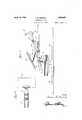
claimed, and illustrated inthe accompanying drawings, in which drawings 65 Figure l is a fragmentary top plan view illustrating my improved device.
Fig. 2 is a fragmentary side elevation of my improved device, illustrating the connec- .1 tion between the brake pedal and the foot 7o board of a motor vehicle, the foot board being shown in section.
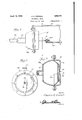
Fig. 3 is a detail` central yertical section through the master control device or'dial. phragm, showing the same in its normal in- 75 operative position.
Fig. 4 is a detail sectional view illustrating the means of connecting the main suc.- tion pipe for themastercontrol device with f, the intake manifold of the internal combustion engine.
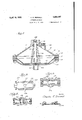
4Fig.,5 is a detail side elevation of one of the brake shoe operating diaphragms.
Fig.. 6 is a vertical section taken on th line 6 6 of Fig. 5. Fig. 7 is a central vertical section thru one of the brake operating diaphragms. Fig. 8 is a'detail sectional view through the three-way valve employed for controlling m the 4operation of the master control dia- '90 phragm device. l. Fig. 9 is a detail longitudinal section thru said valve in the position whereby communication between the master control device and the engine manifoldis established.
Figure 10 isl a fragmentary detail view in longitudinal section showing the joints connecting the two sections of the foot pedal arm.
Figure 11 s a detail longitudinal sectional i view through the three-way valve showing same in position for venting the master control device or diaphragm to atmosphere.
Referring to the drawings in detail, wherein similar reference characters designate corresponding parts throughout the several views, the letter A generally indicates my improved vacuum brake, which comprises a main control device'or diaphragm 10. The main control device or diaphragm 10 embodies a casing 11 including upper and lower companion casing sections 12 and 13 having formed at their peripheries attaching flanges 15. These flanges 15 receive therebetween the flexible' body or diaphragm proper 16. I preferably place the diaphragm proper 16, between spacing rings 17 and sealin washers 18 can be interposed between said rings and the flanges 15.
The lower end of t-hel rod 21 is connected in any desired way, as at 23 at the axial center of the diaphragm proper 16. At one side of the boss 20 the section 12 of the casing 11 is provided with an internally threaded nipple 24, having connected therewith a suction pipe 25. An expansion spring 26 is placed about the diaphragm rod 21 and engages the diaphragm 16 and the inner surface of the section 12 of the casing, and normally functions to hold the diaphragm in its lowered, or inoperative position. An outlet suction nipple 27 is formed on the section 13 of the casing 11 below the diaphragm 16.
Connected with the nipple 27 is a suitable four-way coupling 28 having connected therewith branch pipes 29, 30, 31, and 32 each of which leads to a diaphragm device 34. The auxiliary diaphragm devices 34 each include a sectional casing 35 having clamped between the sections thereof the llexibledi- |aphragm proper 36. I have 'shown one section of each casing 35 provided with a nipple 37 on one side of the diaphragm for conne'ction with its respective suction pipe leading from the coupling 28.
The opposite section of each casing 35 is provided with an axial opening 38 through which extends a rod 39 connected as at 40 with the axial center of the diaphragm. I
provide one of the diaphragm devices 34 for the brake shoes of each Wheel of the vehicle. n
The rods 39 are operatively connected to the brake shoes of the vehicle in any .preferred way. By referring to Fig, 5 of the drawings, it can be seen that I provide a supporting bracket 41 which can beliolted to the casing 35 of each diaphragm device 34, and this bracket is connected to the rod 39 by a contractile coil spring 42, which functions to normally hold the diaphragm in the position shown in Fig. 7 and the brakes in their released position.
It is to be also noted that I have provided an adjustable connection 42 between the spring 42 and the rod 39 so that the tension of this spring can be controlled. It is to be further noted that the opening 38 is of larger diameter than the rod 39 :so that one side of the diaphragm will be subjected to atmospheric pressure at all times.
Referring again to the master control device or diaphragm 10, it isv to be noted that the upper end of the diaphragm rod 21 thereof is pivotally connected as at 43 with the lower end of the brake pedal 44. This brake pedal 44 is rockably mounted at a point Within and intermediate its ends on a suitable bracket 45 which can be secured to the casing 11 of the master control device 10 or to any suitable part of the vehicle. The device 10 is to be secured on the chassis of the vehicle in any desired manner.
The brake pedal extends below the floor boards 46 of the vehicle in the usual way, and is provided with a foot piece 47 to facilitate the operation thereof. From the construction so far, it can be seenthat when the brake pedal is depressed that the rod 21 will be drawn upwardly.
For a purpose, which will presently appear it is to be noted that I have'formed the brake pedal in sections and connect the sections together by a rule or half hinge joint 48 to allow the outer foot pedal section to swing upward independently of the inner section, but which causes the synchronous Swingin of thelpledal sections upon the depressing o the pe a v The outer pedal section is connected to the floor board 46 by a retractile coil spring 49 and thus the brake pedal is normally held in a raised position, with the brakes in their released position. The pipe 25 is connected, preferably by a flexible hose 50, with a tap 51 connected with the intake manifold 52 lof the internal combustion engine of the automobile, and the pipe 25 has interposed in the length thereof a. three-way valve 53.
The valve 53 is provided with an atmosphere port 54 and includes a rotatable valve plug 55 having communicating passages-56 and 56. The plug has secured thereto an operating crank' 57 which is, in turn, operatively connected to the brake pedal 44, as at 58, said connection including a sleeve 58 slidable on the pedal 44 and to which the crank 57 is pivotally connected.
Normally, the valve plug is disposed with the passage 56 in a vertical position, as seen in Figure 11 for closing communication between the master controly device 10 and the manifold 52. When the pedal 44 is depressed,
the plug 55 will be rotated to the position shown in Fig. 9 establishing full communication between the upper end of the master control device and the intake manifold, creating a suction on the upper face of the diaphragm proper 16, causing the raising there- In the operation of my improved brake, the working parts of the device are normally disposed as illustrated in Figs. 3- and 7 of the drawin s, and when it is desired to apply the bra e, the pedal 44 is depressed, which will lift up on lthe rod 21 and. move the flexible di7aphragm proper 16 away from the nipp The master control device 10 will be vented to atmosphere during the initial upward movement of the diaphragm 16 as long as the passage 56 is in communication with the port 54 of the valve 53. This initial movement of the diaphragm 16 is usually suiiicient to cause the desired application of the vehicle bra-kes. Raising of the diaphragm proper will cause a suction on the various pipes 29, 30, 32, and 33. This will create a suction within the auxiliary diaphragm devices 34 and the diaphragm 36 will be moved inward therein, thereby causing a pull on the rod 39 for applying the brakes. As 'explained above, this movement of the brake pedal is generally suflicient to apply the brakes to bring the vehicle to a halt, but should it be desired to apply the brakes quicker or With more force, the brake pedal may be pushed farther down, which will move the valve plug 55'to the position shown in Fig. 9 of the drawings,establishing complete communication between the intake manifold and the upper end of the master control device 10. This suction from the force of the diaphragm 16 which will create a greater suction in the various pipes, 29, 30, 31 and 32.
When it is desired to release the brakes, the pressure is released from the brake pedal 44 and the spring 49 will immediately swing the outer section of the brake pedal 44 u Ward, shutting 0H the suction from the inta e manifold and venting the. master control device 10 to atmosphere by rotating the valve core 55 from the position illustrated in Figure 9 to the position illustrated in Figure 11 of the drawing, thus allowing the spring 26 to `return the diaphragm proper 16 to its lowered position. This forces air to the auxiliary diaphragm devices, and allows the springs 42 to operate the rods 29 for releasing the brake. When the diaphragm 16 returns to inoperative position the inner section of the foot p edal 44 is swung on the bracket 45 in longitudinal alinement with the outer section of the foot pedal by the rod 21, the 'outer section sliding in thetsleeve 58 and said sleeve pivoting on the crank 57' to permit this movement of the inner section without actuating the valves 55, the vdevice is thenready simple, yet durable form of vacuum brake which eliminates the necessity of providing brake rigging as well as the use'of a vacuum cylinder and pistons.
Changes in the details may be made without departing from the spirit or the scope of this invention. v
Having thus described my invention, what I claim as new is i- .v
1. A braking mechanism for motor vehicles comprising a casing, a diaphragm operatively mounted in the casing a suction pipe connecting the casing with the intake manifold of the vehicle engine for actuating the diaphragm, a multiway valve interposed in the pipe for selectively establishing communication between the casing and the manifold and between the casing and the atmosphere for venting the casing a rod fixed to the diaphragm and extending slidably through the casing, a foot pedal pivotally supported intermediate its ends on the casing and having one end pivotally connected to the rod for sto manually actuating the diaphragm, a crank arm having one end fixed to the valve and its other end pivotally and slidably connected to the foot pedal for operating the valve upon actuation of the foot pedal, and brake operating means operatively connected to the casing for actuation by the diaphragm.
2. A braking mechanism for motor vehicles comprising a casing, a diaphragm operatively mounted in the casing,a suction pipe connecting the casing with the intake manifold of the vehicle engine for actuating the diaphragm, a multiway valve interposed in the suction pipe for selectively establishing communication between the casing and the manifold and between the casing and the atmosphere for venting the casing, a sectional foot pedal, one of the sections of the foot pedal being pivotally mounted intermediate its ends on the casing, a rod fixed, at one end, to the diaphragm and extending slidably through the casing and having its other end pivotally connected to one end of the pivotally mounted pedal section for manualactuation by the foot pedal, a half-hinge pivotally connectingthe other section of the foot pedal to the other end of the pivotally mounted section for swinging movement in one direc- 3. A braking mechanism for motor vehicles comprising a casing, a diaphragm operatively mounted in the casing, a suction pipe connecting the casing with the intake manifold of the vehicle engine for pneumatically actuating the diaphragm in one direction, a multiway valve interposed in the suction pipe for selectively establishing communication between the casing and the manifold and between the casingvand the atmosphere for venting the casing, a foot pedal, said foot pedal comprising a pair of sections, means connected with an intermediate portion of one of the sections for pivotally mounting same in the casing, a half hinge pivotally connecting the other section to one end portion of said one section for swinging movement in one direction independently of said one section, a rod extending slidably into the casing and having one end secured to the diaphragm and its other end pivotally connected to the one section for manually actuating the diaphragm in the aforesaid one direction, a coiled spring encircling the rod and engaged with the diaphragm for yiel-dingly urging same in the other direction, a sleeve slidably mounted on the independently swingable pedal section, a crankv arm pivotally connected at one end to the sleeve and at its other endl operatively connected to the valve for actuating said valve, a spring connected to the independently swingable pedal section for actuating same in one direction independently of the first named section, and brake operating means operatively connected to the casing for actuation by the diaphragm.
In testimony whereof I aflix my signature.
CHARLES E. PIERSALL.
Priority Applications (1)
| Application Number | Priority Date | Filing Date | Title |
|---|---|---|---|
| US378135A US1855067A (en) | 1929-07-13 | 1929-07-13 | Automobile brake |
Applications Claiming Priority (1)
| Application Number | Priority Date | Filing Date | Title |
|---|---|---|---|
| US378135A US1855067A (en) | 1929-07-13 | 1929-07-13 | Automobile brake |
Publications (1)
| Publication Number | Publication Date |
|---|---|
| US1855067A true US1855067A (en) | 1932-04-19 |
Family
ID=23491870
Family Applications (1)
| Application Number | Title | Priority Date | Filing Date |
|---|---|---|---|
| US378135A Expired - Lifetime US1855067A (en) | 1929-07-13 | 1929-07-13 | Automobile brake |
Country Status (1)
| Country | Link |
|---|---|
| US (1) | US1855067A (en) |
-
1929
- 1929-07-13 US US378135A patent/US1855067A/en not_active Expired - Lifetime
Similar Documents
| Publication | Publication Date | Title |
|---|---|---|
| US2152084A (en) | Brake | |
| US1588659A (en) | Vehicle brake-control valve | |
| US1855067A (en) | Automobile brake | |
| US1997807A (en) | Vehicle brake | |
| US2643746A (en) | Vacuum operated brake actuator | |
| US2587403A (en) | Fluid pressure operated motor | |
| US2062931A (en) | Retractable auxiliary wheel | |
| US2191987A (en) | Brake | |
| US2318798A (en) | Fluid pressure actuated brake system | |
| US1845995A (en) | Brake actuating mechanism | |
| US2654391A (en) | Servomotor control valve | |
| US2325771A (en) | Throttle brake control mechanism | |
| US2089173A (en) | Power brake means for automotive vehicles | |
| US1879365A (en) | Vacuum brake | |
| GB267478A (en) | Improvements in power actuators or servo-motors | |
| US1665306A (en) | kennington | |
| US2562704A (en) | Fluid control for motor vehicles | |
| US2161279A (en) | Fluid pressure system | |
| US1809491A (en) | Vacuum brake | |
| US2219062A (en) | Power operated brake | |
| US1972330A (en) | Air controlled brake | |
| US1868725A (en) | Brake system for automotive vehicles | |
| US1904267A (en) | Brake system for automotive vehicles | |
| US2057704A (en) | Brake | |
| US1928566A (en) | Power braking and clutch releasing mechanism for automotive vehicles |