US1852287A - Brake mechanism - Google Patents
Brake mechanism Download PDFInfo
- Publication number
- US1852287A US1852287A US374502A US37450229A US1852287A US 1852287 A US1852287 A US 1852287A US 374502 A US374502 A US 374502A US 37450229 A US37450229 A US 37450229A US 1852287 A US1852287 A US 1852287A
- Authority
- US
- United States
- Prior art keywords
- brake
- brake mechanism
- operator
- operated part
- power
- Prior art date
- Legal status (The legal status is an assumption and is not a legal conclusion. Google has not performed a legal analysis and makes no representation as to the accuracy of the status listed.)
- Expired - Lifetime
Links
- 230000007246 mechanism Effects 0.000 title description 117
- ZPUCINDJVBIVPJ-LJISPDSOSA-N cocaine Chemical compound O([C@H]1C[C@@H]2CC[C@@H](N2C)[C@H]1C(=O)OC)C(=O)C1=CC=CC=C1 ZPUCINDJVBIVPJ-LJISPDSOSA-N 0.000 description 4
- 241001421757 Arcas Species 0.000 description 1
- 201000003639 autosomal recessive cerebellar ataxia Diseases 0.000 description 1
- 238000002485 combustion reaction Methods 0.000 description 1
- 230000000295 complement effect Effects 0.000 description 1
- 230000006835 compression Effects 0.000 description 1
- 238000007906 compression Methods 0.000 description 1
- 238000010276 construction Methods 0.000 description 1
- 230000003247 decreasing effect Effects 0.000 description 1
- 239000012530 fluid Substances 0.000 description 1
- 230000002459 sustained effect Effects 0.000 description 1
Images
Classifications
-
- B—PERFORMING OPERATIONS; TRANSPORTING
- B60—VEHICLES IN GENERAL
- B60T—VEHICLE BRAKE CONTROL SYSTEMS OR PARTS THEREOF; BRAKE CONTROL SYSTEMS OR PARTS THEREOF, IN GENERAL; ARRANGEMENT OF BRAKING ELEMENTS ON VEHICLES IN GENERAL; PORTABLE DEVICES FOR PREVENTING UNWANTED MOVEMENT OF VEHICLES; VEHICLE MODIFICATIONS TO FACILITATE COOLING OF BRAKES
- B60T13/00—Transmitting braking action from initiating means to ultimate brake actuator with power assistance or drive; Brake systems incorporating such transmitting means, e.g. air-pressure brake systems
- B60T13/10—Transmitting braking action from initiating means to ultimate brake actuator with power assistance or drive; Brake systems incorporating such transmitting means, e.g. air-pressure brake systems with fluid assistance, drive, or release
Definitions
- rllhis invention relates to brakes and is illustrated as embodied in a brake system for an automotive vehicle. I
- Automotive vehicles of Vthe heavier type such as trucks and busses are usually equipped with two separately operable sets of brake mechanisms, one of' larger areas, which is usually applied by a long hand lever, and the other ot smaller areas, capable of lesser sustained braking eti'ort and usually applied by a toot pedal or toot lever.
- rllhe power which an operator ot a vehicle is capable of by his physical strength and by the leverages through which the torce he is capable of eX- ei-'ting may act.
- the throw of the foot pedal is limited by the distance the operator may conveniently litt his leg, and this in turn is governed by the position of the steering Wheel, which must be located where it can be most etlectively manipulated.
- the foot pedal is usually connected to the brake mechanism of smaller areas which can be effectively applied by the physicalpower ot the operator, but is et insucientarea to meet the maximum braking demands.
- the brake mechanism of smaller areas which can be effectively applied by the physicalpower ot the operator, but is et insucientarea to meet the maximum braking demands.
- larger and more rugged brake mec anism must be used and is usuali connected to the hand lever which provides greater leverage than the foot pedal so that an operator may effectively apply the larger brake mechanism by his physical power,
- lt is still a further object to connect the various elements making up two brake mechanisms so that in case of failure of the power actuator for any reason whatsoever, either brake mechanism may be operated independs ently of the other by physical torce applied to the operator operated part connected thereto.
- loth brake mechanisms may operate on the wheels of the vehicle or one may operate on the wheelsv and the other, usually the foot operated brake, on the propeller shaft (on a shaft driven vehicle) as disclosed.
- the design of the complementary friction elements ot' the brake mechanisms form no part of this invention, they may be of any of the types known to the art, such as external contracting brakes as disclosed.
- he invention described in this application does not lie in the particular power actuator or control mechanism therefor. but rather in the combination of elements described herein which go to make up the brake system as a whole. Therefore ⁇ it. is contemplated to include within the scope of this invention any of the servo motors or power actuators now known to the art such as vacuum servo m0- tors which use a source of low pressure such Sill as the intake manifold as indicated in the embodiment disclosed.
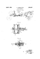
- Fig. 1 is a diagrammatic perspective view of an automotive vehicle showing the arran ement of the various parts of the brake com ination.
- Fig. 2 is a sectional View of a power actuator shown in Fig. 1.
- Fig. 3 is a sectional view of the control valve for the power actuator.
- Z-Z represents brake mechanism for an automotive vehicle which may be' of any type known to the art but which is shown as an external contracting type of brak-e adapted to be actuated bv brake band lever, 1--1 attached to rod, 2-2, connected to brake arm, 3 3, carried by cross shaft, 4, to which is attached power actuator, A, (shown in detail in Fig. 2) by means of rod, 5, connected to the piston rod thereof and arm, 0, which is keyed to shaft, 4.
- the retracting springs are shown at 41 for releasing the brakes.
- the control valve for actuator. A is shown at V, and in detail in Fig. 3.
- llt comprises relatively movable parts which are described in detail hereafter.
- One of said parts, including the valves, is connected to and movable with the bralre mechanism by means of rod, 7, and an arm, 8, which is keyed to cross shaft, 4, as is arm, 6.
- the casing of valve, V, and the other parts connected to and movable with the casing as distinguished from the parts connected to the brake mechanism, are connected to an operator operated part shown as a hand lever, by means of rod, 9.
- Rod, 9, has a slotted yoke, 10, on lthe forward end thereof which 13o-operates with a pin. 11, on the end of the hand lever to form a lost motion connection of that conventional type well-known as a slot and pin connection.
- This lost motion connection allows forward movement of rod, 9, to apply the brake mechanism, Z, under the power of the actuator, A, without movement of the hand lever, 12.
- a vacuum actuator which operates on atmospheric pressure as the higherpressure and a sub-atmospheric pressure as the lowerpressure.
- the lower pressure may be conveniently obtained by connecting the actuator to the intake manifold of the internal combustion engine between the throttle valve and the engine cylinders, pipe, 17, leads from the forward end of the actuator, A, to the intake manifold, 18, and pipe, 127, from the rear thereof through control -valve mechanism to pipe, 17.
- a check Valve, 19, is placed in the line to insure the flow of fluid in one direction only so that if the pressure in the intake manifold should increase over that maintained in the actuator cylinder, the check valve, 19, will close and maintain the lower pressure in the actuator cylinder.
- a separately operable brake mechanism is shown at X, mounted on the propeller shaft, 25, of the vehicle in a lmanner well-lmown to the art.
- Brakev mechanism, X is connected 'to and adapted to be operated by foot pedal, 26, by means of brake arm, 27, and connecting rod, 28.
- a retracting spring attached to pedal, 26, and to a stationary part of the vehicle for returning the brake mechanism, X, to its retracted or off position.
- An intersecting arm, 30, is rigidly secured to rod, 28, and projects in the direction of rod, 9, and has an aperture near one end thereof through which rod, 9, may freely move.
- a collar, 31, is secured to rod, 9, and is spaced from arm, 30, by a coil spring, 32, which is interposed on the rod, 9, between arm, 30, and collar, 31, and is so sized and calibrated that when both brake mechanisms are in retracted position, it will not exert any pressure therebetween.
- the actuator and control valve mechanism are fully described and claimed in other applications liled by us so that we shall only briefly describe them here.
- the actuator, A as shown in this instance (see Fig. 2), comprises a cylinder, 101, closed at both ends by heads, 102, provided with a. piston, 103, having a hollow piston rod, 105, provided with a cap, 108, carrying attaching lug, 109, connected in this instance by a link, 5, to cross shaft, 4f, and thus to brake mechanism, Z-Z.
- r1 ⁇ he cylinder, 101 is shown provided with a guiding sleeve, 1053, secured to one of the heads, 102, and having a guiding engagement with the interior of the hollow piston rod, but
- rlhe valve mechanism, V shown in Fig. 1 and illustrated in detail in Fig. 3, comprises a valve casing, 110, provided with a valve chamber, 111, in which are Alocated a suction valve, 140, and an air inlet valve, 141, slid- 'ingly mounted on a rod, 120, between collars,
- valve casing is provided with a suction chamber, 107, adjacent to the suction valve, having a communicating aperture, 112, and the valve casing is further provided with an air inlet chamber, 113, having an air inlet aperture,
- valve casing, 110 which may communicate with an air strainer as shown.
- Means are provided for limiting the lost motion between the valve casing, 110, and the valve actuating rod, 7, comprising in this instance a collar, 128, on the rod, 7, which is adapted to engage one end ot' an adjustable sleeve, 129, with which the valve casing is provided.
- This lost motion is sucient to permit of the operation of the valve mechanism, and when taken up will transmit the physical force of the operator directly through the valve mechanism to the brake mechanism connected therewith, as herein described.
- the valve chamber, 111, ot the casing is provided with an aperture, 115, which is connected by a pipe, 127, with the cylinder, 101, of the actuator, A, in rear of the piston thereof.
- Suction chamber, 107 oit the valve casing is connected by a pipe, 40, with the pipe, 17, and thus to the intake manifold.
- a spring, 130 between collar, 128, and sleeve, 129, serves to close valve, 141, and open valve, 140, (Fig. 3) whenever the operator operated parts are released or in the released position.
- This spring is so calibrated that it exerts suflicient force to overcome the friction of the various parts of the brake linkage and the action of spring, 150. l
- Spring, 32 is stronger than spring, 130, and when movement of arm, 30, is communicated therethrough to brake rod, 9, spring, 32, overcomes spring, 130, without any appreciable compression of the former.
- Valve mechanism, V maintains the4 rear end of cylinder, 101, connected to the source of vacuum when the actuator is in its released or retracted position (Fig. 2) because when in this position, valve, 140, is unseated, allowing communication between pipes, and 127.
- cylinder, 101 The front end of cylinder, 101, is always in communication with the source of suction through pipe, 17. So, we have what is known as a submerged in vacuum type of actuator y arid it is so called because both sides of the piston are connected to the source of low pressure when the actuator is in released or retracted position.
- low pressure valve, 140 Upon movement of rod, 9, and valve casing, 111, to the left (Fig. 3), low pressure valve, 140, is closed and thereafter high pressure valve, 141, is opened, allowing atmospheric pressure to pass through pipe, 127, to the rear end of cylinder, 101, creating a difference of pressure on both sides of piston. 103, which will cause it to move to the lett (Fig. 2) with resultant application of the liralre mechanism.
- the physical power of the operator may be added thereto by applyingV further pressure to the brake lever, 12, which will cause the lost motion'in valve, V, to be taken up and collar, 120, to contact with adjustable sleeve, 129, so that the physical force of the operator is added and directlycommunicated to the brake mechanism, Z-.Z.
- the operator can Vapply the brake mechanism, Z, by pushing on the foot pedal and compressing spring, 32, which is not sufliciently strong to detract materially trom his physical strength, and he may also apply brake mechanism, Z-Z, by physical force through hand lever, 12, and
- a brake mechanism In combination, a brake mechanism, a power actuator connected to and adapted to apply the said brake mechanism, a, control valve for said power actuator, an operator operated part connected to said control valve, a separate manually operable brake mechanism, ⁇ an operator operated part connected to and adapted to actuate said latter brake.
- a brake mechanism a power actuator connected to and adapted to apply the said brake mechanism, a control va ve for said power actuator, an operator operated part connected tosaid control valve, a separateA manually operable brake mechanism, an operator operated part connected to and adapted to actuate said latter brake mechanism, and yielding means for connecting said latter operator operated part to said control valve so that movement of said latter operator operated part to apply said latter brake mechanism is communicated to said control valve to actuate it and cause said power actuator to apply the brake mechanism connected thereto.
- a brake mecha.- nism adapted to be operated by a power actuator under the control of an operator operated control valve connected thereto, a second brake mechanism, a second operator operated part connected to said second brake mechanism to operate the same, and means for connectingr said second operator operated part to said control valve so that movement of the second operator operated part to apply the brake mechanism connected thereto will actuate said control valve and cause said power actuator to apply the first mentioned brake mechanism.
- a plurality of brake mechanisms some of said brake mechanisms adapted to be actuated by a power actuator under the control of an operator operated control valve connected thereto, a second operator operated part connected to other of said brake mechanisms to operate the latter by physical power applied to said second operated part and means for communicating movement of the latter operator operated part to the control valve to cause relative movement ot the parts thereof and resultant actuation of the power actuator to apply the first mentioned brake mechanism.
- a brake system comprising a brake mechanism, a power actuator connected to and adapted to actuate said brake mechanism, and a control valve for said power actuator'and a separately operable brake system comprising brake mechanism, an operator operated part, linkage connecting said operator operated part and said latter brake mechanism to enable the operator to apply said latter brake mechanism by physical power; and yielding means connecting said brake. systems and capable of transmitting only enough force to actuate said control valve'but not enough to apply said first mentioned brake mechanism without the aid of said power actuator when the operator applies his physical force to-said latter operator operated part.
- a brake system for an automotive vehicle brake mechanism adapted to be operated by power, a power actuator operab'ly connected thereto, an operator operated part for said brake mechanism adapted to control said brake mechanism when loperated by power, and to enable the operator to actuate said brake mechanism by physical force in case of failure ofv power, a control valve for said poweractuator connected to said operator operated part and to said brake mechanism and adapted to be actuated'by said operator operated part and said brake mechanism, a separate brake mechanism, a second operator operated part connected to said separate brake mechanism to operate the same and means for connecting said latter operator operated part to said control valve so that movement of said latter operator operated part will cause the actuation of said control valve to operate said power actuator but will not produce an application of the first mentioned brake mechanism by physical force exerted on the last mentioned operator operated part.
- a power brake mechanism comprising complemental friction elements, a power actuator operably connected thereto, a control valve for said power actuator, an operator operated part, and brake linkage connecting said operator operated part, said control valve and the movable element of said power actuator, physically operable brake mechanism, a second operator operated part, and brake linkage operably connecting said brake mechanism and said second mentioned operator operated part, and means for yieldably connecting the respective brake linkages so that movement of the latter will produce actuation of said control valve with resultant application of the first mentioned brake mechanism by said power actuator.
- a power operated brake system comprising, brake mechanism, a power actuator comprising stationary and movable parts, said actuator adapted to actuate said brake mechanism, a
- control valve for said power actuator having relatively movable parts operated by a lostl motion connection, an operator operated part forsaid power operated brake system, brake linkage connecting said operator operated part to one part of said valve mechanism and the other part of Vsaid valve lmechanism to said brake mechanism and to the movable element of said power actuator, a manually operable brake system comprising brake mechanism, an operator operated part for said manually operable brake system, brake linkage connecting said second operator operated part to said second mentioned brake mechanism, an arm rigidly attached to the manually operable brake linkage with means for slidably receiving said power operated brake linkage, and a spring interposed between said arm and a collar attached to said llast mentioned brake linkage so that movement of said physically operable brake linkage to apply the brake mechanism connected thereto will cause sutlicient motion of said first mentioned linkage to actua-te-said control valve with resultant movement of said power actuator to apply said first mentioned brake mechanism but will not cause sufficient motion to apply said power brake mechanism by the physical force applied to the last mentioned operator operated part.
- a power operated brake system comprisingan operator operated part, brake mechanism, a power actuator adapted to actuate said mechanism, a control valve for said power actuator, linkage connect-ing the relatively movable parts of said control valve with said brake mechanism and said operator operatedpart respectively, a manually operable brake mechanism, an operator operated part therefor, linkage connecting this latter operator operated part' with said manually operable brake mechanism, and means for connecting the respective brake' linkages together through a yielding connection in order that movement of the manually operable brake linkage is communicated to the power operated brake linkage with sufficient force to cause relative movement between the parts of the control valve but not to cause physical operation of the power operated brake system by force applied'to the operator operated part of the .manually operable brake system in case of failure of the power actuator to respond to the actuation of the control valve.
- a brake mechanism adapted to be applied by power, a power actuator connected thereto, a control valve for said power actuator, an operator operated part for said brake mechanism, linkage connecting said operator operated part to said control valve and to said brake mechanism, a brake mechanism adapted to be operated by the physical power of the operator, an operator .operated part for said latter brake mechanism, linkage connecting said latter operator operated part to said latter 'brake mechanism, and means for yieldably connecting said latter linkage to said former linkage between the operator operated part therefor and the control valve so that movement of the latter linkage may be communicated to said control valve to cause actuation of said servo motor.
- a power operat-ed brake syst-em comprising brake mechanism, a power actuator operably connected thereto, a control valve for said power actuator, an operator operated part for said brake mechanism, linkage connecting said operator operated part, said control valve and said brake mechanism, a lost motion connection between said linkage and said operator operated part so that said linkage may be moved to apply the brake mechanism
- a separate physically operable brake system comprising, brake mechanism, a separate operator operated part therefor, linkage connecting said latter operator operated part to said latter brake mechanism, and means for connecting said brake systems so that operation of the latter by physical force will cause operation of the former by the power actuator.
- a ower operated brake system comprising bra (e mechanism, al power actuator operably connected thereto, a control valve for said power actuator, an operator operated part for said brake mechanism, linkage connecting said operator operated part, said control valve and said brake mechanism, a lost motionconnection between said linkage and said operator operated part so that said linkage may be moved to apply the brake mechanism without moving said operator operated part, a separate physically operable brake system lcomprising brake mechanism, a separate operatoroperated part therefor, linkage connecting said latter operator operated part to said latter brake mechanism, and yielding means connecting said brake systems so that operation of the latter by physicalforce will cause operation of the former by power supplied by' the p ower actuator but will not cause operation thereof by physical force applied to said latter operator operated part in case of failure of said power actuator.
Landscapes
- Engineering & Computer Science (AREA)
- Transportation (AREA)
- Mechanical Engineering (AREA)
- Braking Systems And Boosters (AREA)
Description
c. s. BRAGG E1' AL BRAKE MECHANISM- April 5, 1932.
Filed June 28, 1929 [O2 /02 l 'oa /cL y IOS ll IH I7 [27 INVENTORS ATTO EY l exerting on the brake mechanism is limited titl Patented Apr. 5, 1932 UNITED STATES PATENT OFFICE UALEB S. BRAGG, OF PALM BEACH, LORIDA, AND VICTOR W. KLIESRATI-I, F PORT WASHINGTON, NEW YORK, ASSIGNORS LONG ISLAND CITY, NEW YORK TO BRAGG-KLIESRATII CORPORATIOIHOF BRAKE MECHAN ISM Application filed June 28,
rllhis invention relates to brakes and is illustrated as embodied in a brake system for an automotive vehicle. I
Automotive vehicles of Vthe heavier type such as trucks and busses are usually equipped with two separately operable sets of brake mechanisms, one of' larger areas, which is usually applied by a long hand lever, and the other ot smaller areas, capable of lesser sustained braking eti'ort and usually applied by a toot pedal or toot lever. rllhe power which an operator ot a vehicle is capable of by his physical strength and by the leverages through which the torce he is capable of eX- ei-'ting may act. The throw of the foot pedal is limited by the distance the operator may conveniently litt his leg, and this in turn is governed by the position of the steering Wheel, which must be located where it can be most etlectively manipulated. As a result ot these limitations, the foot pedal is usually connected to the brake mechanism of smaller areas which can be effectively applied by the physicalpower ot the operator, but is et insucientarea to meet the maximum braking demands. For severe or continued braking ettort such as is necessary when the vehicle is travelling at high speed or descending steep rades, larger and more rugged brake mec anism must be used and is usuali connected to the hand lever which provides greater leverage than the foot pedal so that an operator may effectively apply the larger brake mechanism by his physical power,
lltith extreme weights and speeds it is desirable and almost necessary to use the brake mechanism having the larger braking arcas or to use both brake mechanisms simultaneously to obtain the desired deceleration Without burning out the triction elements ot the brakes, but it is often inconvenient and perhaps even dangerous or impossible tor an operator to remove his hand from the steering wheel and to operate the hand lever while pressing on the toot pedal, whereas he can always operate the "toot pedal alone, so it is an object ot this invention to produce a combination ot' elements which will enable the 1929. Serial N0. 374,502.
operator to apply both brake mechanisms simultaneously upon actuation of one of the operator operated parts, in this case the Vfoot pedal.
Itis also an object of this invention to utilize simultaneously all the brake areas available on an automotive vehicle with practically no more physical effort than is required to actuate only 'part of the brake equfpment and to accomplish this by the movement ot' only one operator operated part and at the same time to make each brake systcm with its separate operator operated part independently operable by`- physical power, and 'to do all these with a minimum ot parts.
lt is still a further object to connect the various elements making up two brake mechanisms so that in case of failure of the power actuator for any reason whatsoever, either brake mechanism may be operated independs ently of the other by physical torce applied to the operator operated part connected thereto.
1We accomplish these objects by using a servo motor or power actuator to operate one brake mechanism, usually the larger brake mechanism, and furnish a control mechanism for said power actuator, capable oi' being actuated bv either the hand operated brake lever or the foot pedal.
loth brake mechanisms may operate on the wheels of the vehicle or one may operate on the wheelsv and the other, usually the foot operated brake, on the propeller shaft (on a shaft driven vehicle) as disclosed. As the design of the complementary friction elements ot' the brake mechanisms form no part of this invention, they may be of any of the types known to the art, such as external contracting brakes as disclosed.
'l` he invention described in this application does not lie in the particular power actuator or control mechanism therefor. but rather in the combination of elements described herein which go to make up the brake system as a whole. Therefore` it. is contemplated to include within the scope of this invention any of the servo motors or power actuators now known to the art such as vacuum servo m0- tors which use a source of low pressure such Sill as the intake manifold as indicated in the embodiment disclosed.
The above and other objects and features of the invention, including various novel combinations of parts and desirable particular constructions, will be apparent from the following description of one illustrative embodiment shown in the accompanying drawings in which,
Fig. 1 is a diagrammatic perspective view of an automotive vehicle showing the arran ement of the various parts of the brake com ination.
Fig. 2 is a sectional View of a power actuator shown in Fig. 1.
Fig. 3 is a sectional view of the control valve for the power actuator.
In the embodiment of our invention shown in Fig. 1, Z-Z represents brake mechanism for an automotive vehicle which may be' of any type known to the art but which is shown as an external contracting type of brak-e adapted to be actuated bv brake band lever, 1--1 attached to rod, 2-2, connected to brake arm, 3 3, carried by cross shaft, 4, to which is attached power actuator, A, (shown in detail in Fig. 2) by means of rod, 5, connected to the piston rod thereof and arm, 0, which is keyed to shaft, 4. The retracting springs are shown at 41 for releasing the brakes.
The control valve for actuator. A, is shown at V, and in detail in Fig. 3. llt comprises relatively movable parts which are described in detail hereafter. One of said parts, including the valves, is connected to and movable with the bralre mechanism by means of rod, 7, and an arm, 8, which is keyed to cross shaft, 4, as is arm, 6. The casing of valve, V, and the other parts connected to and movable with the casing as distinguished from the parts connected to the brake mechanism, are connected to an operator operated part shown as a hand lever, by means of rod, 9.
Rod, 9, has a slotted yoke, 10, on lthe forward end thereof which 13o-operates with a pin. 11, on the end of the hand lever to form a lost motion connection of that conventional type well-known as a slot and pin connection. This lost motion connection allows forward movement of rod, 9, to apply the brake mechanism, Z, under the power of the actuator, A, without movement of the hand lever, 12. which is of the usual emergency brake type pivoted at 13, and having a locking ratchet and pawl, 14, operated by the auxiliary hand lever,l 15.
We have seen it to describe our invention as embodying that type of power actuator known as a. vacuum actuator which operates on atmospheric pressure as the higherpressure and a sub-atmospheric pressure as the lowerpressure. The lower pressure may be conveniently obtained by connecting the actuator to the intake manifold of the internal combustion engine between the throttle valve and the engine cylinders, pipe, 17, leads from the forward end of the actuator, A, to the intake manifold, 18, and pipe, 127, from the rear thereof through control -valve mechanism to pipe, 17. A check Valve, 19, is placed in the line to insure the flow of fluid in one direction only so that if the pressure in the intake manifold should increase over that maintained in the actuator cylinder, the check valve, 19, will close and maintain the lower pressure in the actuator cylinder.
A separately operable brake mechanism is shown at X, mounted on the propeller shaft, 25, of the vehicle in a lmanner well-lmown to the art. Brakev mechanism, X, is connected 'to and adapted to be operated by foot pedal, 26, by means of brake arm, 27, and connecting rod, 28. At 29 we have shown a retracting spring attached to pedal, 26, and to a stationary part of the vehicle for returning the brake mechanism, X, to its retracted or off position.
An intersecting arm, 30, is rigidly secured to rod, 28, and projects in the direction of rod, 9, and has an aperture near one end thereof through which rod, 9, may freely move. A collar, 31, is secured to rod, 9, and is spaced from arm, 30, by a coil spring, 32, which is interposed on the rod, 9, between arm, 30, and collar, 31, and is so sized and calibrated that when both brake mechanisms are in retracted position, it will not exert any pressure therebetween.
The actuator and control valve mechanism are fully described and claimed in other applications liled by us so that we shall only briefly describe them here. The actuator, A, as shown in this instance (see Fig. 2), comprises a cylinder, 101, closed at both ends by heads, 102, provided with a. piston, 103, having a hollow piston rod, 105, provided with a cap, 108, carrying attaching lug, 109, connected in this instance by a link, 5, to cross shaft, 4f, and thus to brake mechanism, Z-Z. r1`he cylinder, 101, is shown provided with a guiding sleeve, 1053, secured to one of the heads, 102, and having a guiding engagement with the interior of the hollow piston rod, but
this is not essential. rThe forward end of the cylinder, 101, is connected by a pipe, 17, with the intake manifold, as shown in Fig. 1.
rlhe valve mechanism, V, shown in Fig. 1 and illustrated in detail in Fig. 3, comprises a valve casing, 110, provided with a valve chamber, 111, in which are Alocated a suction valve, 140, and an air inlet valve, 141, slid- 'ingly mounted on a rod, 120, between collars,
140a and 14:1, and provided with an intermediate spring, or springs, 150. The valve casing is provided with a suction chamber, 107, adjacent to the suction valve, having a communicating aperture, 112, and the valve casing is further provided with an air inlet chamber, 113, having an air inlet aperture,
llt
114, which may communicate with an air strainer as shown. Means are provided for limiting the lost motion between the valve casing, 110, and the valve actuating rod, 7, comprising in this instance a collar, 128, on the rod, 7, which is adapted to engage one end ot' an adjustable sleeve, 129, with which the valve casing is provided. This lost motion is sucient to permit of the operation of the valve mechanism, and when taken up will transmit the physical force of the operator directly through the valve mechanism to the brake mechanism connected therewith, as herein described. The valve chamber, 111, ot the casing is provided with an aperture, 115, which is connected by a pipe, 127, with the cylinder, 101, of the actuator, A, in rear of the piston thereof. Suction chamber, 107, oit the valve casing is connected by a pipe, 40, with the pipe, 17, and thus to the intake manifold. A spring, 130, between collar, 128, and sleeve, 129, serves to close valve, 141, and open valve, 140, (Fig. 3) whenever the operator operated parts are released or in the released position. This spring is so calibrated that it exerts suflicient force to overcome the friction of the various parts of the brake linkage and the action of spring, 150. l
Spring, 32, is stronger than spring, 130, and when movement of arm, 30, is communicated therethrough to brake rod, 9, spring, 32, overcomes spring, 130, without any appreciable compression of the former.
Valve mechanism, V, maintains the4 rear end of cylinder, 101, connected to the source of vacuum when the actuator is in its released or retracted position (Fig. 2) because when in this position, valve, 140, is unseated, allowing communication between pipes, and 127.
Y The front end of cylinder, 101, is always in communication with the source of suction through pipe, 17. So, we have what is known as a submerged in vacuum type of actuator y arid it is so called because both sides of the piston are connected to the source of low pressure when the actuator is in released or retracted position. Upon movement of rod, 9, and valve casing, 111, to the left (Fig. 3), low pressure valve, 140, is closed and thereafter high pressure valve, 141, is opened, allowing atmospheric pressure to pass through pipe, 127, to the rear end of cylinder, 101, creating a difference of pressure on both sides of piston. 103, which will cause it to move to the lett (Fig. 2) with resultant application of the liralre mechanism. When the operator ceases to moveTod, 9, forwardly or to the left (Fig. 1) and holds it stationary, the power actuator will continue to move rod, 7, to the left until the high pressure inlet valve, 141, closes and the brake system comes to a state of equilibrium with the forces actingr to apply the brakes just equal and opposite to the resistance ot the brake mechanism. Further movement of the rod, 9, tothe left by the operator the pressure on the operator operated part which is serving to actuate rod, -9, andthe result is that spring, 130, closes the high pressure valve, 141, and upon further movement opens low pressure valve, 140, so thatthe rear end of the cylinder is reconnected to the source of low pressure and the differential of pressure acting upon piston, 103, is decreased with4 a resultant decrease of braking effort, and when the pressure is equalized on both sides of the piston, the retracting springs, 41,-41,
will return the brake mechanism to its off position. lVhether rod, 9, is moved by hand lever, 12, or by the foot pedal, the mode of operation described above is obtained. .When the operator presses foot pedal, 26, and actuates brake mechanism, X, arm, 80, will engage spring, 32, which is so calibrated that it will transmit enough force to collar, 31, and rod9, to operate valve, V, before being compressed, so that actuator. A, lwill apply brake mechanism, Z-Z. The brakes will be applied, held as applied or released at the will of the operator as described in the llast paragraph and their application or release will be proportional to the movement of the foot pedal, 26.
After the power actuator, A, has exerted its maximum force in applying the brake mechanism, Z-Z, the physical power of the operator may be added thereto by applyingV further pressure to the brake lever, 12, which will cause the lost motion'in valve, V, to be taken up and collar, 120, to contact with adjustable sleeve, 129, so that the physical force of the operator is added and directlycommunicated to the brake mechanism, Z-.Z.
It may be seen from the above description and explanation of the mode of operation of our device that no more ei'ort is required of the operator to apply both sets of brake mechanisms than is required to operate brake mechanism, X, alone, except for the force required to overcome the spring, 130, in valve mechanism, V. This 1s very small and may be considered as negligible.
Should the power fail, the operator can Vapply the brake mechanism, Z, by pushing on the foot pedal and compressing spring, 32, which is not sufliciently strong to detract materially trom his physical strength, and he may also apply brake mechanism, Z-Z, by physical force through hand lever, 12, and
thus operate either or both brake mechanisms just as if no power actuator were on the vehicle.
lVe claim 1. In combination, a brake mechanism, a power actuator connected to and adapted to apply the said brake mechanism, a, control valve for said power actuator, an operator operated part connected to said control valve, a separate manually operable brake mechanism,` an operator operated part connected to and adapted to actuate said latter brake.
mechanism, and means for connecting said latter operator operated part to said control valve so that movement of said latter operator operated part to apply said latter brake mechanism is communicated to said control valve to actuate it and cause said power actuator to apply the brake mechanism connected thereto.
2. In combination, a brake mechanism, a power actuator connected to and adapted to apply the said brake mechanism, a control va ve for said power actuator, an operator operated part connected tosaid control valve, a separateA manually operable brake mechanism, an operator operated part connected to and adapted to actuate said latter brake mechanism, and yielding means for connecting said latter operator operated part to said control valve so that movement of said latter operator operated part to apply said latter brake mechanism is communicated to said control valve to actuate it and cause said power actuator to apply the brake mechanism connected thereto.
3. In an automotive vehicle, a brake mecha.- nism adapted to be operated by a power actuator under the control of an operator operated control valve connected thereto, a second brake mechanism, a second operator operated part connected to said second brake mechanism to operate the same, and means for connectingr said second operator operated part to said control valve so that movement of the second operator operated part to apply the brake mechanism connected thereto will actuate said control valve and cause said power actuator to apply the first mentioned brake mechanism.
4. In an automotive vehicle, a plurality of brake mechanisms, some of said brake mechanisms adapted to be actuated by a power actuator under the control of an operator operated control valve connected thereto, a second operator operated part connected to other of said brake mechanisms to operate the latter by physical power applied to said second operated part and means for communicating movement of the latter operator operated part to the control valve to cause relative movement ot the parts thereof and resultant actuation of the power actuator to apply the first mentioned brake mechanism.
5. n an automotive vehicle, a brake system comprising a brake mechanism, a power actuator connected to and adapted to actuate said brake mechanism, and a control valve for said power actuator'and a separately operable brake system comprising brake mechanism, an operator operated part, linkage connecting said operator operated part and said latter brake mechanism to enable the operator to apply said latter brake mechanism by physical power; and yielding means connecting said brake. systems and capable of transmitting only enough force to actuate said control valve'but not enough to apply said first mentioned brake mechanism without the aid of said power actuator when the operator applies his physical force to-said latter operator operated part.
6. In a brake system for an automotive vehicle, brake mechanism adapted to be operated by power, a power actuator operab'ly connected thereto, an operator operated part for said brake mechanism adapted to control said brake mechanism when loperated by power, and to enable the operator to actuate said brake mechanism by physical force in case of failure ofv power, a control valve for said poweractuator connected to said operator operated part and to said brake mechanism and adapted to be actuated'by said operator operated part and said brake mechanism, a separate brake mechanism, a second operator operated part connected to said separate brake mechanism to operate the same and means for connecting said latter operator operated part to said control valve so that movement of said latter operator operated part will cause the actuation of said control valve to operate said power actuator but will not produce an application of the first mentioned brake mechanism by physical force exerted on the last mentioned operator operated part.
7. In an automotive brake system, a power brake mechanism comprising complemental friction elements, a power actuator operably connected thereto, a control valve for said power actuator, an operator operated part, and brake linkage connecting said operator operated part, said control valve and the movable element of said power actuator, physically operable brake mechanism, a second operator operated part, and brake linkage operably connecting said brake mechanism and said second mentioned operator operated part, and means for yieldably connecting the respective brake linkages so that movement of the latter will produce actuation of said control valve with resultant application of the first mentioned brake mechanism by said power actuator.
8. In an automotive vehicle, a power operated brake system comprising, brake mechanism, a power actuator comprising stationary and movable parts, said actuator adapted to actuate said brake mechanism, a
` control valve for said power actuator having relatively movable parts operated by a lostl motion connection, an operator operated part forsaid power operated brake system, brake linkage connecting said operator operated part to one part of said valve mechanism and the other part of Vsaid valve lmechanism to said brake mechanism and to the movable element of said power actuator, a manually operable brake system comprising brake mechanism, an operator operated part for said manually operable brake system, brake linkage connecting said second operator operated part to said second mentioned brake mechanism, an arm rigidly attached to the manually operable brake linkage with means for slidably receiving said power operated brake linkage, and a spring interposed between said arm and a collar attached to said llast mentioned brake linkage so that movement of said physically operable brake linkage to apply the brake mechanism connected thereto will cause sutlicient motion of said first mentioned linkage to actua-te-said control valve with resultant movement of said power actuator to apply said first mentioned brake mechanism but will not cause sufficient motion to apply said power brake mechanism by the physical force applied to the last mentioned operator operated part.
9. In an automotive vehicle, a power operated brake system comprisingan operator operated part, brake mechanism, a power actuator adapted to actuate said mechanism, a control valve for said power actuator, linkage connect-ing the relatively movable parts of said control valve with said brake mechanism and said operator operatedpart respectively, a manually operable brake mechanism, an operator operated part therefor, linkage connecting this latter operator operated part' with said manually operable brake mechanism, and means for connecting the respective brake' linkages together through a yielding connection in order that movement of the manually operable brake linkage is communicated to the power operated brake linkage with sufficient force to cause relative movement between the parts of the control valve but not to cause physical operation of the power operated brake system by force applied'to the operator operated part of the .manually operable brake system in case of failure of the power actuator to respond to the actuation of the control valve.
10. In a brake system for an automotive vehicle, a brake mechanism adapted to be applied by power, a power actuator connected thereto, a control valve for said power actuator, an operator operated part for said brake mechanism, linkage connecting said operator operated part to said control valve and to said brake mechanism, a brake mechanism adapted to be operated by the physical power of the operator, an operator .operated part for said latter brake mechanism, linkage connecting said latter operator operated part to said latter 'brake mechanism, and means for yieldably connecting said latter linkage to said former linkage between the operator operated part therefor and the control valve so that movement of the latter linkage may be communicated to said control valve to cause actuation of said servo motor.
11. In an automotive vehicle, a power operat-ed brake syst-em comprising brake mechanism, a power actuator operably connected thereto, a control valve for said power actuator, an operator operated part for said brake mechanism, linkage connecting said operator operated part, said control valve and said brake mechanism, a lost motion connection between said linkage and said operator operated part so that said linkage may be moved to apply the brake mechanism Without moving said operator operated part, a separate physically operable brake system comprising, brake mechanism, a separate operator operated part therefor, linkage connecting said latter operator operated part to said latter brake mechanism, and means for connecting said brake systems so that operation of the latter by physical force will cause operation of the former by the power actuator.
12. In an automotive vehicle, a ower operated brake system comprising bra (e mechanism, al power actuator operably connected thereto, a control valve for said power actuator, an operator operated part for said brake mechanism, linkage connecting said operator operated part, said control valve and said brake mechanism, a lost motionconnection between said linkage and said operator operated part so that said linkage may be moved to apply the brake mechanism without moving said operator operated part, a separate physically operable brake system lcomprising brake mechanism, a separate operatoroperated part therefor, linkage connecting said latter operator operated part to said latter brake mechanism, and yielding means connecting said brake systems so that operation of the latter by physicalforce will cause operation of the former by power supplied by' the p ower actuator but will not cause operation thereof by physical force applied to said latter operator operated part in case of failure of said power actuator.
In testimony whereof we have hereunto set our hands.
CALEB S. BRAGG. l
VICTOR W. KLIESRATI-I.
Priority Applications (1)
| Application Number | Priority Date | Filing Date | Title |
|---|---|---|---|
| US374502A US1852287A (en) | 1929-06-28 | 1929-06-28 | Brake mechanism |
Applications Claiming Priority (1)
| Application Number | Priority Date | Filing Date | Title |
|---|---|---|---|
| US374502A US1852287A (en) | 1929-06-28 | 1929-06-28 | Brake mechanism |
Publications (1)
| Publication Number | Publication Date |
|---|---|
| US1852287A true US1852287A (en) | 1932-04-05 |
Family
ID=23477118
Family Applications (1)
| Application Number | Title | Priority Date | Filing Date |
|---|---|---|---|
| US374502A Expired - Lifetime US1852287A (en) | 1929-06-28 | 1929-06-28 | Brake mechanism |
Country Status (1)
| Country | Link |
|---|---|
| US (1) | US1852287A (en) |
Cited By (4)
| Publication number | Priority date | Publication date | Assignee | Title |
|---|---|---|---|---|
| US2578388A (en) * | 1947-04-08 | 1951-12-11 | Mack Mfg Corp | Brake system for vehicles |
| US2670057A (en) * | 1950-08-15 | 1954-02-23 | Austin Motor Co Ltd | Hydromechanical braking system for road vehicles |
| US3501040A (en) * | 1965-05-19 | 1970-03-17 | Cockerill | Traction vehicle with interchangeable bodies |
| US4706785A (en) * | 1986-07-25 | 1987-11-17 | General Motors Corporation | Single point actuated self-adjusting brake mechanism in a vehicle driven by a cross-drive transmission |
-
1929
- 1929-06-28 US US374502A patent/US1852287A/en not_active Expired - Lifetime
Cited By (4)
| Publication number | Priority date | Publication date | Assignee | Title |
|---|---|---|---|---|
| US2578388A (en) * | 1947-04-08 | 1951-12-11 | Mack Mfg Corp | Brake system for vehicles |
| US2670057A (en) * | 1950-08-15 | 1954-02-23 | Austin Motor Co Ltd | Hydromechanical braking system for road vehicles |
| US3501040A (en) * | 1965-05-19 | 1970-03-17 | Cockerill | Traction vehicle with interchangeable bodies |
| US4706785A (en) * | 1986-07-25 | 1987-11-17 | General Motors Corporation | Single point actuated self-adjusting brake mechanism in a vehicle driven by a cross-drive transmission |
Similar Documents
| Publication | Publication Date | Title |
|---|---|---|
| US2352357A (en) | Pneumatically assisted hydraulic brake system | |
| US1852287A (en) | Brake mechanism | |
| US2041884A (en) | Brake mechanism | |
| US2834184A (en) | Booster brake mechanism | |
| US2404932A (en) | Brake booster | |
| US1565767A (en) | Vacuum brake | |
| US1694020A (en) | Hydraulic and band brake-operating means | |
| US1733936A (en) | Leverage system | |
| US1472801A (en) | Pneumatically-assisted pressure-producing mechanism | |
| US2191987A (en) | Brake | |
| US1844631A (en) | Power actuator | |
| US1883588A (en) | Fluid brake | |
| US1868725A (en) | Brake system for automotive vehicles | |
| US1606045A (en) | Brake mechanism | |
| US1904267A (en) | Brake system for automotive vehicles | |
| US1848458A (en) | And victor w | |
| US2102461A (en) | Brake controlling appliance | |
| US2258907A (en) | Brake | |
| US2566614A (en) | Hydraulic brake | |
| US1822688A (en) | Brake mechanism for automotive vehicles | |
| US2043732A (en) | Brake mechanism for automotive vehicles | |
| GB267478A (en) | Improvements in power actuators or servo-motors | |
| US1723140A (en) | Automotive brake equipment | |
| US2173836A (en) | Vehicle brake mechanism | |
| US1954520A (en) | Brake mechanism |