US1855058A - Sound box guiding mechanism - Google Patents
Sound box guiding mechanism Download PDFInfo
- Publication number
- US1855058A US1855058A US457280A US45728030A US1855058A US 1855058 A US1855058 A US 1855058A US 457280 A US457280 A US 457280A US 45728030 A US45728030 A US 45728030A US 1855058 A US1855058 A US 1855058A
- Authority
- US
- United States
- Prior art keywords
- sound box
- spindle
- casing
- bushing
- sound
- Prior art date
- Legal status (The legal status is an assumption and is not a legal conclusion. Google has not performed a legal analysis and makes no representation as to the accuracy of the status listed.)
- Expired - Lifetime
Links
- 230000008878 coupling Effects 0.000 description 6
- 238000010168 coupling process Methods 0.000 description 6
- 238000005859 coupling reaction Methods 0.000 description 6
- 238000010276 construction Methods 0.000 description 1
- 230000000717 retained effect Effects 0.000 description 1
Images
Classifications
-
- G—PHYSICS
- G11—INFORMATION STORAGE
- G11B—INFORMATION STORAGE BASED ON RELATIVE MOVEMENT BETWEEN RECORD CARRIER AND TRANSDUCER
- G11B3/00—Recording by mechanical cutting, deforming or pressing, e.g. of grooves or pits; Reproducing by mechanical sensing; Record carriers therefor
- G11B3/02—Arrangements of heads
- G11B3/10—Arranging, supporting, or driving of heads or of transducers relatively to record carriers
- G11B3/34—Driving or guiding during transducing operation
- G11B3/36—Automatic-feed mechanisms producing progressive transducing traverse across record carriers otherwise than by grooves, e.g. by lead-screw
Definitions
- the sound'box is actuated by a screw 1 spindle having 'a very fine thread and in order to guide the sound box there are also disposed rods or bars and the like along side of said spindle. All of these parts are supported at both of these ends so as to bring into the construction a large number of bearing points n and the assembly operation is thereby considerably increased.
- the device of the present application is distinguished substantially from the known devices by the fact that the spindle for actuating the sound box is located within a casing.
- This casing is constructed as an element projecting freely over the record car: rier and it serves as a guide way for the sound box.
- Other features of the invention as deal with the cooperation of the body of the sound box with the actuating device.
- Figure l is a front elevation.
- Figure 2 is a top plan view.
- Figure 3 is a-partial section on line 3-3 of Figure 2.
- the box plate a on which the entire device is mounted is provided with aperture forthe 3o passage of the shaft 0 on which the record carrier 6 is secured, the shaft 0 beingactuated by a motor and said motor also driving as for instance by means of a cord the pulley d and the threaded spindle e for the sound box f.
- the record carrier 12 supports that record blank 9 on which the sound reproducing grooves are to be impressed.
- the sound box actuating spindle e is disposed within a cylindrical casin h supported at one end only.
- the other record carrier and it is provided at its top with a cut out portion or slot 70 having the edges 2' and 7'.
- a sleeve or bushin Z is slidably located surrounding the casin This bushingl is longitudinally slid'ab e on the casing r ce end projects over the h having arms m for a pivot pin n on which the sound box 7 is pivotally secured by means of bearing lu s o.
- the sleeve or bushing Z and the sound box 7 carried thereby are in releasable connection with the spindle e through a coupling element.
- This coupling element comprises a double armed lever pivoted on the pin 12.
- One arm p of said lever has a screw thread for engaging the thread of the spindle e, said spindle being accessible for the purpose of this engagement owing to the provision of the cut out portion In, in the casing h and the cut out portion in the bushing Z.
- a spring 7' is provided which rests on a I projection 8 of the arm 1?.
- the other arm t of the coupling member servesas a handle by means of which the arm 39 may be disen-. gaged from the spindle e and may then be automatically retained in disengaged position since the free end of the spring 7 will then enter a notch u on the arm 12.
- the bushing Z is provided with a tubular extension '0 containing a springcontrolled slidable pin w, the inner end of which has a slanting surface w. Upon moving the bushing in a direction to lift the sound box from the record this pin enters the slot is of the cpsing h and then engages the edge i of said s ot.
- I claimv 1 In apparatus for guiding the sound box in the production of records, a threaded revoluble spindle, a tubular casing in which said spindle is arranged, a sound box having a bushing which is mounted concentrically on the casing and for pivotal'movement thereon to permit raising and-lowerin of the sound box, a coupling member carrie by the sound box and engageable with the threaded spins dle, said casin and bushing having openings through whic the threaded spindle is exposed and through which said coupling is.
- e bushing is provided with a stop element to limit its rotary movement about the spindle casing, said stop element engaging in one terminal position an edge 11 of the casing and said stop element being provided with a slanting sui'face me which upon return movement of the bushing slides over the other edge of the casing.
Landscapes
- Casings For Electric Apparatus (AREA)
Description
April 19, 1932.
v s. KATSCHER SOUND BOX GUIDING MECHANISI Filed May 29 I 1930 Patented Apr. 19, 1932 SIGMUND KATSGHER, VIENNA, AUSTRIA SOUND BOX GUIDING MECHANISM application. filed Kay 29, 1930, Serial No. 457,280, and in Austria January 30, 1980.
In the known devices for guiding the sound box when producing a reproduction on a record, the sound'box is actuated by a screw 1 spindle having 'a very fine thread and in order to guide the sound box there are also disposed rods or bars and the like along side of said spindle. All of these parts are supported at both of these ends so as to bring into the construction a large number of bearing points n and the assembly operation is thereby considerably increased.
The device of the present application is distinguished substantially from the known devices by the fact that the spindle for actuating the sound box is located within a casing. This casing is constructed as an element projecting freely over the record car: rier and it serves as a guide way for the sound box. Other features of the invention as deal with the cooperation of the body of the sound box with the actuating device.
The drawings show by way of example one embodiment of the invention.
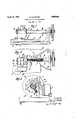
Figure l is a front elevation.
Figure 2 is a top plan view.
Figure 3 is a-partial section on line 3-3 of Figure 2.
The box plate a on which the entire device is mounted is provided with aperture forthe 3o passage of the shaft 0 on which the record carrier 6 is secured, the shaft 0 beingactuated by a motor and said motor also driving as for instance by means of a cord the pulley d and the threaded spindle e for the sound box f. The record carrier 12 supports that record blank 9 on which the sound reproducing grooves are to be impressed. The sound box actuating spindle e is disposed within a cylindrical casin h supported at one end only. The other record carrier and it is provided at its top with a cut out portion or slot 70 having the edges 2' and 7'. Those parts throu h which the sound box f is to be operative connected with the spindle e are'intende to project through said slot into the interior of the casing for coupling the-spindle with the sound box. A sleeve or bushin Z is slidably located surrounding the casin This bushingl is longitudinally slid'ab e on the casing r ce end projects over the h having arms m for a pivot pin n on which the sound box 7 is pivotally secured by means of bearing lu s o. The sleeve or bushing Z and the sound box 7 carried thereby are in releasable connection with the spindle e through a coupling element. This coupling element comprises a double armed lever pivoted on the pin 12. One arm p of said lever has a screw thread for engaging the thread of the spindle e, said spindle being accessible for the purpose of this engagement owing to the provision of the cut out portion In, in the casing h and the cut out portion in the bushing Z. In order to maintain the t readed arm p in engagement with the threaded spindie a spring 7' is provided Which rests on a I projection 8 of the arm 1?. The other arm t of the coupling member servesas a handle by means of which the arm 39 may be disen-. gaged from the spindle e and may then be automatically retained in disengaged position since the free end of the spring 7 will then enter a notch u on the arm 12.
The bushing Z is provided with a tubular extension '0 containing a springcontrolled slidable pin w, the inner end of which has a slanting surface w. Upon moving the bushing in a direction to lift the sound box from the record this pin enters the slot is of the cpsing h and then engages the edge i of said s ot. I
The operationis as follows: At the be- I ginning of the production of the record the sound box 7 is located above the edge of the record 9 and when the spindle e is rotated the sound box travels toward the center,
whereby two needles y produce a sound groove. In order to return the sound box to starting position or to any intermediate position it is only necessary to press against the handle it and thereby lift the arm 2 from the spindle 0. Owing to the spring 1 entering the notch u the arm isheld in disen aged position and then the sound box- 7 being raised from the record may be shifted along 95 the casin it together with the bushing l. In order to e able to move the sound boxto a position in which the needle y may readily be exchan d', the sound box may be rocked forward a ut the pin n and it may then which t I :as
be turned together with the bushin Z about the casing h until the inner end 0 the pin w enters the .slot k and then prevent a continuation of this rocking movement of the sound boxowing to its engagement with the edge 1'. In the return movement the slant-. ing surface :0 of the pin w engages the edge j and thereby causes the pin to be moved inward to eliminate any obstacle to the lowering of the sound box against the record.
I claimv 1; In apparatus for guiding the sound box in the production of records, a threaded revoluble spindle, a tubular casing in which said spindle is arranged, a sound box having a bushing which is mounted concentrically on the casing and for pivotal'movement thereon to permit raising and-lowerin of the sound box, a coupling member carrie by the sound box and engageable with the threaded spins dle, said casin and bushing having openings through whic the threaded spindle is exposed and through which said coupling is.
movable to and out of engagement with the spindle.
2. Apparatus as claimed in claim 1, in
e bushing is provided with a stop element to limit its rotary movement about the spindle casing, said stop element engaging in one terminal position an edge 11 of the casing and said stop element being provided with a slanting sui'face me which upon return movement of the bushing slides over the other edge of the casing.
3. Apparatus as claimed in claim' 1, in
whichlthe bushing is provided with a stop element to limit its rotary movement about the spindle casing, said stop element engaging in one terminal position an edge of the casing and said stop element being provided with a slanting surface which upon return movement of the-bushing slides over the other edge of the casing and also including a spring active to normally engage the stop element with the casing.
, In testimony whereof I aflix nay-signature,
SIGMUND- KATSCHER.
Applications Claiming Priority (1)
| Application Number | Priority Date | Filing Date | Title |
|---|---|---|---|
| AT1855058X | 1930-01-30 |
Publications (1)
| Publication Number | Publication Date |
|---|---|
| US1855058A true US1855058A (en) | 1932-04-19 |
Family
ID=3689130
Family Applications (1)
| Application Number | Title | Priority Date | Filing Date |
|---|---|---|---|
| US457280A Expired - Lifetime US1855058A (en) | 1930-01-30 | 1930-05-29 | Sound box guiding mechanism |
Country Status (1)
| Country | Link |
|---|---|
| US (1) | US1855058A (en) |
Cited By (1)
| Publication number | Priority date | Publication date | Assignee | Title |
|---|---|---|---|---|
| US2561466A (en) * | 1944-09-12 | 1951-07-24 | Dictaphone Corp | Phonograph mechanism |
-
1930
- 1930-05-29 US US457280A patent/US1855058A/en not_active Expired - Lifetime
Cited By (1)
| Publication number | Priority date | Publication date | Assignee | Title |
|---|---|---|---|---|
| US2561466A (en) * | 1944-09-12 | 1951-07-24 | Dictaphone Corp | Phonograph mechanism |
Similar Documents
| Publication | Publication Date | Title |
|---|---|---|
| US1855058A (en) | Sound box guiding mechanism | |
| US2866647A (en) | Dictating machine | |
| US3056606A (en) | Dictating machine | |
| US2127593A (en) | Phonograph | |
| US2181112A (en) | Sound reproducing apparatus for endless band sound carriers | |
| US2117236A (en) | Dictating machine | |
| US2335586A (en) | Sound recorder and reproducer | |
| US3599988A (en) | Semiautomatic phonograph with radial arm | |
| US2270179A (en) | Tone arm trip mechanism for phonographs | |
| US1342872A (en) | Device for forming grooves in sound-records | |
| US2154029A (en) | Marking device for index blanks | |
| US2061224A (en) | Tracking device for gramophone sound recording attachments | |
| US2305680A (en) | Phonograph | |
| US1939412A (en) | Ejector lock and conditioning means for dictation machines | |
| GB314203A (en) | Improvements in repeating devices for talking machines | |
| US2280575A (en) | Phonograph | |
| US2012185A (en) | Multiple playing phonograph | |
| US3010724A (en) | Phonograph trigger mechanisms | |
| US2161483A (en) | Automatic phonograph | |
| US2452133A (en) | Phonographic apparatus | |
| US2130931A (en) | Drive for recording and reproducing devices | |
| US406573A (en) | edison | |
| US1408740A (en) | Automatic stop for talking machines | |
| US2180094A (en) | Sound box for dictating machines | |
| US2209835A (en) | Phonograph record resurfacing machine |