US1855021A - Doorlock - Google Patents
Doorlock Download PDFInfo
- Publication number
- US1855021A US1855021A US370698A US37069829A US1855021A US 1855021 A US1855021 A US 1855021A US 370698 A US370698 A US 370698A US 37069829 A US37069829 A US 37069829A US 1855021 A US1855021 A US 1855021A
- Authority
- US
- United States
- Prior art keywords
- bolt
- plate
- lock
- pivoted
- latch
- Prior art date
- Legal status (The legal status is an assumption and is not a legal conclusion. Google has not performed a legal analysis and makes no representation as to the accuracy of the status listed.)
- Expired - Lifetime
Links
- 210000003813 thumb Anatomy 0.000 description 6
- 210000003811 finger Anatomy 0.000 description 3
- GHOKWGTUZJEAQD-ZETCQYMHSA-N (D)-(+)-Pantothenic acid Chemical compound OCC(C)(C)[C@@H](O)C(=O)NCCC(O)=O GHOKWGTUZJEAQD-ZETCQYMHSA-N 0.000 description 1
- 238000010276 construction Methods 0.000 description 1
- 210000005069 ears Anatomy 0.000 description 1
- 230000000694 effects Effects 0.000 description 1
- 210000003414 extremity Anatomy 0.000 description 1
Images
Classifications
-
- E—FIXED CONSTRUCTIONS
- E05—LOCKS; KEYS; WINDOW OR DOOR FITTINGS; SAFES
- E05B—LOCKS; ACCESSORIES THEREFOR; HANDCUFFS
- E05B45/00—Alarm locks
- E05B45/02—Alarm locks with mechanically-operated bells
-
- Y—GENERAL TAGGING OF NEW TECHNOLOGICAL DEVELOPMENTS; GENERAL TAGGING OF CROSS-SECTIONAL TECHNOLOGIES SPANNING OVER SEVERAL SECTIONS OF THE IPC; TECHNICAL SUBJECTS COVERED BY FORMER USPC CROSS-REFERENCE ART COLLECTIONS [XRACs] AND DIGESTS
- Y10—TECHNICAL SUBJECTS COVERED BY FORMER USPC
- Y10S—TECHNICAL SUBJECTS COVERED BY FORMER USPC CROSS-REFERENCE ART COLLECTIONS [XRACs] AND DIGESTS
- Y10S70/00—Locks
- Y10S70/49—Locks with alarm
-
- Y—GENERAL TAGGING OF NEW TECHNOLOGICAL DEVELOPMENTS; GENERAL TAGGING OF CROSS-SECTIONAL TECHNOLOGIES SPANNING OVER SEVERAL SECTIONS OF THE IPC; TECHNICAL SUBJECTS COVERED BY FORMER USPC CROSS-REFERENCE ART COLLECTIONS [XRACs] AND DIGESTS
- Y10—TECHNICAL SUBJECTS COVERED BY FORMER USPC
- Y10S—TECHNICAL SUBJECTS COVERED BY FORMER USPC CROSS-REFERENCE ART COLLECTIONS [XRACs] AND DIGESTS
- Y10S70/00—Locks
- Y10S70/73—Thumb latch operator
-
- Y—GENERAL TAGGING OF NEW TECHNOLOGICAL DEVELOPMENTS; GENERAL TAGGING OF CROSS-SECTIONAL TECHNOLOGIES SPANNING OVER SEVERAL SECTIONS OF THE IPC; TECHNICAL SUBJECTS COVERED BY FORMER USPC CROSS-REFERENCE ART COLLECTIONS [XRACs] AND DIGESTS
- Y10—TECHNICAL SUBJECTS COVERED BY FORMER USPC
- Y10T—TECHNICAL SUBJECTS COVERED BY FORMER US CLASSIFICATION
- Y10T70/00—Locks
- Y10T70/50—Special application
- Y10T70/5093—For closures
- Y10T70/5155—Door
- Y10T70/5199—Swinging door
- Y10T70/5372—Locking latch bolts, biased
- Y10T70/5385—Spring projected
- Y10T70/5389—Manually operable
- Y10T70/55—Dogged bolt or connections
Definitions
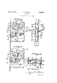
- Figure 1 is a side elevation of a lock embodying my invention.
- Figure 2 is a view at right angles to Figure 1.
- Figure 3 is a view similar to Figure 1 but showing the lock-bolt retracted.
- Figure 4 is a cross sectional view through the upper portion of Figure 1.
- the lock case is of known construction and includes heel plate 1, adapted to lie flush with the free edge of a door, andspaced apart side plates 2 and 3, the heel plate being provided with an opening through which the lock bolt 4 is projected, the latter being guided in its movements by posts 5 and 6 of the plate 2.
- On the bolt 4 is a stud 7 and the inner extremity of the bolt is flanged to provide a kicker plate 8.
- rIhe finger 9 of a pivoted lever 10 fits between the stud 7 and kicker plate 8 and effects movement of the bolt as the lever as actuated. Normally the lever is held in position to maintain the bolt projected by a weight 12 integrally formed with the lever and disposed at one side thereof above the finger 9.
- a recess 13 to receive the inner end of athumbpiece 14 pivoted between projecting ears 15 on the side plate 2, such inner end extending through an opening in such side plate.
- Downward pressure onV the thumb piece will lift the weight 12 and cause the finger 9 to bear against the kicker plate 8 and retract the bolt 4.
- lock bolt 4 may serve as a fixed lock I provide a means to prevent manipulation by the thumb piece 14.
- Such means includes a member 20 having sliding sied June 1 ⁇ 1, 1923. This application med June 13,Y
- This member 20 is tumbler controlled, the tumbler plate 25 being pivoted on the stud 21 and tensionedfby a spring 26.
- a longitudinal slot 27 of the plate 25 receives a pin 28 projecting from the member 20 and this pin, engaging one or the other of notches 29 communicating with the slot 27, is eective to prevent movement of the member 20 from locking to unlocking posiion or vice versa save by means of a key working through the key hole 30 and engaging the V-walls of recess 31 of the member 20 and the side of the pivoted plate 25, all in known manner.
- Audible notice is given of movements of the lock bolt by a bell 35 having hammers (not shown) actuated by a curved arm 36 connected therewith and with the bolt 4.
- a lock a casing, a sliding latch bolt supported therein, ya pivoted and weighted member for normally projecting said latch bolt in latching position, a thumb piece eX-A tending through said casing and engaging said pivoted and weighted member for actuating same to retract said bolt, a movable key controlled stop carried by said casing and adapted to engage said bolt to prevent actuation thereof by said thumb piece, and a key controlled tumbler carried in said casing and flatly engaging said movable stop in both its effective and ineffective positions.
- a lock a casing, a movable latch bolt supported therein, a pivoted and weighted member for normally projecting said latch bolt in latching position, said bolt having a laterally projecting portion against which a Y part of said weighted member bears when acting to retract said bolt, a thumb piece pivoted upon the outer wall of said casing and having a part projecting thereinto, said weighted member having ka recess in which the projecting part ,of said thumb piece is designed to engage whereby to retract said bolt through movement of said Weighted member, and a stop slidably mounted on one Wall of said easing and movable to engage said laterally projecting bolt portion to pref vent retraction of said bolt.
Landscapes
- Engineering & Computer Science (AREA)
- Mechanical Engineering (AREA)
- Hand Tools For Fitting Together And Separating, Or Other Hand Tools (AREA)
Description
April 19,l 1932.
C. HOFFMAN DORLOGK Original Filed June ll 1923 696/ 3 y J0 j 5.
A wm,
JJv l Patented Apr. 19, 1932 UNITED STATES PAT-NT CARL HOFFMAN, OF STAMFORD, CONNECTICUT, ASSIGNOR TO PAU/LINE HOFFMAN, OF ALLENTOWN, PENNSYLVANIA IDOORLOCK 1929. Serial This invention relates to door locks and particularly such as are employed for latching doors of stores and other places where notice of entry is desirable, and the object of my invention is to provide a latch of this character including improved and simple means for normally holding the latch projected, and improved and simple mechanism for retracting it, together with a. signal connected with the latch which is operable in all movements of the latch-bolt, and I likewise employ a tumbler-controlled means for preventing actuation of the latch bolt when desired.
In the drawings, Figure 1 is a side elevation of a lock embodying my invention. Figure 2 is a view at right angles to Figure 1. Figure 3 is a view similar to Figure 1 but showing the lock-bolt retracted. Figure 4 is a cross sectional view through the upper portion of Figure 1.
Referring to the several figures of the drawings, the lock case is of known construction and includes heel plate 1, adapted to lie flush with the free edge of a door, andspaced apart side plates 2 and 3, the heel plate being provided with an opening through which the lock bolt 4 is projected, the latter being guided in its movements by posts 5 and 6 of the plate 2. On the bolt 4 is a stud 7 and the inner extremity of the bolt is flanged to provide a kicker plate 8. rIhe finger 9 of a pivoted lever 10 fits between the stud 7 and kicker plate 8 and effects movement of the bolt as the lever as actuated. Normally the lever is held in position to maintain the bolt projected by a weight 12 integrally formed with the lever and disposed at one side thereof above the finger 9. In one face of the weight is a recess 13 to receive the inner end of athumbpiece 14 pivoted between projecting ears 15 on the side plate 2, such inner end extending through an opening in such side plate. Downward pressure onV the thumb piece will lift the weight 12 and cause the finger 9 to bear against the kicker plate 8 and retract the bolt 4.
In order that the lock bolt 4 may serve as a fixed lock I provide a means to prevent manipulation by the thumb piece 14. Such means includes a member 20 having sliding sied June 1`1, 1923. This application med June 13,Y
contact with the side plate 2 and guided in its movements by studs 21 and 22 of such plate respectively working in slots 23 and 24 of the member 20, and this plate when in lowermost position will lie back of the lock bolt 44 and block its retraction. This member 20 is tumbler controlled, the tumbler plate 25 being pivoted on the stud 21 and tensionedfby a spring 26. A longitudinal slot 27 of the plate 25 receives a pin 28 projecting from the member 20 and this pin, engaging one or the other of notches 29 communicating with the slot 27, is eective to prevent movement of the member 20 from locking to unlocking posiion or vice versa save by means of a key working through the key hole 30 and engaging the V-walls of recess 31 of the member 20 and the side of the pivoted plate 25, all in known manner.
Audible notice is given of movements of the lock bolt by a bell 35 having hammers (not shown) actuated by a curved arm 36 connected therewith and with the bolt 4.
'The advantages of my invention will be apparent.
I claim as my invention:
1. In a lock, a casing, a sliding latch bolt supported therein, ya pivoted and weighted member for normally projecting said latch bolt in latching position, a thumb piece eX-A tending through said casing and engaging said pivoted and weighted member for actuating same to retract said bolt, a movable key controlled stop carried by said casing and adapted to engage said bolt to prevent actuation thereof by said thumb piece, and a key controlled tumbler carried in said casing and flatly engaging said movable stop in both its effective and ineffective positions. f
2. In a lock, a casing, a movable latch bolt supported therein, a pivoted and weighted member for normally projecting said latch bolt in latching position, said bolt having a laterally projecting portion against which a Y part of said weighted member bears when acting to retract said bolt, a thumb piece pivoted upon the outer wall of said casing and having a part projecting thereinto, said weighted member having ka recess in which the projecting part ,of said thumb piece is designed to engage whereby to retract said bolt through movement of said Weighted member, and a stop slidably mounted on one Wall of said easing and movable to engage said laterally projecting bolt portion to pref vent retraction of said bolt. Y* A,
In testimony whereof I affix my signature.;
' CARL HOFFMAN.
Priority Applications (1)
| Application Number | Priority Date | Filing Date | Title |
|---|---|---|---|
| US370698A US1855021A (en) | 1929-06-13 | 1929-06-13 | Doorlock |
Applications Claiming Priority (1)
| Application Number | Priority Date | Filing Date | Title |
|---|---|---|---|
| US370698A US1855021A (en) | 1929-06-13 | 1929-06-13 | Doorlock |
Publications (1)
| Publication Number | Publication Date |
|---|---|
| US1855021A true US1855021A (en) | 1932-04-19 |
Family
ID=23460781
Family Applications (1)
| Application Number | Title | Priority Date | Filing Date |
|---|---|---|---|
| US370698A Expired - Lifetime US1855021A (en) | 1929-06-13 | 1929-06-13 | Doorlock |
Country Status (1)
| Country | Link |
|---|---|
| US (1) | US1855021A (en) |
-
1929
- 1929-06-13 US US370698A patent/US1855021A/en not_active Expired - Lifetime
Similar Documents
| Publication | Publication Date | Title |
|---|---|---|
| US3019043A (en) | Sliding door lock | |
| US1876081A (en) | Door latch | |
| US2270559A (en) | Door lock | |
| US2573061A (en) | Compartment lock | |
| US769767A (en) | Window-lock. | |
| US2682763A (en) | Garage door latch | |
| US3600021A (en) | Lock structure | |
| US2189992A (en) | Automobile door lock | |
| US1786521A (en) | Latch | |
| US2747906A (en) | Inside control for refrigerator door latches | |
| US1744988A (en) | Lock | |
| US3688531A (en) | Automatic locking system | |
| US1855021A (en) | Doorlock | |
| US1867694A (en) | Door lock | |
| US1107297A (en) | Lock. | |
| US3257135A (en) | Unit lock combination latch bolt and dead bolt retractor mechanism | |
| US1275938A (en) | Lock. | |
| US3107112A (en) | Latch bolt unit | |
| US1388712A (en) | Door-bolt | |
| US1560914A (en) | Door lock | |
| US1555829A (en) | Lock | |
| US2176969A (en) | Lock for vehicle doors | |
| US2329017A (en) | Combined door lock and ajar hook | |
| US1604946A (en) | Lock | |
| US3115357A (en) | Hotel room lock |