US1854947A - Water tube boiler - Google Patents
Water tube boiler Download PDFInfo
- Publication number
- US1854947A US1854947A US570322A US57032231A US1854947A US 1854947 A US1854947 A US 1854947A US 570322 A US570322 A US 570322A US 57032231 A US57032231 A US 57032231A US 1854947 A US1854947 A US 1854947A
- Authority
- US
- United States
- Prior art keywords
- boiler
- tubes
- economizer
- water tube
- drums
- Prior art date
- Legal status (The legal status is an assumption and is not a legal conclusion. Google has not performed a legal analysis and makes no representation as to the accuracy of the status listed.)
- Expired - Lifetime
Links
- XLYOFNOQVPJJNP-UHFFFAOYSA-N water Substances O XLYOFNOQVPJJNP-UHFFFAOYSA-N 0.000 title description 9
- 239000007789 gas Substances 0.000 description 12
- 238000010276 construction Methods 0.000 description 4
- 238000002485 combustion reaction Methods 0.000 description 2
- 238000010438 heat treatment Methods 0.000 description 2
- 238000012986 modification Methods 0.000 description 2
- 230000004048 modification Effects 0.000 description 2
- 239000004071 soot Substances 0.000 description 2
- 238000004140 cleaning Methods 0.000 description 1
- 230000007423 decrease Effects 0.000 description 1
- 239000000428 dust Substances 0.000 description 1
- 238000000034 method Methods 0.000 description 1
- 238000010025 steaming Methods 0.000 description 1
Images
Classifications
-
- F—MECHANICAL ENGINEERING; LIGHTING; HEATING; WEAPONS; BLASTING
- F22—STEAM GENERATION
- F22D—PREHEATING, OR ACCUMULATING PREHEATED, FEED-WATER FOR STEAM GENERATION; FEED-WATER SUPPLY FOR STEAM GENERATION; CONTROLLING WATER LEVEL FOR STEAM GENERATION; AUXILIARY DEVICES FOR PROMOTING WATER CIRCULATION WITHIN STEAM BOILERS
- F22D1/00—Feed-water heaters, i.e. economisers or like preheaters
- F22D1/02—Feed-water heaters, i.e. economisers or like preheaters with water tubes arranged in the boiler furnace, fire tubes or flue ways
Definitions
- the invention relates to water tube boilers and more particularly to such boilers with integral economizers of the bent tube type.
- the best known boilers of this type are the o Stirling, Heine and Connelly and consi-st of a boiler having four or more drums
- the lower drum in the boiler is commonly called the mud drum and is connected to two or more spaced drums by bent boiler tubes more or less inclined.
- the economizer is placed to the rear of the boiler and consists commonly of an upperand a lower drum connected by bent tubes, the upper drum ⁇ being connected by tubes to the rear upper drum of the boiler. It may, however, consist of one lower drum connected by tubes to the rear upper drum of the boiler.
- the economizer is traversed by the gases which have passed through the boiler ⁇ and is used to heat up the boiler feed water; the heat in the gases not transmitted to the boiler and economizer being lost up the stack.
- This invention has for its primary object (1) the most efficient. application of the'gases of combustion to the heating surfaces of both the boiler and the economizer so as to increase their economy (2) to reduce the draft loss through the unit so as to permit greater quantities of gas to be drawn through the unit with the available stack draft and thereby greatly increase the steaming capacity of the unit and (3) minimize the expansion strains on the economizer by equalizing the temperature in the tubes connecting the upper and lower drums.
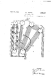
- Figure 1 is a vertical section through one form of boiler and economizer construction.
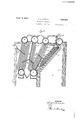
- Fig. 2 is a similar section through a modification.
- the boiler and economizer shown comprise the setting 1, iireboX 2,
- the boiler baffles comprising the sections 141 and 15 and the rear baffle the sections 16 and 39 17', the sections 111 and 16 extending longitudinally of the tubes and theI sections 15 and 17 extending transversely of the tubes.
- Y The gas outlet from the Vboiler setting is through the upper rear 'opening 22.
- 3F ig. 2 shows'another application of the invention, 'n wh'ch there is ysome modification of the baiiiing, and in'which a superheater of the loop typev is shown, such superheater lying in part to the front of the second bank of tubes.
- the same reference numerals are used on the economizer and boiler parts as are used on Fig. 1.
- the loops or elements 23 of the superheater are connected to the headers 24 land lie in part between the first and second banks of tubes 3 and 4 and in part in the spaces between the front bank 3.
- the frontbaftle comprises the three sections 25, 26, and 27 arranged as shown, with the section 27 acting as a gas seal to prevent the gases from by-passing the superheater at this point.
- the baiiie sections29, 80 and 31, are similar to and correspond in function with the sections V17, 18 and 19, of the Fig. lconstructionr; V Y
- the cross baiiing arrangement increases efficiency as compared with the longitudinal baffling heretofore employed with water tube boilers having economizers, gases flowing transversely across tubular surfaces transmit their heat more rapidly and completely'than where flowing parallel to such surfaces, due probably to greater turbulence, more intimate contactand direct impingment.
- the present arrangement insures cross flow both in the boiler and economizer, instead of the customary longitudinal ow in one or both.
- the construction decreases draft losses vvery materially as compared with customary longitudinal baflies, due in part to the wider passageways whichare possible. ⁇ VFriction losses are further reduced by the curved joining sections between the longitudinal 'and since the hot i The baiiie 28 leads from the rear steam drum u steam drum along transverse baille wall sections, and the tendency of soot, dust, and the like to collect at the junctures of the structures and thus clog the draft area is reduced. This feature also facilitates the work of steam and soot blowers in cleaning the tubes and baffles, in order to increase boiler efficiency.
- the method customarily used for passing the gases leaving the boiler vover the heating surface'of'the economizer is to flow them longitudinally along the tubes on the forward half of the economizer and turn them at the end and return them longitudinally along the rear half.
- the hot gases in the front half cause thev't-ubes to expand more than the comparatively cooler gases in the rear 'half cause the tubes in the rear half to expand, thereby introducing temperatures stresses in the drums tending to cause troublesome leaks where the tubes connect with the drums.
- What I claim is 1.
- baiiiing for the boiler including a baffle extending downward from the vicinity of the rear steam drum, along the tubes ofthe rear 4bank, and then to the front across the tubes, whereby the gases of combustion are circulated transversely of' the boiler tubes and delivered to the rear across the lower sections of said tubes, a baffle for the economizei ⁇ vextending laterally from the lower end of said longitudinal baffle across the economizer tubes, a second baille spaced above the first economizer baille, and extending in the reverse direction, and an outlet flue above the upper economizer baille.
- baffling for the boiler including a baille extending downward from the rear the back sides of the rear tober, 1931.
Landscapes
- Engineering & Computer Science (AREA)
- Physics & Mathematics (AREA)
- Thermal Sciences (AREA)
- Mechanical Engineering (AREA)
- General Engineering & Computer Science (AREA)
- Heat-Exchange Devices With Radiators And Conduit Assemblies (AREA)
Description
K. L, MARTIN April 19, 1932.
WATER TUBE BOILER Filed Oct. 22, 1931 2 Sheets-Sheet l K. L. MARTIN April 19, 19'32'.
The invention relates to water tube boilers and more particularly to such boilers with integral economizers of the bent tube type. The best known boilers of this type are the o Stirling, Heine and Connelly and consi-st of a boiler having four or more drums The lower drum in the boiler is commonly called the mud drum and is connected to two or more spaced drums by bent boiler tubes more or less inclined. The economizer is placed to the rear of the boiler and consists commonly of an upperand a lower drum connected by bent tubes, the upper drum` being connected by tubes to the rear upper drum of the boiler. It may, however, consist of one lower drum connected by tubes to the rear upper drum of the boiler.
The economizer is traversed by the gases which have passed through the boiler` and is used to heat up the boiler feed water; the heat in the gases not transmitted to the boiler and economizer being lost up the stack.
This invention has for its primary object (1) the most efficient. application of the'gases of combustion to the heating surfaces of both the boiler and the economizer so as to increase their economy (2) to reduce the draft loss through the unit so as to permit greater quantities of gas to be drawn through the unit with the available stack draft and thereby greatly increase the steaming capacity of the unit and (3) minimize the expansion strains on the economizer by equalizing the temperature in the tubes connecting the upper and lower drums. Certain embodiments of the invention are shown in the accompanying drawings, wherein:
Figure 1 is a vertical section through one form of boiler and economizer construction. 19 Fig. 2 is a similar section through a modification.
Referring to Fig. 1, the boiler and economizer shown comprise the setting 1, iireboX 2,
three banks of boiler tubes 3, 4 and 5, the drums 8, 9, 10 and 11, the economizer banks of tubes 6 and 7 the economizer drums upper and lower 12 and 13, the boiler baffles, the front baffles comprising the sections 141 and 15 and the rear baffle the sections 16 and 39 17', the sections 111 and 16 extending longitudinally of the tubes and theI sections 15 and 17 extending transversely of the tubes.
In the economizer, Vthe baiiiesextend transversely ofthe tubes, two sections 18 and 19 being used in this particular design. Y The gas outlet from the Vboiler setting is through the upper rear 'opening 22.
3F ig. 2 shows'another application of the invention, 'n wh'ch there is ysome modification of the baiiiing, and in'which a superheater of the loop typev is shown, such superheater lying in part to the front of the second bank of tubes. The same reference numerals are used on the economizer and boiler parts as are used on Fig. 1. The loops or elements 23 of the superheater are connected to the headers 24 land lie in part between the first and second banks of tubes 3 and 4 and in part in the spaces between the front bank 3. The frontbaftle comprises the three sections 25, 26, and 27 arranged as shown, with the section 27 acting as a gas seal to prevent the gases from by-passing the superheater at this point.
10. The baiiie sections29, 80 and 31, are similar to and correspond in function with the sections V17, 18 and 19, of the Fig. lconstructionr; V Y
The advantages incident to the constructions shown and described may be summarizedy as follows.
The cross baiiing arrangement increases efficiency as compared with the longitudinal baffling heretofore employed with water tube boilers having economizers, gases flowing transversely across tubular surfaces transmit their heat more rapidly and completely'than where flowing parallel to such surfaces, due probably to greater turbulence, more intimate contactand direct impingment. The present arrangement insures cross flow both in the boiler and economizer, instead of the customary longitudinal ow in one or both.
The construction decreases draft losses vvery materially as compared with customary longitudinal baflies, due in part to the wider passageways whichare possible.` VFriction losses are further reduced by the curved joining sections between the longitudinal 'and since the hot i The baiiie 28 leads from the rear steam drum u steam drum along transverse baille wall sections, and the tendency of soot, dust, and the like to collect at the junctures of the structures and thus clog the draft area is reduced. This feature also facilitates the work of steam and soot blowers in cleaning the tubes and baffles, in order to increase boiler efficiency.
If induced draft fans are used the driving power for the fan required for a given steam output will be materially reduced, and it will be possible with a given size fan to develop materially greater capacity in the boiler. This results in marked economy in iirst cost and operation.
The method customarily used for passing the gases leaving the boiler vover the heating surface'of'the economizer is to flow them longitudinally along the tubes on the forward half of the economizer and turn them at the end and return them longitudinally along the rear half. Obviously the hot gases in the front half cause thev't-ubes to expand more than the comparatively cooler gases in the rear 'half cause the tubes in the rear half to expand, thereby introducing temperatures stresses in the drums tending to cause troublesome leaks where the tubes connect with the drums.
Certain embodiments of the invention are shown in the accompanying `drawings but it should Vbe understood that there is a wide variation in the types lof boilers and economizers commonly used; and I do not limit the application of kmy invention to the exact construction shown unless otherwise limited by the terms andthe claims are applicable to all types.
What I claim is 1. In combination with a water tube boiler having upper steam drums and a lower mud drum with tubes connecting them and a vertical tube economizer lying back of the rear tubes of the boiler and having upper and lower drums, baiiiing for the boiler, including a baffle extending downward from the vicinity of the rear steam drum, along the tubes ofthe rear 4bank, and then to the front across the tubes, whereby the gases of combustion are circulated transversely of' the boiler tubes and delivered to the rear across the lower sections of said tubes, a baffle for the economizei` vextending laterally from the lower end of said longitudinal baffle across the economizer tubes, a second baille spaced above the first economizer baille, and extending in the reverse direction, and an outlet flue above the upper economizer baille.
2. In combination with a water tube boiler having upper steam drums and a lower mud drum with tubes connecting them and avertical tube economizer lying back of the rear tubes of the boiler and Ahaving upper and lower drums, baffling for the boiler including a baille extending downward from the rear the back sides of the rear tober, 1931.
KIN GSLEY L. MARTIN.
Priority Applications (1)
| Application Number | Priority Date | Filing Date | Title |
|---|---|---|---|
| US570322A US1854947A (en) | 1931-10-22 | 1931-10-22 | Water tube boiler |
Applications Claiming Priority (1)
| Application Number | Priority Date | Filing Date | Title |
|---|---|---|---|
| US570322A US1854947A (en) | 1931-10-22 | 1931-10-22 | Water tube boiler |
Publications (1)
| Publication Number | Publication Date |
|---|---|
| US1854947A true US1854947A (en) | 1932-04-19 |
Family
ID=24279186
Family Applications (1)
| Application Number | Title | Priority Date | Filing Date |
|---|---|---|---|
| US570322A Expired - Lifetime US1854947A (en) | 1931-10-22 | 1931-10-22 | Water tube boiler |
Country Status (1)
| Country | Link |
|---|---|
| US (1) | US1854947A (en) |
-
1931
- 1931-10-22 US US570322A patent/US1854947A/en not_active Expired - Lifetime
Similar Documents
| Publication | Publication Date | Title |
|---|---|---|
| US2594471A (en) | Heat exchange apparatus | |
| US1925222A (en) | Steam generator | |
| US1854947A (en) | Water tube boiler | |
| US1960770A (en) | Heat exchanger | |
| US1883293A (en) | Boiler with forced return circulation through furnace walls | |
| US1832769A (en) | Heat exchange tubing | |
| US2079104A (en) | Superheater | |
| US2123860A (en) | Steam generator | |
| US1826029A (en) | Waste heat boiler | |
| US1946666A (en) | Steam boiler | |
| US2374818A (en) | Steam generator | |
| US1656985A (en) | Power-generating system having air heater | |
| US1834782A (en) | Superheater | |
| US1696306A (en) | Fluid heater | |
| US1782205A (en) | Economizer | |
| US3221710A (en) | Closed circuit heat exchange system | |
| US149259A (en) | Improvement in steam-boilers | |
| US1790593A (en) | Steak generator | |
| US479648A (en) | Locomotive-boiler | |
| US704588A (en) | Steam-boiler. | |
| US1621505A (en) | Steam generator | |
| US1969406A (en) | Steam boiler | |
| GB218492A (en) | Improvements in and relating to steam boilers | |
| JP6936207B2 (en) | Boiler device | |
| US984430A (en) | Combined boiler, superheater, and feed-water heater. |