US1854914A - Core drill - Google Patents
Core drill Download PDFInfo
- Publication number
- US1854914A US1854914A US393602A US39360229A US1854914A US 1854914 A US1854914 A US 1854914A US 393602 A US393602 A US 393602A US 39360229 A US39360229 A US 39360229A US 1854914 A US1854914 A US 1854914A
- Authority
- US
- United States
- Prior art keywords
- cutters
- head
- holders
- cutter
- drill
- Prior art date
- Legal status (The legal status is an assumption and is not a legal conclusion. Google has not performed a legal analysis and makes no representation as to the accuracy of the status listed.)
- Expired - Lifetime
Links
Images
Classifications
-
- E—FIXED CONSTRUCTIONS
- E21—EARTH OR ROCK DRILLING; MINING
- E21B—EARTH OR ROCK DRILLING; OBTAINING OIL, GAS, WATER, SOLUBLE OR MELTABLE MATERIALS OR A SLURRY OF MINERALS FROM WELLS
- E21B10/00—Drill bits
- E21B10/08—Roller bits
- E21B10/20—Roller bits characterised by detachable or adjustable parts, e.g. legs or axles
-
- E—FIXED CONSTRUCTIONS
- E21—EARTH OR ROCK DRILLING; MINING
- E21B—EARTH OR ROCK DRILLING; OBTAINING OIL, GAS, WATER, SOLUBLE OR MELTABLE MATERIALS OR A SLURRY OF MINERALS FROM WELLS
- E21B10/00—Drill bits
- E21B10/02—Core bits
- E21B10/06—Roller core bits
Definitions
- My invention relates to core drills such as are used in deep well drilling in hard formations. It pertains more particularly to roller drills in which the cutters are formed and ⁇ mounted to roll upon the bottom of the hole.
- the invention includes the means by which the cutters are secured upon and held to their supports, and the particularly effective means by which said cutters are protected inftheirl mounting.
- A11 important object is to form the head and to mount the cutters thereon so that I can position the cutters well in advance of the body of the head, and still shroud the cutters for protection thereto.
- I also aim to form the drill so that the wall of the tubular head may be proportionately thin so as to enlarge the core barrel and yet secure a firm support for the cutters.
- the cutters are also designed to be of small diameter, and still cut suiiicient clearance for the drill head.
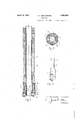
- Fig. 1 is a longi tudinal section through a drill colla-r and drill equipped according to my invention, taken approximately on the plane 1-1 of Fig. 2.
- Fig. 2 isa transverse section on the plane 2 2 of Fig. 1.
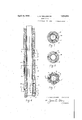
- Fig. 3 is an elevational detail of the cutter ilnd( 1ts mounting removed from the drill Fig. ⁇ 4 is a view similar to Fig. 1, but taken on the plane 4--4 of Fig. 7.
- Figs. 5, 6 and 7, are transverse sections character, it hasbeen my practice to mount v
- the head 1 is i made in one integral piece, and the lower end has a shoulder 2 in which sockets 3 are formed to receive posts 4 upon the cutter supporting elements.
- the wall of the head is ltapered downwardly adjacent the cutter holders to form a slight support at 6 for the inner sides of the cutter supporting elements.
- the .'said cutter supports are illustrated in Fig. 3.
- a head 5 on the inner side of which are formed ockets 7 to house the cutters 8, which are o frusto-conical shape, and mounted upon cutter shafts 9 vsecured in an inclined position .to the lower end of the holder.
- the cutters must be secured in advance of the drill, it is expedient to weld the cutter shafts to the holders 5; and I have shown a bond of welding material 10 aroundy the cutter shaft, the ⁇ upper side of which unites with the body of the holder.
- the shaft may be otherwise constructed to form an integral part of the holder if desired,
- the plate 11 secured to the head 5 of the holder so as to project along the inner side of the cutter to form art of the socket 7 and to bear against the Inner end of the cuttershaft, and thus keep the ushing fluid from washing the core.
- the plate 11 may be welded or otherwise secured to the head.
- the holder has the shank 4 shaped to fit the socket 3, and is therefore preferably cylindrical. Adjacent the upper end of the shank is a transverse groove 12 to receive a. tapered locking Y key 13 which projects through openings 14 in the ead and throu h said groove as seen in Fig. 2.
- the hea 1 of the drill has longitudinal flutes 15 therein, and the openings 14 terminate in said Iiutes.
- the grooves 12 in the shanks 4 are tapered somewhat, as shown and the keys 13 are also slightly tapered. when driven tightly in position the wedging effect of the pins draws the holders firmly into position, and the smaller ends of the keys are then bent over as shown at 16 to prevent removal in use.
- the head 1 is extended upwardly, and has an elongated shank 18 telescoin within -a drive sleeve 19, the upper en o which is adapted for connection with the drillstem.
- Two pins 20 screwed within thel shank project into a slot 21 in the sleeve and prevent relative rotation.
- the slot is long enough to allow a limited longitudinal movement so as to operate the core catcher.
- the core catcher includes do s .22 set in slots 26 in the side ofv the head etween the cutters and pivoted on axes 23.4
- the do are moved by rods connected at 24 to said dogs and extending upwardl in grooves 27 in the side ofthe head, and ave a resilient engagement through sprin s 28 with the lower end of the sleeve 19. t will therefore be seen that the raising of the Sleeve 19 relative to the shank 18, as allowed by the pin and slot engagement 20 and 21, will rotate the dogs into engagement with the core.
- Theilushing fluid passes downwardly between the core barrel 29 and the shank into passages 30 in the drill head and through reglstering assages 3 1 in the posts of the holders to the soc ets 7 in which the cutters are mounted.
- the flushing fluid has a comparatively straight passage from v the drill stem to the cutters so that a stron 4,5 stream of flushing fluid ma be directe against the cutters, and'as t e cutters are housed, a strong nozzle effect of the fluid passage and the socket 7 will assure that the cutters are kept free of material.
- cutters are separately mounted on their holders in the shop, and can be easiy fixed in sltlon in the drill head when esired.
- the walls of. thehead may be thinner, thus ⁇ ,allowing a larger core garrel and a larger core.
- the cutters may be of smaller diameter and can, be well housed, to obtain better action of the flushing fluid.
- a core drill including a tubular head, having a plurality of sockets in its forward end, cutter holders, posts on said holders shaped to fit said sockets, transverse locking keys engaging said posts, pockets in the lower ends of said holders, cutter pins sup orted in a bond of welding material on sai holders, and cutters on said pins in said pockets.
- a core drill including a tubular head, having socketsin its lower end, cutter holders, osts thereon secured in said sockets, rotata le cutters mounted on the lower ends of said holders, and means .on said holders to house the inner sides of said cutters.
- a core drill including a tubular head, having sockets in its lower end, cutter holders, posts thereon secured in said sockets,l rotatable cutters mounted on the lower ends of said holders, inclined cutter shafts for said cutters, and plates on said holders bearing against the inner ends of each of said shafts and serving to house the inner sides of said cutters adjacent the core.
- a core drill including a tubular head, havingsockets in its lower end, cutter holders, osts thereon secured in said sockets, 1'0- tata le cutters mounted on the lower ends of said holders, and plates secured to the inner sides of said holders to house the inner sides of said cutters adjacent the core.
- Cutter holders for core bits ada ted to be removably vsecured thereto said olders includedin a head, a post, said head having a lower soc et, a cutter shaft and a cutter thereon, said shaft bein welded on its upper side to the lower end o said head, and a. plate sel cured to said head and adapted to bear against the inner side ofsaid cutter and said shaft.
- a core bit including a tubular head having comparatively thin walls, cutter holders, posts on said holders held detachably within'sockets in said head, and cutters mounted on said holders to goject in advance of the head, said cutters ing housed on. their inner sides.
Landscapes
- Engineering & Computer Science (AREA)
- Life Sciences & Earth Sciences (AREA)
- Geology (AREA)
- Mining & Mineral Resources (AREA)
- Mechanical Engineering (AREA)
- Physics & Mathematics (AREA)
- Environmental & Geological Engineering (AREA)
- Fluid Mechanics (AREA)
- General Life Sciences & Earth Sciences (AREA)
- Geochemistry & Mineralogy (AREA)
- Processing Of Stones Or Stones Resemblance Materials (AREA)
- Drilling Tools (AREA)
Description
April .19, 1932. l.. H. WELLENSIEK CORE DRILL 2 Sheet's-Sheet Fiied sept. 19, 1929 LJL. WELLENvS/L'K 'VENTOR BY (A'AA' MM TTORNEY GORE DRILL' Filed Sept.- 19, 1929 2 Sheets-Shee-TI 2 L. H. WELLENS/EK /NVQeNTo/e 12x/lbum AM ATTORNEY Patented 19, 1.932l
UNITED` STATES lPATENT OFFICE LOUIS HfWELLENSIEiK, OF HOUSTON, TEXAS, ASSIGNOR TO"HUGES VTOOL OOHPANY, Ol'
' HOUSTON, TEXAS, A. CORPORATION 0F TEXAS CORE DRILL application mea september 19, 19211.v serial No. 393,602.
My invention relates to core drills such as are used in deep well drilling in hard formations. It pertains more particularly to roller drills in which the cutters are formed and `mounted to roll upon the bottom of the hole.
Itis an object of the invention to provide a core drill in which the cutters may be separately mounted upon Shanks removably se-` cured in the drill head, and hence capable of quick replacement in the field. i
The invention includes the means by which the cutters are secured upon and held to their supports, and the particularly effective means by which said cutters are protected inftheirl mounting. l
A11 important object is to form the head and to mount the cutters thereon so that I can position the cutters well in advance of the body of the head, and still shroud the cutters for protection thereto.
I am also enabled to get an eicctive How of 4. the flushing fluid directly upon the cutters to flush them free of material thereon.
I also aim to form the drill so that the wall of the tubular head may be proportionately thin so as to enlarge the core barrel and yet secure a firm support for the cutters.
The cutters are also designed to be of small diameter, and still cut suiiicient clearance for the drill head.
In the drawings herewith, Fig. 1 is a longi tudinal section through a drill colla-r and drill equipped according to my invention, taken approximately on the plane 1-1 of Fig. 2.
Fig. 2 isa transverse section on the plane 2 2 of Fig. 1.
Fig. 3 is an elevational detail of the cutter ilnd( 1ts mounting removed from the drill Fig.` 4 is a view similar to Fig. 1, but taken on the plane 4--4 of Fig. 7.
Figs. 5, 6 and 7, are transverse sections character, it hasbeen my practice to mount v In my present structure, the head 1 is i made in one integral piece, and the lower end has a shoulder 2 in which sockets 3 are formed to receive posts 4 upon the cutter supporting elements. Inside the sockets 3, the wall of the head is ltapered downwardly adjacent the cutter holders to form a slight support at 6 for the inner sides of the cutter supporting elements. l
The .'said cutter supports are illustrated in Fig. 3. There is a head 5 on the inner side of which are formed ockets 7 to house the cutters 8, which are o frusto-conical shape, and mounted upon cutter shafts 9 vsecured in an inclined position .to the lower end of the holder. As the cutters must be secured in advance of the drill, it is expedient to weld the cutter shafts to the holders 5; and I have shown a bond of welding material 10 aroundy the cutter shaft, the` upper side of which unites with the body of the holder. The shaft may be otherwise constructed to form an integral part of the holder if desired,
,inner plate 11 secured to the head 5 of the holder so as to project along the inner side of the cutter to form art of the socket 7 and to bear against the Inner end of the cuttershaft, and thus keep the ushing fluid from washing the core. The plate 11 may be welded or otherwise secured to the head.
In the other set, the lower end of the cutter' is inclined outwardly and no plate 11 1s necessary. y v
The holder has the shank 4 shaped to fit the socket 3, and is therefore preferably cylindrical. Adjacent the upper end of the shank is a transverse groove 12 to receive a. tapered locking Y key 13 which projects through openings 14 in the ead and throu h said groove as seen in Fig. 2. The hea 1 of the drill has longitudinal flutes 15 therein, and the openings 14 terminate in said Iiutes. The grooves 12 in the shanks 4 are tapered somewhat, as shown and the keys 13 are also slightly tapered. when driven tightly in position the wedging effect of the pins draws the holders firmly into position, and the smaller ends of the keys are then bent over as shown at 16 to prevent removal in use.
' The head 1 is extended upwardly, and has an elongated shank 18 telescoin within -a drive sleeve 19, the upper en o which is adapted for connection with the drillstem.
- 'The driving connection between the shank 18 and the sleeve 19 is shown in Figs. 4 and 5.
Two pins 20 screwed within thel shank project into a slot 21 in the sleeve and prevent relative rotation. The slot is long enough to allow a limited longitudinal movement so as to operate the core catcher.
The core catcher includes do s .22 set in slots 26 in the side ofv the head etween the cutters and pivoted on axes 23.4 The do are moved by rods connected at 24 to said dogs and extending upwardl in grooves 27 in the side ofthe head, and ave a resilient engagement through sprin s 28 with the lower end of the sleeve 19. t will therefore be seen that the raising of the Sleeve 19 relative to the shank 18, as allowed by the pin and slot engagement 20 and 21, will rotate the dogs into engagement with the core.
. Theilushing fluid passes downwardly between the core barrel 29 and the shank into passages 30 in the drill head and through reglstering assages 3 1 in the posts of the holders to the soc ets 7 in which the cutters are mounted. It is to be noted that the flushing fluid has a comparatively straight passage from v the drill stem to the cutters so that a stron 4,5 stream of flushing fluid ma be directe against the cutters, and'as t e cutters are housed, a strong nozzle effect of the fluid passage and the socket 7 will assure that the cutters are kept free of material.
"o In assembhng my improved cutters,the
cutters are separately mounted on their holders in the shop, and can be easiy fixed in sltlon in the drill head when esired. a
, scutter becomes worn and needs re lacement,
W the locking key 13 is removed an the holder 5 with its cutter thereon can then be with- `drawn from the head and anew one in- The great advanta of my im rovement,
however, lies in the ct that wit this construction of drill head and the securing of the cutters thereon I can mount the cutters so that they set well in advance of the head.
Also the walls of. thehead ma be thinner, thus`,allowing a larger core garrel and a larger core. Furthermore, the cutters may be of smaller diameter and can, be well housed, to obtain better action of the flushing fluid.
What I claim as new is:
1. A core drill including a tubular head, having a plurality of sockets in its forward end, cutter holders, posts on said holders shaped to fit said sockets, transverse locking keys engaging said posts, pockets in the lower ends of said holders, cutter pins sup orted in a bond of welding material on sai holders, and cutters on said pins in said pockets.
2. A core drill including a tubular head, having socketsin its lower end, cutter holders, osts thereon secured in said sockets, rotata le cutters mounted on the lower ends of said holders, and means .on said holders to house the inner sides of said cutters.
3. A core drill including a tubular head, having sockets in its lower end, cutter holders, posts thereon secured in said sockets,l rotatable cutters mounted on the lower ends of said holders, inclined cutter shafts for said cutters, and plates on said holders bearing against the inner ends of each of said shafts and serving to house the inner sides of said cutters adjacent the core.
4. A core drill including a tubular head, havingsockets in its lower end, cutter holders, osts thereon secured in said sockets, 1'0- tata le cutters mounted on the lower ends of said holders, and plates secured to the inner sides of said holders to house the inner sides of said cutters adjacent the core.
5. Cutter holders for core bits ada ted to be removably vsecured thereto, said olders includin a head, a post, said head having a lower soc et, a cutter shaft and a cutter thereon, said shaft bein welded on its upper side to the lower end o said head, and a. plate sel cured to said head and adapted to bear against the inner side ofsaid cutter and said shaft.
6. A core bit including a tubular head having comparatively thin walls, cutter holders, posts on said holders held detachably within'sockets in said head, and cutters mounted on said holders to goject in advance of the head, said cutters ing housed on. their inner sides.
' In testimony whereof, I hereunto aix my signature, this the 16th day of September, A. D. 1929. i
- LOUIS H. WELLENSIEK.
Priority Applications (1)
| Application Number | Priority Date | Filing Date | Title |
|---|---|---|---|
| US393602A US1854914A (en) | 1929-09-19 | 1929-09-19 | Core drill |
Applications Claiming Priority (1)
| Application Number | Priority Date | Filing Date | Title |
|---|---|---|---|
| US393602A US1854914A (en) | 1929-09-19 | 1929-09-19 | Core drill |
Publications (1)
| Publication Number | Publication Date |
|---|---|
| US1854914A true US1854914A (en) | 1932-04-19 |
Family
ID=23555429
Family Applications (1)
| Application Number | Title | Priority Date | Filing Date |
|---|---|---|---|
| US393602A Expired - Lifetime US1854914A (en) | 1929-09-19 | 1929-09-19 | Core drill |
Country Status (1)
| Country | Link |
|---|---|
| US (1) | US1854914A (en) |
-
1929
- 1929-09-19 US US393602A patent/US1854914A/en not_active Expired - Lifetime
Similar Documents
| Publication | Publication Date | Title |
|---|---|---|
| US2030722A (en) | Cutter assembly | |
| US3106973A (en) | Rotary drill bits | |
| US2244537A (en) | Well drilling bit | |
| US2375335A (en) | Collapsible drilling tool | |
| US2064273A (en) | Roller boring drill | |
| US1937742A (en) | Reamer for well drills | |
| US2557302A (en) | Combination drag and rotary drilling bit | |
| US2009742A (en) | Face bit | |
| US2976944A (en) | Percussion drill bit | |
| US1854914A (en) | Core drill | |
| US1375094A (en) | humason | |
| US2088770A (en) | Drill collar reamer | |
| US2201570A (en) | Rotary earth boring bit | |
| US1515819A (en) | Rotary well drill | |
| US2161000A (en) | Drill head | |
| US1899771A (en) | Blade type bit | |
| US2208530A (en) | Rotary well drill | |
| US2093633A (en) | Core drill | |
| US2054277A (en) | Stabilized well drilling bit | |
| IT8423810A1 (en) | DRILLING BIT FOR MINE EXCAVATIONS | |
| US2099859A (en) | Collapsible rotary core drill | |
| US1895610A (en) | Drill | |
| US2833521A (en) | Earth boring tools | |
| US2122584A (en) | Undercutting bucket | |
| US1786415A (en) | Well-drilling tool |