US1854883A - Conveyer - Google Patents
Conveyer Download PDFInfo
- Publication number
- US1854883A US1854883A US485450A US48545030A US1854883A US 1854883 A US1854883 A US 1854883A US 485450 A US485450 A US 485450A US 48545030 A US48545030 A US 48545030A US 1854883 A US1854883 A US 1854883A
- Authority
- US
- United States
- Prior art keywords
- belt
- chute
- casing
- trough
- cotton
- Prior art date
- Legal status (The legal status is an assumption and is not a legal conclusion. Google has not performed a legal analysis and makes no representation as to the accuracy of the status listed.)
- Expired - Lifetime
Links
- 229920000742 Cotton Polymers 0.000 description 12
- 239000000463 material Substances 0.000 description 11
- 238000007599 discharging Methods 0.000 description 7
- 230000035508 accumulation Effects 0.000 description 4
- 238000009825 accumulation Methods 0.000 description 4
- 238000010276 construction Methods 0.000 description 2
- 230000004048 modification Effects 0.000 description 2
- 238000012986 modification Methods 0.000 description 2
- 241000287181 Sturnus vulgaris Species 0.000 description 1
- 238000009434 installation Methods 0.000 description 1
- 239000002184 metal Substances 0.000 description 1
- 238000000638 solvent extraction Methods 0.000 description 1
Images
Classifications
-
- D—TEXTILES; PAPER
- D01—NATURAL OR MAN-MADE THREADS OR FIBRES; SPINNING
- D01G—PRELIMINARY TREATMENT OF FIBRES, e.g. FOR SPINNING
- D01G23/00—Feeding fibres to machines; Conveying fibres between machines
- D01G23/02—Hoppers; Delivery shoots
- D01G23/04—Hoppers; Delivery shoots with means for controlling the feed
- D01G23/045—Hoppers; Delivery shoots with means for controlling the feed by successive weighing; Weighing hoppers
Definitions
- a further and-more specific object of theiinlvention lis to provide, ⁇ in -a ⁇ devicefof '.thevcharactor 4set forth, means for carrying ofi' such material as may find its way to the upper surface of the lower belt run and which will be operative for this purpose while the machine is running.
- a still further object of the invention is to furnish cotton discharge means for removing accumulations of cotton from the lower run of a belt distributor, and which includes one of the standard pulleys about which the belt is trained.
- a further object of the invention is to pro- Y vide novel means whereby the accumulation of cotton or other material, between the distributor belt and its carrying pulleys or guides, may be automatically carried olf without necessitating the stopping of the machine,the invention being readily applicable to standard belt distributor constructions 30, i930. FSeialNo. 4853450.
- the :invention also resides in ⁇ certain .novel features of construction, combination and .-ar-
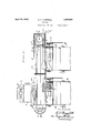
- v Figure .l is a sideelevational Wiempartly broken vand partly in sections and illustrating the application of [my invention :to adjacentcotton gin feedersyand Figure .2 is a sectional yiew. taken on .the line 2-2 of Figurefl.
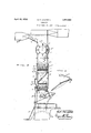
- Figure -3 is :a perspective -v-iew -of [the vde- 'iie ctor i chute.
- the lineal transverse partitioning memfber 10b beneath ⁇ the upper'run of belt 5 supports Vsuch runandprovides,withzthesidesof the casing 4, yan upper trough receiving 'the cotton :fromthe separator 8.
- Thebelt carries the cotton in the direction ofthe arrows ,I
- the deflector chute 11 is secured as at 12l to a cross bar 12 which in turn is carried by two uprights 13,-one at each side of the casing 4.
- the deflector chute 11 is preferably of sheet metal as is the companion chute 14.
- the companion chute 14 may be readily applied to standard belt conveyer casings by simply cutting an opening in the side wall thereof. It is a very simple matter to apply both chutes 11, 14 as the installation thereof in no way interferes with the usual operation of the distributor and necessitates no changes in the location of any of the parts entering thereinto.
- valve or cutoff unit 31 above the feeders 3 has been made the subject of a separate application for patent, as has also the separator unit 8.
- a material supply distributor comprising an elongated casing closed at one end and open at the other and providing upper and lower trough portions, an endless belt distributor having material engaging elements and working in said troughs, said belt receiving material from above said upper trough and carrying it toward said closed end and into said lower trough, rotatable pulleys supporting sai-d belt at each end and about which the same is trained, the bottom of the lower ⁇ trough having discharge openings intermediate its ends, a chute member between said troughs and adjacent the pulley at the discharge end of said casing and discharging laterally of the lower run of said belt, said chute member receiving from between said aforementioned pulley and the upper run of said belt such material as has reached the ⁇ upper side of the lower run of the belt,
- a second chute member carried by said casing and receiving material from said first mentioned chute, and said second chute member discharging into said lower trough beneath the lower run of said belt.
- a conveyer of the class described including a trough like casing, an endless conveyer belt in said casing supporting means for said belt and including a rotatable mem ber at one loop thereof, a deflector adjacent said rotatable member and receiving material from between said member and the top flight of said belt, said deflector .discharging laterally of the lower run of said belt, a chute at one side of said casing opposite said deiiector and receiving material therefrom, and said chute discharging into said trough beneath said lower conveyer run.
- a conveyer of the class described including a trough like casing, an endless conveyer belt in said casing supporting means for said belt and including a rotatable member at one loop thereof, a deflector adjacent said rotatable member and receiving material from between said lmember and the top flight of said belt, said deiiector discharging laterally of the lower run of said belt, a chute at one side of said casing opposite said defl-ector and receiving material therefrom, said chute discharging into said trough beneath said lower conveyer run, supporting means n for said deflector and chute and including vertical posts carried by Said casing, and a carrier for said deflector comprising a cross member secured to sai-d posts between the upper and lower runs of said belt.
Landscapes
- Engineering & Computer Science (AREA)
- Textile Engineering (AREA)
- Feeding Of Articles To Conveyors (AREA)
Description
April 19, 1932. E. F. CAMPBELL CONVEYER 2 Sheets-Sheet l Filed Sept. 30, 1930 April 19, 1932. l E. F, CAMPBELL 1,854,883
CONVEYER Filed Sept. 50, 1930 2 Sheets-Sheet 2 Patented Apr. 19, 1932 nNiiTED stares fr Are Nr :ori-ice .ERNEST l". aCAMPBELL, OF COLUMBUS, GEORGIA, ASSIGNOR TO L'UMMUS COTTON GN .CQMBANY, OF COLUMBUS GEORGIA, A CORPOR-ATXON OF GEORGIA OON'VEYER Application filed September My invention relates to improvements in conv-.eyers `'broadly :and has special reference to .fhelt distributors such -as are used in con- .=nection with zcottonfhandling, machinery `and fitheglike.
.The :main diiculty experienced in I,the use :of .the beltdistr'ibutor forsupplying gin feed- .ers,is that ,seed cottoniworks up between the zbelt .and 4.trough iand accumulates upon the upperlsidefofithe 'lower run of the belt. .'Such .progressively increasing `,accumulation isf carried around .the belt v-lcarr-ying V,pulley fat one .fendof the vmachine ,and again drops on the belt distributor,vfor cotton gin feeders for :the
like, novel meansiffor preventing the accumulation of cotton 'upon the iupper side L of the flower runoffthe jbe'lt. i
A further and-more specific object of theiinlvention lis ,to provide, `in -a `devicefof '.thevcharactor 4set forth, means for carrying ofi' such material as may find its way to the upper surface of the lower belt run and which will be operative for this purpose while the machine is running.
A still further object of the invention is to furnish cotton discharge means for removing accumulations of cotton from the lower run of a belt distributor, and which includes one of the standard pulleys about which the belt is trained.
A further object of the invention is to pro- Y vide novel means whereby the accumulation of cotton or other material, between the distributor belt and its carrying pulleys or guides, may be automatically carried olf without necessitating the stopping of the machine,the invention being readily applicable to standard belt distributor constructions 30, i930. FSeialNo. 4853450.
at :small expense and Awithout substantial modification.
The :invention also resides in `certain .novel features of construction, combination and .-ar-
rangementof the various parts and .in-modes ofioperationV-all of which willlbe readily apparent to .those-skilled in the .artupon reference to the accompanying .dra-wings in .c011- :nection with the ydetailed :descriptive Yfmatter appearing hereinafter.
ln `the drawings, v Figure .l is a sideelevational Wiempartly broken vand partly in sections and illustrating the application of [my invention :to adjacentcotton gin feedersyand Figure .2 is a sectional yiew. taken on .the line 2-2 of Figurefl.
Figure -3 :is :a perspective -v-iew -of [the vde- 'iie ctor i chute.
Referring specifically fto `the drawings? 1wherein :the isame reference characters have been used Ito designate the same parts in :all Niews, numeral `3- denotes -a pair `of Vcotton gin feeders which support ,thefcasing-lgof the belt distributor `5, which is trained .0ve1 the pulleys '-6, fa ,shown fjourna-lled :upon shafts ,7. YThe belt 5 has the usualfconveying spikes azandrreceives the cotton from the pneumatic `convefyorqpi-pe 8*:through-theseparatorfdisfcharging through the opening-8a in thecasin g 4. -The separator has the ydriven :discharge element 8c as shown. For purposes .of con- 1 venience numeral 9 isused `to :designate the foot-ton. l
The lineal transverse partitioning memfber 10b beneath `the upper'run of belt 5 supports Vsuch runandprovides,withzthesidesof the casing 4, yan upper trough receiving 'the cotton :fromthe separator 8. Thebeltcarries the cotton in the direction ofthe arrows ,I
it is being grinned the :surplus -will .be ,dis- 1i; I;
charged through the opening 10c at the discharge end of the casing 4.
Ordinarily, a substantial mass of cotton 9 will be progressively accumulated upon the lower side of the belt run to be carried around the pulley 6 again and again,-such cotton leaving the pulley at the point where the top run of the belt parts and dropping again upon the lower run. rlhe manifest objections to this have already been pointed out, and as has been stated, the machine must be frequently stopped and cleaned to assure proper travel of the belt 5.
As shown, I overcome this difliculty by the use of the defiector chute 11 disposed adjacent to, and receiving the cotton from the pulley 6 as shown in Figure 1,-such chute 11 being open at the side toward the pulley and having its sloping bottom discharging laterally of the belt 5 into a companion chute 14 whose discharge end 14a communicates with the trough 10 beneath the belt 5 as shown in Figure 2. Y
The deflector chute 11 is secured as at 12l to a cross bar 12 which in turn is carried by two uprights 13,-one at each side of the casing 4. The deflector chute 11 is preferably of sheet metal as is the companion chute 14. As to the companion chute 14,-this is suitably secured to the casing 4 and may be fastened to one of the uprights 13 (Figure 2).
The companion chute 14 may be readily applied to standard belt conveyer casings by simply cutting an opening in the side wall thereof. It is a very simple matter to apply both chutes 11, 14 as the installation thereof in no way interferes with the usual operation of the distributor and necessitates no changes in the location of any of the parts entering thereinto.
It is to be understood that the foregoing is to be taken merely as the now preferred mechanical expression of my invention which is obviously susceptible of considerable change and modification within the spirit and scope of the subject matter claimed hereinafter.
The valve or cutoff unit 31 above the feeders 3 has been made the subject of a separate application for patent, as has also the separator unit 8.
Having thus described my invention, what I claim as new and desire to secure by Letters Patent is:
1. A material supply distributor comprising an elongated casing closed at one end and open at the other and providing upper and lower trough portions, an endless belt distributor having material engaging elements and working in said troughs, said belt receiving material from above said upper trough and carrying it toward said closed end and into said lower trough, rotatable pulleys supporting sai-d belt at each end and about which the same is trained, the bottom of the lower` trough having discharge openings intermediate its ends, a chute member between said troughs and adjacent the pulley at the discharge end of said casing and discharging laterally of the lower run of said belt, said chute member receiving from between said aforementioned pulley and the upper run of said belt such material as has reached the `upper side of the lower run of the belt,
a second chute member carried by said casing and receiving material from said first mentioned chute, and said second chute member discharging into said lower trough beneath the lower run of said belt.
2. In a conveyer of the class described including a trough like casing, an endless conveyer belt in said casing supporting means for said belt and including a rotatable mem ber at one loop thereof, a deflector adjacent said rotatable member and receiving material from between said member and the top flight of said belt, said deflector .discharging laterally of the lower run of said belt, a chute at one side of said casing opposite said deiiector and receiving material therefrom, and said chute discharging into said trough beneath said lower conveyer run.
3. In a conveyer of the class described including a trough like casing, an endless conveyer belt in said casing supporting means for said belt and including a rotatable member at one loop thereof, a deflector adjacent said rotatable member and receiving material from between said lmember and the top flight of said belt, said deiiector discharging laterally of the lower run of said belt, a chute at one side of said casing opposite said defl-ector and receiving material therefrom, said chute discharging into said trough beneath said lower conveyer run, supporting means n for said deflector and chute and including vertical posts carried by Said casing, and a carrier for said deflector comprising a cross member secured to sai-d posts between the upper and lower runs of said belt.
In testimony whereof I aiiiX my signature.
ERNEST F. CAMPBELL.
Priority Applications (1)
| Application Number | Priority Date | Filing Date | Title |
|---|---|---|---|
| US485450A US1854883A (en) | 1930-09-30 | 1930-09-30 | Conveyer |
Applications Claiming Priority (1)
| Application Number | Priority Date | Filing Date | Title |
|---|---|---|---|
| US485450A US1854883A (en) | 1930-09-30 | 1930-09-30 | Conveyer |
Publications (1)
| Publication Number | Publication Date |
|---|---|
| US1854883A true US1854883A (en) | 1932-04-19 |
Family
ID=23928213
Family Applications (1)
| Application Number | Title | Priority Date | Filing Date |
|---|---|---|---|
| US485450A Expired - Lifetime US1854883A (en) | 1930-09-30 | 1930-09-30 | Conveyer |
Country Status (1)
| Country | Link |
|---|---|
| US (1) | US1854883A (en) |
-
1930
- 1930-09-30 US US485450A patent/US1854883A/en not_active Expired - Lifetime
Similar Documents
| Publication | Publication Date | Title |
|---|---|---|
| US1854883A (en) | Conveyer | |
| US2105889A (en) | Belt conveyer | |
| US3407918A (en) | Apparatus for breaking up and conveying fibrous textile materials | |
| US3532099A (en) | Cut tobacco feeder | |
| US1950729A (en) | Asparagus cutting machine | |
| GB976668A (en) | Conveyors | |
| US2066866A (en) | Continuous flow conveyer | |
| US2960212A (en) | Feeding apparatus for fibrous material | |
| GB1212267A (en) | A feeder for feeding moist material in bulk form | |
| US1336320A (en) | Feeder | |
| US3174619A (en) | Troughed belt conveyor | |
| GB1373872A (en) | Feeders for bulk materials | |
| SU741818A1 (en) | Hopper for spraying mineral distributor | |
| FR2439829A1 (en) | DEVICE FOR RECEIVING AND GATHERING A FIBER WEB AT THE EXIT OF A CARD | |
| SU753940A1 (en) | Apparatus for distributing fibrous material among bins of machines operating in parallel | |
| US2196609A (en) | Conveyer | |
| US2787367A (en) | Belt conveyor | |
| US1766530A (en) | Grape-stripping machine | |
| US2106380A (en) | Conveyer-distributor for cotton and like materials | |
| USRE17782E (en) | A corpora | |
| US2365714A (en) | Continuous elevator | |
| GB465759A (en) | Improvements in or relating to means for conveying fibrous or granular material in an upward direction | |
| US1871583A (en) | Gravel washing machine | |
| US1740723A (en) | Feeder construction for harvester thrashers | |
| US1645324A (en) | Separating apron for green-pea-vine hullers |