US1854878A - Pasting machine - Google Patents
Pasting machine Download PDFInfo
- Publication number
- US1854878A US1854878A US241822A US24182227A US1854878A US 1854878 A US1854878 A US 1854878A US 241822 A US241822 A US 241822A US 24182227 A US24182227 A US 24182227A US 1854878 A US1854878 A US 1854878A
- Authority
- US
- United States
- Prior art keywords
- paste
- machine
- band
- roller
- belt
- Prior art date
- Legal status (The legal status is an assumption and is not a legal conclusion. Google has not performed a legal analysis and makes no representation as to the accuracy of the status listed.)
- Expired - Lifetime
Links
- 239000000463 material Substances 0.000 description 17
- 238000000576 coating method Methods 0.000 description 13
- 238000004140 cleaning Methods 0.000 description 12
- 239000011248 coating agent Substances 0.000 description 11
- 239000012530 fluid Substances 0.000 description 10
- 239000002184 metal Substances 0.000 description 5
- 239000003292 glue Substances 0.000 description 3
- 239000000853 adhesive Substances 0.000 description 2
- 230000001070 adhesive effect Effects 0.000 description 2
- 238000007598 dipping method Methods 0.000 description 2
- 239000013013 elastic material Substances 0.000 description 2
- 238000005485 electric heating Methods 0.000 description 2
- 239000004744 fabric Substances 0.000 description 2
- 238000010438 heat treatment Methods 0.000 description 2
- 238000000034 method Methods 0.000 description 2
- 230000001105 regulatory effect Effects 0.000 description 2
- XKZCXMNMUMGDJG-AWEZNQCLSA-N (2s)-3-[(6-acetylnaphthalen-2-yl)amino]-2-aminopropanoic acid Chemical compound C1=C(NC[C@H](N)C(O)=O)C=CC2=CC(C(=O)C)=CC=C21 XKZCXMNMUMGDJG-AWEZNQCLSA-N 0.000 description 1
- 229910001369 Brass Inorganic materials 0.000 description 1
- 235000002918 Fraxinus excelsior Nutrition 0.000 description 1
- 102100026933 Myelin-associated neurite-outgrowth inhibitor Human genes 0.000 description 1
- 230000001154 acute effect Effects 0.000 description 1
- 239000002956 ash Substances 0.000 description 1
- 239000010951 brass Substances 0.000 description 1
- 235000019506 cigar Nutrition 0.000 description 1
- KTRGHLZBDIJZLQ-UHFFFAOYSA-N elatine Natural products CCN1CC2(CCC(OC)C34C2C(OC)C5(OCOC56CC(OC)C7CC3(O)C6C7OC)C14)OC(=O)c8ccccc8N9C(=O)CC(C)C9=O KTRGHLZBDIJZLQ-UHFFFAOYSA-N 0.000 description 1
- 230000004048 modification Effects 0.000 description 1
- 238000012986 modification Methods 0.000 description 1
- 230000000630 rising effect Effects 0.000 description 1
- 238000007790 scraping Methods 0.000 description 1
- 239000002699 waste material Substances 0.000 description 1
- XLYOFNOQVPJJNP-UHFFFAOYSA-N water Substances O XLYOFNOQVPJJNP-UHFFFAOYSA-N 0.000 description 1
Images
Classifications
-
- B—PERFORMING OPERATIONS; TRANSPORTING
- B05—SPRAYING OR ATOMISING IN GENERAL; APPLYING FLUENT MATERIALS TO SURFACES, IN GENERAL
- B05C—APPARATUS FOR APPLYING FLUENT MATERIALS TO SURFACES, IN GENERAL
- B05C1/00—Apparatus in which liquid or other fluent material is applied to the surface of the work by contact with a member carrying the liquid or other fluent material, e.g. a porous member loaded with a liquid to be applied as a coating
- B05C1/04—Apparatus in which liquid or other fluent material is applied to the surface of the work by contact with a member carrying the liquid or other fluent material, e.g. a porous member loaded with a liquid to be applied as a coating for applying liquid or other fluent material to work of indefinite length
- B05C1/08—Apparatus in which liquid or other fluent material is applied to the surface of the work by contact with a member carrying the liquid or other fluent material, e.g. a porous member loaded with a liquid to be applied as a coating for applying liquid or other fluent material to work of indefinite length using a roller or other rotating member which contacts the work along a generating line
- B05C1/0826—Apparatus in which liquid or other fluent material is applied to the surface of the work by contact with a member carrying the liquid or other fluent material, e.g. a porous member loaded with a liquid to be applied as a coating for applying liquid or other fluent material to work of indefinite length using a roller or other rotating member which contacts the work along a generating line the work being a web or sheets
- B05C1/0834—Apparatus in which liquid or other fluent material is applied to the surface of the work by contact with a member carrying the liquid or other fluent material, e.g. a porous member loaded with a liquid to be applied as a coating for applying liquid or other fluent material to work of indefinite length using a roller or other rotating member which contacts the work along a generating line the work being a web or sheets the coating roller co-operating with other rollers, e.g. dosing, transfer rollers
Definitions
- the conveyor band is raised to a height of 3 millimetres which is effected by inserting a second bevelled metal plate and above the forward half of the band is fitted a laying-on table that is provided with two rollers arranged at an acute angle for feeding the material which is to be pasted and which is thus carried to the pasting path.
- Lifters fitted with rubber ing points are arranged at the end of the pasting path andabove the lifters an additional pressure roller is adjustably mounted in order to allow for material of any thick ness running out under uniform pressure and control.
- the machme By removing the laying-on table'the machme can also be used as a so-called travelling application board. This has the'advantage of always providing a flat path coated with fresh paste, because owing to the continuous slow rotation of the band the surface from which the paste has been drawn ofi disappears and asurface with fresh paste thereon appears.
- V In the earlier pasting and gumming machines, with single or several rollers, the material is fed by means of two feed rollers tothe actual pasting roller.
- a pressure batten is arranged between the pasting roller and the feed rollers but the material which is to be pasted usually remains suspended between the feed rollers, if it is not smooth or if the feed rollers absorb moisture from the hot paste, because the feedrollers are sit- Hated immediately over the hot paste box and remain in a heated condition even if a pro .slip or are diverted
- the present invention eliminates this de-- ing members.
- the distance of the transfer roller from the band can be adjusted so that the fluid is applied uniformly in any desired thickness of layer.
- the material which is to be damped with the fluid is fed to the conveyor band from a laying-on table and runs quite flat until it reaches the lifter roller.
- Two feed rollers are fitted-to the laying-on table which are driven by friction and hold the material down from the moment it is fed in. .At the delivery end is arranged an adjustable roller which holds the material down uniformly as it runs out so that the ends of the material receive a sufiicient supply of fluid.
- the laying-on device is placed at such a distance from the actual fluid'container that none of the steam rising from the hot fluid container can-reach the
- the present invention provides a heating device for the lower half of the horizontal band so that the hot paste does not cool if the band with its surface of paste stands still for any length of time.
- the same object can be attained by having a sufliciently large fluid container.
- the present invention makes provision for the band to be manually driven.
- the thickness of the coat having been adjusted, one and one only complete revolution is effected and the coated band is then filled up with about thirt or more strips of paper, such as are used or example in cigar factories; the strips are then removed one by one to be worked uE, and the process repeated as often as may e required.
- the same operation can also be effected in other departments, where small pieces of material are to be moistened with paste, glue, g'elatine or an impregnating matter.
- Frame mounts and fabrics can also be moistened with adhesive material rapidly and uniformly in this manner.
- material can also be moistened with adhesive matter, material which on one side is smooth but has uneven places on the other side, for example, decorative coatings, the material being laid flat, on to the band and pressed on gently have tobe applied in the hot state are maintained at any desired temperature by means of gas heating, electric heating, or by means of a hearth heated with hot ashes.
- the drive of the machine can be effected by hand, shafting, or from a separate motor; if a motor is used, the machine and the motor are mounted on one and the same base plate.
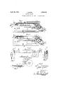
- Figure 1 is a side view of the combined means of differential wheels and reguby hand. Fluids which 9 machine, all the adjustable parts being shown diagrammatically.
- Figure 2 is a similar side view with the laying-on table and the lifters removed.
- Figure 4 shows the embedded cleaning apparatus to a larger scale and in the cleaning position close up to the transfer roller and the conveyor or coating band.
- Figure 5 shows the vertical position of the cleaning apparatus as seen' from below.
- Figure 6 shows the horizontal portion of the cleaning apparatus with the drainage holes seen from thefront turned towards the transfer roller.
- Figure 7 shows the lifters provided with rubber points and comprising two leaf spring clamps.
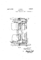
- Fig. 9 is an enlarged elevation, partly in section, of the means for regulating the transfer roller and the scrapin device, the near wall of the frame being broken away.
- Fig; 10 is a section on the line 1010, of Fig. 9.
- Figure 1 a is the fluid container which is surrounded b a water jacket I).
- the transfer roller 0 ips into the fluid container a.
- the coating belt d runs above the transfer roller 0 and by means of distance pieces on either side the thickness ofthe layer to be transferred to the coating belt is determined from time to time by operatin r the lever e, which is connected to a toothe segment and inion and is an adjusting lever with a rigidy coupled toothed wheel and is moved over the are e.
- f is a bearing member with a toothed segment, the second lever t secured thereto passes over a perforated scale.
- 9 and h are conveyor rollers with supporting discs for the horizontal conveyor band or coating belt d.
- i are lateral scrapers bearing against the surface of the transfer roller.
- k is a union for connection to a gas supply or an electric heating device can be connected up at this point.
- 1 is the paste or glue distributor for extremely fine coatings.
- m is a metal plate disposed between the conveyor rollers and h and represents a rigid support for the coating belt.
- n is a toothed wheel on the handle side.
- 0 is an adjustable pressure roller for holding both rigid and elastic materials down on the asted band..
- p is a chain for the toothed w eel conveyor when operated manually.
- q is the handle.
- 0* and s are the laying-on table and feed rollers, both being connected in such a manner that these parts can be simultaneously removed showing the machine as represented in Figure 2 and as used only as anap lication board.
- the feed rollers are frictiona ly connected together.
- t is the cleaning apparatus for the coating belt and transfer roller.
- u are ball r the remaining parts are the same as that of roller 1 is provided in
- Figure 2 the machine is shown as a travelling application board with the same parts, with t e exception of the layin -on table 1* and the feed rollers s that have en removed, the operation is otherwise the same as that of the machine shown in Figure 1.
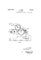
- Figure 3 is a modification of the machine shown in Figures 1 and 2.
- a special guide Figure 3 in order to prevent any deviation of the coating band,
- Figure 4 shows, to an enlarged scale, the vertical cleaning mem horizontally disposed.
- second cleaning batten. 2 shows the cleaning position of the coating band, 3 that of the cleaning position of the transfer roller.
- Figure 5 is the elevation Figure 6 is the ground 4. The circular and oval away the paste or glue.
- Flgure 7 shows lifters with lifting points; the lifters consist of leaf spring clamps (made of metal), the points being made of vulcanite. 4 and 5aresimilar parts of the clamps, 6 showing the inserted hfting point. The parts are marked or on the machine.
- Figure 8 shows lifters with spiral sprmg clamps. 7 and 10 are the springs which are connected to the cheeks 8 and 9 and into at 2 in Figure 1. plan at 3 of Figure oles serve to carry which the point 6 is pressed by means of a s rm
- the opposed bearing members f are journaled on stud bolts 16 which are screwed into the opposite walls to vof the frame.
- pinion wheels 14 mounted upon a shaft 15 which shaft is journaled in the opposite walls 40 of the frame.
- Shaft 15 carries at one end a lever e by means of which the pinions 14 may be rotated to f pivot the bearing members f on studs 16.
- Lever e may be held in adjusted position by a. pin engaging notches in the arcuate guide c. J ournaled in ball bearings u the members f is a shaft 13 disposed parallel with shaft 15 and carrying the transfer roller 0.
- Shaft 13 also carries a toothed wheel 3 which meshes with the toothed wheel 11 of the shaft 12 of the convegor roller 9.
- the shaft 12 is journaled all bearings u in the opposite' walls 'w of the frame.
- the scrapers i are screwed b wing screws 18 on a bar 17 which is fastene to eyes 19 on the opposite walls a; of the frame.
- On extensions of the bolts 16 are rotatably journaled the arms t of the sore r having the bars 2 and 3 for cleansing an scraping.
- Scraper arms ber connected to a t are held in adjusted position by bolts 20 engaging the spaces of teeth 21 in 'of the bearing members f.
- the 0 lows the ends andle 9 when rotated revolves the shafts of both toothed wheels n, which wheels are driven in unison by chain p. .Rotation of wheels 11. moves the drums g and h, and roller 0 by means of tor could be used-
- the paste in tank a which may be heated by means of jacket/b, is transferred to the coating belt 11 by the transfer roller 0 which dips into the paste in tank a, the roller a rotating in a clockwise direction as shown by. the arrow in Fig. 4.
- the upper run of belt (1 moves from right to-left as shown by the arrow on drum gin Fig. 4.
- the thickness belt d which runs over also rotates distributor gearing 3 Instead of crank handle 9 a small electric or other mo-' to operate the machine.
- ration of the machine is as fol of the layer of the paste thus transferred to the-belt d is regulated by operating lever 0,.
- Mani ulation of distributor I will permit avery coating to be spread upon the belt d.
- the sheets or strips, to which paste is to be ap-' plied, are fed upon the top run of belt d from the laying-on table 1' between the driven feed rollers s.
- the sheet is then carried by the belt (1 supported upon the table m to and under the delivery roll .0 which holds the sheet down upon the paste band d, and the sheet then pa es-over the lifters a: which deliver the pasi d sheet;
- the laying-on table r includin feed rollers s can be bodily removed (Flg.
- WhatIclaimisr 1 A pasting machine comprising a paste tank, a support; an endless belt running over said support; a transfer roller adjacentthe belt and dipping into the-tank and adapted to distribute paste upon thebelt; and means for adjusting the roller to regulate the thick; 7.
- a scraper disposed adjacent the conveyorbelt for spreading the paste thereon into a fine layer of paste, said scraper being adjustable independently of the main adjusting device.
- a cleaning member adjustably disposed between the transfer roller and the conveyor band and adapted to simultaneously clean the conveyor band and the transfer roller in one operation; and a lever for operating said cleaner.
- a pasting. machine comprising a paste tank, a support; an endless belt running over said support; a transfer roller dipping into the tank and adapted to distribute a layer of paste upon the said belt; and an adjustable cleaning member between the belt and roller havinga portion adapted to scrape the band and having a portion adaptedto scrape the transfer roller, for the purpose of removing the su erfiuous paste therefrom.
- a pressure roller mounted in slanting guide slots adjacent the delivery end of the belt and adapted to be adjusted for rigid and elastic materials.
Landscapes
- Coating Apparatus (AREA)
Description
April 19, 1932. c, B U 1,854,878
' PASTING MACHINE Original Filed Dec. 22, 1927' 3 Sheets-Sheet l mm M QM c. BAUER PASTING MACHINE April 19, 1932.
Original Filed Dec. 22, 1927 5 Sheets-Sheet 2 Fig.9
' Inventor:
April 19, 1932. c. BAUER I 1,854,873
' PASTING MACHINE Original Filed Dec. 22. 1927 3 Sheds-Sheet s QMUSWL,
by MW @OF/Ie g5 Patented T19, 1932- UNITED STATES PATENT OFFICE can: BAUER, onnnrrzrq,
TEE IN zeammnrrcy,
GERMANY; HANS SCHAFER, or Imrzre, ASSIGNOB TO max zxmammn, or LEIPZIG, GERMANY GERMANY, rans- PASTIN G MACHINE Application filed December 22, 1927,
- perfectly smooth on. both surfaces, it-isend-.
' lift less without seams and 'runs over a metal plate so that the upper operative surface has a rigid support. At the delivery end the conveyor band is raised to a height of 3 millimetres which is effected by inserting a second bevelled metal plate and above the forward half of the band is fitted a laying-on table that is provided with two rollers arranged at an acute angle for feeding the material which is to be pasted and which is thus carried to the pasting path. Lifters fitted with rubber ing points are arranged at the end of the pasting path andabove the lifters an additional pressure roller is adjustably mounted in order to allow for material of any thick ness running out under uniform pressure and control. I
By removing the laying-on table'the machme can also be used as a so-called travelling application board. This has the'advantage of always providing a flat path coated with fresh paste, because owing to the continuous slow rotation of the band the surface from which the paste has been drawn ofi disappears and asurface with fresh paste thereon appears. V In the earlier pasting and gumming machines, with single or several rollers, the material is fed by means of two feed rollers tothe actual pasting roller. A pressure batten is arranged between the pasting roller and the feed rollers but the material which is to be pasted usually remains suspended between the feed rollers, if it is not smooth or if the feed rollers absorb moisture from the hot paste, because the feedrollers are sit- Hated immediately over the hot paste box and remain in a heated condition even if a pro .slip or are diverted The present invention eliminates this de-- ing members.
Serial no. 241,822, and in Germany December 27, 1920. Renewed September 22, 1931.
tective sheet of metal be inserted underneath. Fabrics such as velvet, plush, moleskin and other 'unpasted materials used for binding bookscannot be satisfactorily conveyed.
When the material passes round the shallow onvex surface of the pasting roller it remains suspended on the sharp brass points of the lifters. Bookbinders and cardboard cutters whostill use the existing types of pasting machines. have invariablya quantity of waste material left on hand. If the travelling pasting roller be used with these pasting machines as a finishing or drawing-off device, the material must be changed by hand, but the shallow convexity which is only one-third of the circumference of the pasting roller militates against this, because particularly narrow strips invariably either laterally.
feet as the fluid is conveyed or transferred by means of a transfer roller on to the horizontal band. The distance of the transfer roller from the band can be adjusted so that the fluid is applied uniformly in any desired thickness of layer.- The material which is to be damped with the fluid is fed to the conveyor band from a laying-on table and runs quite flat until it reaches the lifter roller. Two feed rollers are fitted-to the laying-on table which are driven by friction and hold the material down from the moment it is fed in. .At the delivery end is arranged an adjustable roller which holds the material down uniformly as it runs out so that the ends of the material receive a sufiicient supply of fluid. The laying-on device is placed at such a distance from the actual fluid'container that none of the steam rising from the hot fluid container can-reach the For special methods of wor ing the present invention provides a heating device for the lower half of the horizontal band so that the hot paste does not cool if the band with its surface of paste stands still for any length of time. However the same object can be attained by having a sufliciently large fluid container.
The machine according to the present invention is such that the laying-on table can feeding and convey be removed, as also can the lifters; after these parts have been removed, the machine can be used as a so-called application board. As in the case of an ordinary ap lication board every kind of material can e moistened with paste by the apparatus described the only diiference being that fresh paste need never be applied by means of a brush because the travelling band always automatically brings fresh'paste to the upper surface. Underneath the travellin band is a scraper which, as may be required, not only conveys the paste that hasnot been drawn 0d back into the container but also serves at the same time to clean the band. A few centimetres behind the scraper fresh paste in an desired thickness of layer is fed to the trans er roller. Above the transfer roller viewed from the front of the machine a second scraper is arranged which acts as a supplementary regulator and merely allows a very fine layer of paste on the coating band. The band makes on an average ten revolutions per minute which however can be increased'if desired, according to the nature of the work in hand, b
l ting switches. The rollers which are connected to toothed'wheels run in ball bearings. For workingup the paste, the present invention makes provision for the band to be manually driven. The thickness of the coat having been adjusted, one and one only complete revolution is effected and the coated band is then filled up with about thirt or more strips of paper, such as are used or example in cigar factories; the strips are then removed one by one to be worked uE, and the process repeated as often as may e required. The same operation can also be effected in other departments, where small pieces of material are to be moistened with paste, glue, g'elatine or an impregnating matter. Frame mounts and fabrics can also be moistened with adhesive material rapidly and uniformly in this manner. Moreover by means of the present invention material can also be moistened with adhesive matter, material which on one side is smooth but has uneven places on the other side, for example, decorative coatings, the material being laid flat, on to the band and pressed on gently have tobe applied in the hot state are maintained at any desired temperature by means of gas heating, electric heating, or by means of a hearth heated with hot ashes. The drive of the machine can be effected by hand, shafting, or from a separate motor; if a motor is used, the machine and the motor are mounted on one and the same base plate.
The subject matter of the present invention is more clearly explained by means of the constructional form illustrated by way of example in the accompanying drawings.
Figure 1 is a side view of the combined means of differential wheels and reguby hand. Fluids which 9 machine, all the adjustable parts being shown diagrammatically.
Figure 2 is a similar side view with the laying-on table and the lifters removed.
1 e u o o D Figure 3 1s amochficatlon of the machine shown in Figures 1 and 2.
Figure 4 shows the embedded cleaning apparatus to a larger scale and in the cleaning position close up to the transfer roller and the conveyor or coating band.
Figure 5 shows the vertical position of the cleaning apparatus as seen' from below.
Figure 6 shows the horizontal portion of the cleaning apparatus with the drainage holes seen from thefront turned towards the transfer roller.
Figure 7 shows the lifters provided with rubber points and comprising two leaf spring clamps.
Figure 8 shows an alternative form of lifters with spiral spring clamps.
Fig. 9 is an enlarged elevation, partly in section, of the means for regulating the transfer roller and the scrapin device, the near wall of the frame being broken away.
Fig; 10 is a section on the line 1010, of Fig. 9.
In Figure 1 a is the fluid container which is surrounded b a water jacket I). The transfer roller 0 ips into the fluid container a. The coating belt d runs above the transfer roller 0 and by means of distance pieces on either side the thickness ofthe layer to be transferred to the coating belt is determined from time to time by operatin r the lever e, which is connected to a toothe segment and inion and is an adjusting lever with a rigidy coupled toothed wheel and is moved over the are e. f is a bearing member with a toothed segment, the second lever t secured thereto passes over a perforated scale. 9 and h are conveyor rollers with supporting discs for the horizontal conveyor band or coating belt d. i are lateral scrapers bearing against the surface of the transfer roller. k is a union for connection to a gas supply or an electric heating device can be connected up at this point. 1 is the paste or glue distributor for extremely fine coatings. m is a metal plate disposed between the conveyor rollers and h and represents a rigid support for the coating belt. n is a toothed wheel on the handle side. 0 is an adjustable pressure roller for holding both rigid and elastic materials down on the asted band.. p is a chain for the toothed w eel conveyor when operated manually. q is the handle. 0* and s are the laying-on table and feed rollers, both being connected in such a manner that these parts can be simultaneously removed showing the machine as represented in Figure 2 and as used only as anap lication board. The feed rollers are frictiona ly connected together. t is the cleaning apparatus for the coating belt and transfer roller. u are ball r the remaining parts are the same as that of roller 1 is provided in In Figure 2 the machine is shown as a travelling application board with the same parts, with t e exception of the layin -on table 1* and the feed rollers s that have en removed, the operation is otherwise the same as that of the machine shown in Figure 1.
Figure 3 is a modification of the machine shown in Figures 1 and 2. A special guide Figure 3, in order to prevent any deviation of the coating band,
the machines shown in Figures 1 and 2.
Figure 4 shows, to an enlarged scale, the vertical cleaning mem horizontally disposed. second cleaning batten. 2 shows the cleaning position of the coating band, 3 that of the cleaning position of the transfer roller.
Figure 5 is the elevation Figure 6 is the ground 4. The circular and oval away the paste or glue.
The 0 lows the ends andle 9 when rotated revolves the shafts of both toothed wheels n, which wheels are driven in unison by chain p. .Rotation of wheels 11. moves the drums g and h, and roller 0 by means of tor could be used- The paste in tank a, which may be heated by means of jacket/b, is transferred to the coating belt 11 by the transfer roller 0 which dips into the paste in tank a, the roller a rotating in a clockwise direction as shown by. the arrow in Fig. 4. The upper run of belt (1 moves from right to-left as shown by the arrow on drum gin Fig. 4. The thickness belt d which runs over also rotates distributor gearing 3 Instead of crank handle 9 a small electric or other mo-' to operate the machine.
ration of the machine is as fol of the layer of the paste thus transferred to the-belt d is regulated by operating lever 0,.
also by adjusting the lateral scrapers 11 against the surface of the roller 0. Mani ulation of distributor I will permit avery coating to be spread upon the belt d. The sheets or strips, to which paste is to be ap-' plied, are fed upon the top run of belt d from the laying-on table 1' between the driven feed rollers s. The sheet is then carried by the belt (1 supported upon the table m to and under the delivery roll .0 which holds the sheet down upon the paste band d, and the sheet then pa es-over the lifters a: which deliver the pasi d sheet; The laying-on table r includin feed rollers s can be bodily removed (Flg. 2) when the machine is to be used as a travelling application board and likewise the lifters a: can be removed.' The scraper t which contacts with the under run of belt (1 removes from belt d any paste which has not been used. Freshpaste of desired thickness is again a plied by roller 0 adjacent but slightly yond the scraper t. Scraper t can also be adjusted for cleaning the transfer roller 0 .(as at 3, in Fig. 4) do not limit myinvention to the exact orms shown in the drawings for obviously changes may-be made therein within the scope ofthe claims. 1
WhatIclaimisr 1. A pasting machine comprising a paste tank, a support; an endless belt running over said support; a transfer roller adjacentthe belt and dipping into the-tank and adapted to distribute paste upon thebelt; and means for adjusting the roller to regulate the thick; 7.
frame carrying the transfer.roller.'andhaving a toothed segment-,aapinion'meshing with said segment and carrying a lever' whereby as the lever is moved thei framewill be rocked; and means for locking the position of the lever.
3. In combination with a pasting machine as set forth in claim 1, a scraper disposed adjacent the conveyorbelt for spreading the paste thereon into a fine layer of paste, said scraper being adjustable independently of the main adjusting device.
4. In combination with a pasting machine as set forth in claim 1, a cleaning member adjustably disposed between the transfer roller and the conveyor band and adapted to simultaneously clean the conveyor band and the transfer roller in one operation; and a lever for operating said cleaner.
5. A pasting. machine comprising a paste tank, a support; an endless belt running over said support; a transfer roller dipping into the tank and adapted to distribute a layer of paste upon the said belt; and an adjustable cleaning member between the belt and roller havinga portion adapted to scrape the band and having a portion adaptedto scrape the transfer roller, for the purpose of removing the su erfiuous paste therefrom.
6. n combination with a pasting machine as set forth in claim 1, aremovable layingon table disposed above the conveyor band and paste tank, and feed rollers mounted on said table in such position as to be protected from the heat of the paste tank.
7 In combination with a pasting machine as set forth in claim 1, a pressure roller mounted in slanting guide slots adjacent the delivery end of the belt and adapted to be adjusted for rigid and elastic materials.
8. In combination with a pasting machine as set forth in claim 1, the laying-on table and guide rollers covering substantially half the length of the belt and the same being manually removable from the machine.
9. The combination with a pasting machine as set forth in claim 1, screw means for tensioning the belt.
10. In combination with a pasting machine as set forth sheet lifters comprising spring clamps mounted at the delivery end of the machine; the points of the lifters being made of vulcanite and inserted into the clamps by a slight pressure.
CARL BAUER.
Applications Claiming Priority (1)
| Application Number | Priority Date | Filing Date | Title |
|---|---|---|---|
| DE1854878X | 1926-12-27 |
Publications (1)
| Publication Number | Publication Date |
|---|---|
| US1854878A true US1854878A (en) | 1932-04-19 |
Family
ID=7746164
Family Applications (1)
| Application Number | Title | Priority Date | Filing Date |
|---|---|---|---|
| US241822A Expired - Lifetime US1854878A (en) | 1926-12-27 | 1927-12-22 | Pasting machine |
Country Status (1)
| Country | Link |
|---|---|
| US (1) | US1854878A (en) |
-
1927
- 1927-12-22 US US241822A patent/US1854878A/en not_active Expired - Lifetime
Similar Documents
| Publication | Publication Date | Title |
|---|---|---|
| US1854878A (en) | Pasting machine | |
| US2218129A (en) | Filming machine | |
| US1255245A (en) | Gumming-machine. | |
| US2161187A (en) | Liquid applying machine | |
| US1404589A (en) | Inking, coating, and impregnating machine | |
| US2246126A (en) | Applicator | |
| US778709A (en) | Painting-machine. | |
| US2789530A (en) | Roller coating machine | |
| US2189214A (en) | Icing of or the application of cream or the like to biscuits | |
| US1891722A (en) | Sensitized paper developing apparatus | |
| US1751953A (en) | Plaster-board manufacture | |
| US1331460A (en) | Coating-machine | |
| US2044472A (en) | Gluing machine | |
| US1981321A (en) | Laminated board making machine | |
| US1618631A (en) | Machine for coating webs with adhesive | |
| US911241A (en) | Label-coating machine. | |
| US1435197A (en) | Machine for coating webs with adhesives | |
| US1925092A (en) | Smoothing device | |
| US2506650A (en) | Gluing machine | |
| US1904812A (en) | albert | |
| US1199683A (en) | Apparatus for manufacturing composition board. | |
| US1983585A (en) | Leather surfacing machine | |
| US1463542A (en) | Method and apfakal tts for finishing leather | |
| US1493061A (en) | Machine for coating webs with adhesive | |
| US1417931A (en) | Coating fountain and the like |