US1854877A - Wheel puller - Google Patents
Wheel puller Download PDFInfo
- Publication number
- US1854877A US1854877A US459361A US45936130A US1854877A US 1854877 A US1854877 A US 1854877A US 459361 A US459361 A US 459361A US 45936130 A US45936130 A US 45936130A US 1854877 A US1854877 A US 1854877A
- Authority
- US
- United States
- Prior art keywords
- gears
- block
- wheel
- hub
- legs
- Prior art date
- Legal status (The legal status is an assumption and is not a legal conclusion. Google has not performed a legal analysis and makes no representation as to the accuracy of the status listed.)
- Expired - Lifetime
Links
- BFPSDSIWYFKGBC-UHFFFAOYSA-N chlorotrianisene Chemical compound C1=CC(OC)=CC=C1C(Cl)=C(C=1C=CC(OC)=CC=1)C1=CC=C(OC)C=C1 BFPSDSIWYFKGBC-UHFFFAOYSA-N 0.000 description 1
- 238000010276 construction Methods 0.000 description 1
- 239000002184 metal Substances 0.000 description 1
Images

Classifications
-
- B—PERFORMING OPERATIONS; TRANSPORTING
- B25—HAND TOOLS; PORTABLE POWER-DRIVEN TOOLS; MANIPULATORS
- B25B—TOOLS OR BENCH DEVICES NOT OTHERWISE PROVIDED FOR, FOR FASTENING, CONNECTING, DISENGAGING OR HOLDING
- B25B27/00—Hand tools, specially adapted for fitting together or separating parts or objects whether or not involving some deformation, not otherwise provided for
- B25B27/02—Hand tools, specially adapted for fitting together or separating parts or objects whether or not involving some deformation, not otherwise provided for for connecting objects by press fit or detaching same
- B25B27/023—Hand tools, specially adapted for fitting together or separating parts or objects whether or not involving some deformation, not otherwise provided for for connecting objects by press fit or detaching same using screws
-
- Y—GENERAL TAGGING OF NEW TECHNOLOGICAL DEVELOPMENTS; GENERAL TAGGING OF CROSS-SECTIONAL TECHNOLOGIES SPANNING OVER SEVERAL SECTIONS OF THE IPC; TECHNICAL SUBJECTS COVERED BY FORMER USPC CROSS-REFERENCE ART COLLECTIONS [XRACs] AND DIGESTS
- Y10—TECHNICAL SUBJECTS COVERED BY FORMER USPC
- Y10T—TECHNICAL SUBJECTS COVERED BY FORMER US CLASSIFICATION
- Y10T29/00—Metal working
- Y10T29/53—Means to assemble or disassemble
- Y10T29/53796—Puller or pusher means, contained force multiplying operator
- Y10T29/53848—Puller or pusher means, contained force multiplying operator having screw operator
- Y10T29/53857—Central screw, work-engagers around screw
- Y10T29/53878—Tubular or tube segment forms work-engager
Definitions
- the invention relates to improvements in wheel pullers as described in the present specification and shown in the accompanying drawings that form a part of the saine.
- the main objects of the invention are to provide a simple and efiicient wheel puller constructed of few parts and which is adaptable to all sizes of wheels.
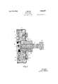
- Figure 1 is an outer side elevation ot' my improved wheel puller, portions thereof being broken away and interio parts being lshown in cross section.
- Figure 2 is a cross sectional view taken on the line 2+2 of Figure l.V
- Figure 3 is a partial plan view ot' Figure l.
- FIG. 1 is a circular metal block having a flat tace 2 provided with atcentral recess, or opening, 3 of sufficient diameter to receive the largest size of wheel hub, said block .on its other side being reduced to provide a centrally disposed sleeve 4 having a central threaded opening 5 extending completely therethrough and registering with the opening 3 centrally thereof, said threaded opening being adapted to receive an externally threaded pressure screw 6 adapted to be forced against the end of the axle in the
- the screw 6 is provided with a head 6a for the reception of a wrench or other tool.
- Radial slots 7 leading through the side wall of the opening 3 to the exterior of the block 1 are provided, which slots are sub* stantially T shaped in cross section, and are adapted to accommodate legs 8 of similar cross section which slide therein, the ilanges on corresponding sides of said legs respectively being provided with teeth 9.
- the inner ends of the legs 8 are concave as at 10 to correspond substantially to the exterior surface of the wheel hub and are provided with threads corresponding to the threads on the hub.
- the block l on the side on which the sleeve 4 is located is provided with circular openings 11 which extend inwardly to a point adjacent to the opposite ⁇ face of said block and register at theirone sides thereof with the sides of the openings 7 in which the teeth 9 of the legs S are located, there being one of such openings 11 between each pair of adjacent legs.
- Gears 12 are mounted in the respective openings 11 and regis- 60 ter with the teeth of the associated legs 8 so that on the rotation of said gears said legs will be moved towards, or away from, the central opening 3, according to the direction of travel of said gears.
- the gears 12 are 65 provided on their inner ends with reduced bearing shafts 13 which extend into suitable openings in the block 1 and constitute supports for the inner ends ot said gears. Said gears extend outwardly a considerable distance past the face of said block, as at 14, and are meshed with a circular gear wheel 15 which rotates around the sleeve 4c.
- a casing 16- encircles the sleeve 4 and encloses the corresponding face of the block and the edge thereof and such casing is secured in any desired manner, such as by the use of screws 17 threading into openings in the block.
- the outer ends of the gears 12 with the ex- 9 ception of one of said gears are supported by means of bolts 18 extending loosely through suitable openings in the casing 16 and threading into the ends of said gears, the remaining gear 12 having a rigid bearing 19, 85 or stem, extending through said casing past the headset the other bolts and having a head adapted for the reception of a wrench, or other tool 20, (said tool being shown in dotted line) so that rotary movementof said gear will he imparted simultaneously to all of the remaining gears.
- That portion of the edge of the block 1 adjacent to'thestem 19 is provided with notches 21 accessible through an opening 22 in the casing 16 adapted to be engaged by a pivoted pawl 23 carried by the tool 20 'so as to permit of locking-the gears againstrrotation when the legs 8 have been brought into engagement m with the wheel hub.
- the legs 8 are withdrawn to permit of the wheel hub entering the opening 3 and said legs are then brought into gripping engagement around said hub with the threads thereof registering with the threads on said hub by simply turning the stem 19 by means of the tool 20, which through the medium of the engaging teeth of the gears 12 and the legs 8 and the gear wheel 15, causes the legs to move inwardly, and the device is locked by simply inserting the pawl 23 in the desired notch 21 in the block 1.
- the screw 6' is then turned inwardly against the end of the axle until the wheel is removed.
- the present invention provides a simple tool adaptable to many purposes some of which are the removal of wheels, pulleys, gears, or bushings.
- a wheel puller comprising a block having a recess in one face thereof adapted to receive a wheel hub, said block having a threaded opening concentric with and of lesser diameter than said recess registering therewith through the opposite face of said block, a screw threading into said threaded opening, hub gripping elements slidable in radial slots in said block and adapted to enter said recess through the side wall thereof, rotary gears meshing with said hub gripping elements respectively and imparting longitudinal movement thereto, and a gear wheel common to all of said gears.
- a wheel puller comprising a block having a recess in one face thereof adapted to receive a wheel hub, radial slots extending from said recess outwardly, hub gripping elements slidable in said slots, the corresponding side edges of said elements having teeth therein, gears rotatably mounted between adjacent hub gripping elements at right angles to the longitudinal axis thereof and meshing with the toothed portions thereof respectively, a central gear wheel common to all of the afore- Said gears and on rotation imparting rotary movement to all of said bears simultaneously, and a screw entering said block through the other face thereof and extending into said recess.
- a wheel puller comprising a block having a recess in one face thereof adapted to receive a wheel hub, an internally threaded sleeve extending outwardly from the outer face of said block, the bore of said sleeve being of lesser diameter than that of said recess and registering therewith, a screw operating in said sleeve, slots extending radially through said block from said recess, legs slidable in said slots, said legs having their corresponding side edges provided with teeth, cylindrical gears rotatably journa-lled betweeen adjacent legs around said sleeve and meshing with the toothed portions thereof respectively, said gears projecting outwardly past the face of said block Von which said sleeve is located, a gear wheel mounted on said block and operating around said sleeve in mesh with the projecting portions of said gears, and a casing.
- a wheel puller comprising a block having a hub opening in one face thereof, a sleeve extending from the opposite face of said block and having a threaded opening of lesser diameter than said hub opening communicating with said hub opening in the diametrical centre thereof, a screw operating in said sleeve, a gear wheel rotatable around said sleeve on the face of said block, gears rotatably journalled in said block at spaced intervals around said gear wheel in right angular relation thereto and meshing therewith whereby rotary motion imparted to one of said gears will be communicated simultaneously to the remaining of said gears, said gears projecting inwardly beyond said gear wheel, hub engaging elements slidable longitudinally in radial slots through the side wall of said hub opening between adjacent pairs of said gears, said elements being substantially T shape in cross section and having theircorresponding side arms provided with teeth adapted to mesh with said inwardly projecting portions of said gears, said elements having their inner ends concaved and provided with threads adapted to
Landscapes
- Engineering & Computer Science (AREA)
- Mechanical Engineering (AREA)
- Gears, Cams (AREA)
Description
April 19, 1932. J. aAKos WHEEL FULLER Filed June 5;v 1930 2 Sheets-Sheet April 19, 1932.
Y J. BAKos WHEEL FULLER Filed June 5, 1950 2 Sheets-Sheet 2 Inventor:
'35 removal wheel.
Patented Apr. 19, 1932 UNITED STATES JOSEPH BAKOS, F MIMICO, 015]"13113'21O,v CANADA WHEEL PULLER Appication inea :rune 1930. serial' No. 459,361.
The invention relates to improvements in wheel pullers as described in the present specification and shown in the accompanying drawings that form a part of the saine.
The main objects of the invention are to provide a simple and efiicient wheel puller constructed of few parts and which is adaptable to all sizes of wheels.
VThe invention consists in the novel features i0 of construction, arrangements and combinations described in the present specification and more particularly pointed out in the claims for novelty following.
In the drawings Figure 1 is an outer side elevation ot' my improved wheel puller, portions thereof being broken away and interio parts being lshown in cross section.
Figure 2 is a cross sectional view taken on the line 2+2 of Figure l.V
Figure 3 is a partial plan view ot'Figure l.
Like numerals of reference indicate co-rrespending parts in the various figures.
Referring tothe drawings 1 is a circular metal block having a flat tace 2 provided with atcentral recess, or opening, 3 of sufficient diameter to receive the largest size of wheel hub, said block .on its other side being reduced to provide a centrally disposed sleeve 4 having a central threaded opening 5 extending completely therethrough and registering with the opening 3 centrally thereof, said threaded opening being adapted to receive an externally threaded pressure screw 6 adapted to be forced against the end of the axle in the The screw 6 is provided with a head 6a for the reception of a wrench or other tool.
Radial slots 7 leading through the side wall of the opening 3 to the exterior of the block 1 are provided, which slots are sub* stantially T shaped in cross section, and are adapted to accommodate legs 8 of similar cross section which slide therein, the ilanges on corresponding sides of said legs respectively being provided with teeth 9. The inner ends of the legs 8 are concave as at 10 to correspond substantially to the exterior surface of the wheel hub and are provided with threads corresponding to the threads on the hub.
The block l on the side on which the sleeve 4 is located is provided with circular openings 11 which extend inwardly to a point adjacent to the opposite `face of said block and register at theirone sides thereof with the sides of the openings 7 in which the teeth 9 of the legs S are located, there being one of such openings 11 between each pair of adjacent legs. Gears 12 are mounted in the respective openings 11 and regis- 60 ter with the teeth of the associated legs 8 so that on the rotation of said gears said legs will be moved towards, or away from, the central opening 3, according to the direction of travel of said gears. The gears 12 are 65 provided on their inner ends with reduced bearing shafts 13 which extend into suitable openings in the block 1 and constitute supports for the inner ends ot said gears. Said gears extend outwardly a considerable distance past the face of said block, as at 14, and are meshed with a circular gear wheel 15 which rotates around the sleeve 4c.
A casing 16- encircles the sleeve 4 and encloses the corresponding face of the block and the edge thereof and such casing is secured in any desired manner, such as by the use of screws 17 threading into openings in the block.
The outer ends of the gears 12 with the ex- 9 ception of one of said gears are supported by means of bolts 18 extending loosely through suitable openings in the casing 16 and threading into the ends of said gears, the remaining gear 12 having a rigid bearing 19, 85 or stem, extending through said casing past the headset the other bolts and having a head adapted for the reception of a wrench, or other tool 20, (said tool being shown in dotted line) so that rotary movementof said gear will he imparted simultaneously to all of the remaining gears. y
That portion of the edge of the block 1 adjacent to'thestem 19 is provided with notches 21 accessible through an opening 22 in the casing 16 adapted to be engaged by a pivoted pawl 23 carried by the tool 20 'so as to permit of locking-the gears againstrrotation when the legs 8 have been brought into engagement m with the wheel hub.
In the use of this invention the legs 8 are withdrawn to permit of the wheel hub entering the opening 3 and said legs are then brought into gripping engagement around said hub with the threads thereof registering with the threads on said hub by simply turning the stem 19 by means of the tool 20, which through the medium of the engaging teeth of the gears 12 and the legs 8 and the gear wheel 15, causes the legs to move inwardly, and the device is locked by simply inserting the pawl 23 in the desired notch 21 in the block 1. The screw 6' is then turned inwardly against the end of the axle until the wheel is removed.
The present invention provides a simple tool adaptable to many purposes some of which are the removal of wheels, pulleys, gears, or bushings.
Vhat I claim is 1. A wheel puller comprising a block having a recess in one face thereof adapted to receive a wheel hub, said block having a threaded opening concentric with and of lesser diameter than said recess registering therewith through the opposite face of said block, a screw threading into said threaded opening, hub gripping elements slidable in radial slots in said block and adapted to enter said recess through the side wall thereof, rotary gears meshing with said hub gripping elements respectively and imparting longitudinal movement thereto, and a gear wheel common to all of said gears.
2. A wheel puller comprising a block having a recess in one face thereof adapted to receive a wheel hub, radial slots extending from said recess outwardly, hub gripping elements slidable in said slots, the corresponding side edges of said elements having teeth therein, gears rotatably mounted between adjacent hub gripping elements at right angles to the longitudinal axis thereof and meshing with the toothed portions thereof respectively, a central gear wheel common to all of the afore- Said gears and on rotation imparting rotary movement to all of said bears simultaneously, and a screw entering said block through the other face thereof and extending into said recess.
3. A wheel puller comprising a block having a recess in one face thereof adapted to receive a wheel hub, an internally threaded sleeve extending outwardly from the outer face of said block, the bore of said sleeve being of lesser diameter than that of said recess and registering therewith, a screw operating in said sleeve, slots extending radially through said block from said recess, legs slidable in said slots, said legs having their corresponding side edges provided with teeth, cylindrical gears rotatably journa-lled betweeen adjacent legs around said sleeve and meshing with the toothed portions thereof respectively, said gears projecting outwardly past the face of said block Von which said sleeve is located, a gear wheel mounted on said block and operating around said sleeve in mesh with the projecting portions of said gears, and a casing.
4. A wheel puller comprising a block having a hub opening in one face thereof, a sleeve extending from the opposite face of said block and having a threaded opening of lesser diameter than said hub opening communicating with said hub opening in the diametrical centre thereof, a screw operating in said sleeve, a gear wheel rotatable around said sleeve on the face of said block, gears rotatably journalled in said block at spaced intervals around said gear wheel in right angular relation thereto and meshing therewith whereby rotary motion imparted to one of said gears will be communicated simultaneously to the remaining of said gears, said gears projecting inwardly beyond said gear wheel, hub engaging elements slidable longitudinally in radial slots through the side wall of said hub opening between adjacent pairs of said gears, said elements being substantially T shape in cross section and having theircorresponding side arms provided with teeth adapted to mesh with said inwardly projecting portions of said gears, said elements having their inner ends concaved and provided with threads adapted to register with the threads on said hub, a slotted casing encircling said sleeve and enclosing the corresponding face and the edge of said block, bearing elements extending loosely through said casing into said gears respectively, that portion of said block accessible through the slot in said casing being serrated, and a stem carried by one of said gears and extending through said casing in proximity to said slot therein.
Signed at Toronto, Ont. this 3rd day of June, 1980.
JOSEPH BAKOS.
Priority Applications (1)
| Application Number | Priority Date | Filing Date | Title |
|---|---|---|---|
| US459361A US1854877A (en) | 1930-06-05 | 1930-06-05 | Wheel puller |
Applications Claiming Priority (1)
| Application Number | Priority Date | Filing Date | Title |
|---|---|---|---|
| US459361A US1854877A (en) | 1930-06-05 | 1930-06-05 | Wheel puller |
Publications (1)
| Publication Number | Publication Date |
|---|---|
| US1854877A true US1854877A (en) | 1932-04-19 |
Family
ID=23824464
Family Applications (1)
| Application Number | Title | Priority Date | Filing Date |
|---|---|---|---|
| US459361A Expired - Lifetime US1854877A (en) | 1930-06-05 | 1930-06-05 | Wheel puller |
Country Status (1)
| Country | Link |
|---|---|
| US (1) | US1854877A (en) |
-
1930
- 1930-06-05 US US459361A patent/US1854877A/en not_active Expired - Lifetime
Similar Documents
| Publication | Publication Date | Title |
|---|---|---|
| US2520443A (en) | Planetary gear speed wrench | |
| US1744976A (en) | Screw or nut driving device for power-operated tools | |
| US2482387A (en) | Gear-operated double-socket wrench | |
| US2052534A (en) | Combination gear puller and press | |
| US2213379A (en) | Threading device | |
| US1431378A (en) | Wheel and gear puller | |
| US1854877A (en) | Wheel puller | |
| US977018A (en) | Key-extractor. | |
| US2077254A (en) | Gear puller | |
| US2227348A (en) | Flue bead cutting machine | |
| US1333532A (en) | Wrench | |
| US1589015A (en) | Puller | |
| US2275633A (en) | Dual wheel wrench | |
| US3580097A (en) | Screw and nut driver | |
| US2470179A (en) | Holding element for hub collars | |
| US2092598A (en) | Driver for rotary tools | |
| US1975984A (en) | Driving coupling for a rotary tool | |
| US2210742A (en) | Wrench adapter | |
| US2068021A (en) | Bushing extracting and inserting tool | |
| US2248147A (en) | Dimpling machine | |
| US1526502A (en) | Wrench | |
| US471765A (en) | Ratchet railroad-track wrench | |
| US1747689A (en) | Means for separating elements from shafts | |
| US1409554A (en) | Wrench | |
| US1846437A (en) | Pipe-swaging tool |