US1854863A - Reed converter - Google Patents
Reed converter Download PDFInfo
- Publication number
- US1854863A US1854863A US45967430A US1854863A US 1854863 A US1854863 A US 1854863A US 45967430 A US45967430 A US 45967430A US 1854863 A US1854863 A US 1854863A
- Authority
- US
- United States
- Prior art keywords
- current
- reed
- source
- contacts
- circuit
- Prior art date
- Legal status (The legal status is an assumption and is not a legal conclusion. Google has not performed a legal analysis and makes no representation as to the accuracy of the status listed.)
- Expired - Lifetime
Links
- 235000014676 Phragmites communis Nutrition 0.000 title description 70
- 238000004804 winding Methods 0.000 description 26
- 244000273256 Phragmites communis Species 0.000 description 15
- 239000004020 conductor Substances 0.000 description 9
- 150000001875 compounds Chemical class 0.000 description 7
- 230000000694 effects Effects 0.000 description 7
- 238000004891 communication Methods 0.000 description 6
- 230000000153 supplemental effect Effects 0.000 description 5
- 238000000034 method Methods 0.000 description 2
- FGRBYDKOBBBPOI-UHFFFAOYSA-N 10,10-dioxo-2-[4-(N-phenylanilino)phenyl]thioxanthen-9-one Chemical compound O=C1c2ccccc2S(=O)(=O)c2ccc(cc12)-c1ccc(cc1)N(c1ccccc1)c1ccccc1 FGRBYDKOBBBPOI-UHFFFAOYSA-N 0.000 description 1
- 229910000639 Spring steel Inorganic materials 0.000 description 1
- 229910000831 Steel Inorganic materials 0.000 description 1
- 230000001419 dependent effect Effects 0.000 description 1
- OYFJQPXVCSSHAI-QFPUQLAESA-N enalapril maleate Chemical compound OC(=O)\C=C/C(O)=O.C([C@@H](C(=O)OCC)N[C@@H](C)C(=O)N1[C@@H](CCC1)C(O)=O)CC1=CC=CC=C1 OYFJQPXVCSSHAI-QFPUQLAESA-N 0.000 description 1
- 239000012634 fragment Substances 0.000 description 1
- 230000001939 inductive effect Effects 0.000 description 1
- 230000003340 mental effect Effects 0.000 description 1
- 239000002184 metal Substances 0.000 description 1
- 239000003607 modifier Substances 0.000 description 1
- 230000000737 periodic effect Effects 0.000 description 1
- 230000002035 prolonged effect Effects 0.000 description 1
- 239000010959 steel Substances 0.000 description 1
- 230000001360 synchronised effect Effects 0.000 description 1
- 230000009466 transformation Effects 0.000 description 1
Images
Classifications
-
- H—ELECTRICITY
- H02—GENERATION; CONVERSION OR DISTRIBUTION OF ELECTRIC POWER
- H02M—APPARATUS FOR CONVERSION BETWEEN AC AND AC, BETWEEN AC AND DC, OR BETWEEN DC AND DC, AND FOR USE WITH MAINS OR SIMILAR POWER SUPPLY SYSTEMS; CONVERSION OF DC OR AC INPUT POWER INTO SURGE OUTPUT POWER; CONTROL OR REGULATION THEREOF
- H02M5/00—Conversion of AC power input into AC power output, e.g. for change of voltage, for change of frequency, for change of number of phases
- H02M5/02—Conversion of AC power input into AC power output, e.g. for change of voltage, for change of frequency, for change of number of phases without intermediate conversion into DC
- H02M5/32—Conversion of AC power input into AC power output, e.g. for change of voltage, for change of frequency, for change of number of phases without intermediate conversion into DC by dynamic converters
- H02M5/34—Conversion of AC power input into AC power output, e.g. for change of voltage, for change of frequency, for change of number of phases without intermediate conversion into DC by dynamic converters using mechanical contact-making and -breaking parts
Definitions
- My invention relates to electrical circuit controllers andl relates particularly to improvements in vibratile reed circuit controllers.
- My invention relates to that general type of vibratile reed circuit controllers disclosed in my prior Patent No. 1,646,662, dated October 25, 1927, the present application disclosing improvements to the method m and apparatus shown in my aforesaid prior patent.
- An object of my present invention is to provide lan improved controller for translating a periodically varying current into periodically varying' current impulses of a different effective frequency.
- Another object of my invention is to provide an improved reed operated circuit controller adapted to more continuously utilize the supplied current impulses in the translation of said impulses into current impulses which periodically vary at a relatively fractional rate.
- Another object of my invention is to provide Van improved synchronous reed con- I trolled current flow modifier.
- Another object of my invention is an improved electrical system. Another object of my invention is to pro- .l 3 vide a novel method of modifying electrical current flows. Other objects of my invention and the invention itself will become apparent by referbodiment of my invention illustrated more or less diagrammatically in the accompanying figures of drawings, wherein:
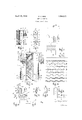
- F'ig. 1 is a side elevational view of an o electromagnetic reed controller employed in an embodiment of my 1nvention.
- Fig. 2 is an elevational view of the reed for the controller of Fig. l;
- Fig. 3 is a diagrammatic view of a system employing the controller of Fig. l;
- Fig. 4 is a side elevational viewr of a con troller' employing in combination the strncture of Figs. 1 and 2, together with an additional reed and circuit controlling contacts.
- Fig. 5 is a medial longitudinal section relaence to the following description of an emtively enlarged of a fragment of the controller of Fig. 4;
- Fig. 6 is an elevational view of a reed for the controller of Figs. 4 and 5.
- Fig. 7 is an elevational view of a supplemental. reed therefor.
- Fig. 8 is a diagrammatic view of an electrical system employing the controller of F'ig. 4;
- Fig. 9 is a diagrammatic view of the supplied current wave and successively disposed therebelow, impressed and resultant current waves resulting from the operation in electrical systems of the apparatus of the foregoing figures.
- FIG. 1 I show an electromagnet having a core terminating magnetically in laterally extending pole pieces 2 and 3 at its respective two ends.
- the pole piece 2 terminates in a pole flange 4 and the pole piece 3 terminating in a pair of inturned forks 5 and 6.
- a compound reed element comprising a pair of leaf springs 8 and 9 secured together by a pair of rivets 10 and an intermediate rivet 11 forming an electrical contact point as will later appear.
- the two springs are preferably of very thin spring steel strips and are relatively so superposed by end portions so that when secured together the eect of the spring 9 is to form a resilient extension for the spring 8 whose end 12 extends toward the free end of the spring 9 to a point approximately mid-way of the ends of said spring.
- the spring 8 is provided with a pair of perforations 13 adapted to admit the vShanks of rivets 14 projected therethrough, and through aligned perforations of a metallic block 15 and of the fork 6 of said electromagnet pole piece, whereby the conlipound reed 7 is rigidly mounted on said for
- the spring 9 carries an inertia weight element 16 which, inthe form of a looped strip of metal 17, embraces the spring 9y and to which there is rotatably secured an adjustable arm 18 pivoted to the free ends of the loop 17 by a rivet'19 securing the free ends of the loop and an end of the arm together in such a manner as to clamp the loop onto the spring and to form a pinion on which the arm 18 may frictionally rotate in order. to adjust- A ably disposed its free end more or less remote from the tip 20 of the spring 9.
- a contact screw 21 which is adjustablyscrew-threaded in an insulating bushing 2 2 carried by an end of the fork 5 of the pole piece 3.
- an alternating current transformer comprising a primary winding P and a secondary winding S of any desired transformation ratio, ⁇ su'ch as for instanceI 1 to 1.
- the secondary winding S is extended by circuit conductors 25 ⁇ to an desired electroresponsive devices adapta le for operation by the current derived from the mechanism and circuit described, such as the telephone polarized bells 26,-shown as being connected across the conductors 25, each in series with an appropriate electrical condenser 27.
- the winding of the electromagnet 1 is connected in serial. circuit with the source of alternating current 23 and the contacts -21 and 22, and the primary winding 1, in the embodim'ent illustrated, is shown as connected in multiple with .the Winding of theelectromagnet 1.
- the system of Fig. 3 operates as follows; Alternating current having the approximate wave form of that indicated at A 'in Fig. 8, being supplied from the source 23 to the winding of the electromagnet 1 through the contacts 21-11, Fig. 3, will energize the electromagnet to cause the end of the reed 7 to approach the pole piece flange 1, as indicated by the dotted lines 28, Fig. 1, at the' same time effecting breaking of the circuit byseparation of the contacts -21--11. The contacts being broken, the reed by the power Of S l and 9 and mechanical engagement on t own inherent resiliency will retract to again close the contacts with the foregoing result repeated.
- each forward excursion of the reed will be caused to take just twice as long as each rearward excursion thereof.
- the current impulses through the electromagnet 1 are of alternate polarity and spaced from the next succeeding impulses of current by a full cycle of omitted impulses of alternating current indicated by dotted lines at b.
- the solid line impulses a and a of successively opposite polarity passing through the electromagnet 1 also pass through the primary winding P of the transformer 24 with the result that an alternating current is supplied by the .secondary Winding thereof having a periodicity one-third that of the periodiclty of current supplies by the source 23 as shown by the compound reed of my present invention are similar to those previously described in my prior .Patent No. 1,646,662, dated October 25, 1927, and to which reference may be had.
- the reenforcing portion of the spring l8, overlapping the spring 9 causes a resistance to be resiliently applied to retractive movements ofthe spring 9, and particularly this is true when the contact screw 21engages the Contact 11 affixed' to the reed 7 at a point spaced from its support 6.
- the overlapping pori tion of the spring 8 has no such function and the; spring 9 and the supporting portion of the spring 8 swings freely. mwardl in a4 manner similar to that which woul occur, were the springs 8 and 9 one continual spring with no overlapping portion.
- the arm 8 of the element 16 In effecting vibrationv of the compound reed at a rate which is exactly two-thirds that 0f the periodicity of the supplied alternating current, the arm 8 of the element 16 ma .be adjusted to varying positionsb rotating it on the pin 19 until its perio icity corresponds to the fractional periodicity of the alternating current desired.
- the tuning of the compound reed is to be accomplished with a View to the frequency of alternating current desired to be obtained by the operation of the system and that the reed vibration rate above given is that which would be required to be had where it is desired to obtain an alternating current whose periodicity is one-third that of the periodicity of current from the source, as described herein.
- An elongated main reed 32 and a short contact-carrying supplemental reed 33 are supported by an end of each, in relatively superposed relation on the arm 30 being clamped thereto by a plate 34 and rivets 35 projected through aligned apertures of said plate, said superposed reeds and said a-rm 30.
- the main and supple- 'mental reeds, per se, are respectively illusis shown provided in the supplemental reed 33 for the reception of the reduced neck 38, Fig. 5, of an electrical contact element 39 in lthe form of a rivet and having a contact portion projected from a flat side of the supplemental reed.
- an enlarged aperture 40, Figs. 5 and 6, isrprovided through which the projecting portion of the contact 39 may extend for engagement by the contact point of the fixed contact screw 41, which is adj ustably mounted in the insulating block or bushing 43 carried by the arm 31.
- the supplemental reed 33 being substantial-ly shorter, less than one-half the length, than the reed 32, terminates at a point 44 which lies but slightly beyond the contact 39 carried by it and being disposed on the outer side of the main reed 32, and engageable therewith on all outward excursions, such as indicated at 45 of tlie reed 32, restrains the main reed in outward movements, that is, when moving in directions away from the pole tip 2".
- the 'presence of the reed33 at first 4 accelerates the ⁇ inward movement 'toward the position 46 yof the reed k32 and the inward swing of the reed,32, like the inwardswing of the reed 9 ⁇ is of much greater'amplitude than the outward swing, as at 29, referring again to the reed 9.
- Fig. 8 The electrical circuit preferably employed for the embodiment of Fig. 4 is illustrated in Fig. 8 and by reference thereto, it will be noted that current low through the electro magnet 1 is directly controlled by the contacts 1121, whereas the contacts 39 and 41 are employed in the circuit merely to control the flow of current through one of two primary Iwindings P-2 of a transformer T having a secondary winding S and a second primary winding P-1.
- the said second primary winding is connected across the terminals of the electroinagnet 1 and therefore both the electro-magnet and the primary winding P-l is always exposed to the same varying electro-motive force.
- the two contact sets may be differentiated in that the contact set 11-21 is both a motor controlling contact set and a currentcommutating contact set for the primary winding P-1,whereas the contact set 39-41 is intended principally for the purpose of cominutating the current through the primary winding P-2.
- pair of condensers 47 and 48 may be employed connected as shown in the circuit of Fig. 8 to more conipletely eliminate the tendency toward sparking, which may occur at the two sets of contacts where precise adjustments thereof and of the adjust-able weighting elements 18 and 18 for the reeds 9 and 32 respectively are not had.
- the electro-magnet coil 1 is that of the apparatus of Fig. 4, as are also the reeds 9, 32,
- Vand 33 and the respective contact sets therefor.
- the transformer is provided with two like primary windings joined together at an end of each from which an electrical circuit conductor 49 extends to a pole of the source 23 of alternating current.
- the other pole of the source of current leads by a conductor 50 to branching circuit conductors which are electrical-ly connected to the reeds 8, 9 and 33, the carried contacts of which are intermittently engaged, as before described by the fixed contacts 21 and 41, respectively.
- the current impulses which pass from the generator 23 through the contacts 11-21, to the transformer having the primary winding P, are those shown in solid lines at a and b at B, Fig. 9, those at a being, we will assume, positive impulses, and those at b being assumed to be negativeimpulses. It is noted that the posit-,ive and negative impulses are alternated with respect to time, which is taken as running from left to right, Fig. 9, and that between each positive and each negativesuccessive impulse, there is omitted a complete cycle comprising two immediately adjacent negative and positive waves.
- the impressed current, shown at D, provided by the contacts 39-41' may be consideredas being reversed in polarity, when supplied'to the transformer having the secondary winding S, with respect to such secondary winding, since current flow throughlthecon-l tacts 39-41 passes through the primary winding 13 2 (see D) in a direction whic is exactly opposite to the direction of flow of impulses through the contacts 11-21 (see B), so that when considering such impressed current in connection with the impressed current through the primary winding .P-1, and
- the wave form of the resulting current through the winding P--2 is probably much E, respectively, the impressed wave forms of B and E being combined, provide a wave, as shown at G, wherein three immediately connected positive impulses are immediately succeeded by three immediately connected negative impulses ad infinitum.V Also the combination of the resultant wave forms C and F provides a wave which may be more or less like that shown at H, although this showing is exaggerated to accentuate the triple ripples at the crest of each positive and negative wave.
- the wave H is that which is delivered by the secondary winding S, Fig. 8, to the electro-responsive devices such as telephone bells 26', which are serially connected across circuit conductors leading from the said secondary winding, each bell preferably being a serieswith an associated condenser 27 in accordance with-common standard practice.
- a source of current a transformer, a air of primar transformer coils and a secon a coil there or, a pair o f vibratile reeds associated therewith, current commutating means foreach reed operable thereb electro-magnetic means for actuating sai reeds, both of said reeds ⁇ tuned to vibrate at the same periodic rate, each of said commutating means under the control of a different reed adapted to complete a circuit to a different one of said primary coils, during a fraction of the period of each complete vibration which is lli different, in point of time, theny the period ofcircuit closure effected by the other com ⁇ mutating means, during the remaining fraction of' said period.
- a source of electrical alternating current a pair of reeds each tuned to vibrate synchronously with the impulses of current from said source, a current supply circuit, a set of electrical contacts operable by each reed synchronously therewith independently controlling the flow of current from the source to the supply circuit, each of said reeds periodically closing a different circuit from the source to the supply circuit during alternate successive periods.
- a source of electrical alternating current a pair of reeds each tuned to vibrate synchronously with the impulses of current from said source, a current supply circuit, a set of electrical contacts operable by each reed synchronously therewith independently controlling the flow of current from the source to the supply circuit, each -of said reeds periodically modifying the current flowing from the source to the supply circuit during alternate successive periods.
- a source of periodically variable current a pair of reeds adapted to vibrate synchronously with the impulses of current from said source, means receiving current from said source eecting vibration of said reeds, current commutating means under the control of both said reeds, a discharge circuit and an electrical circuit including said source and said commutating means for supplying modiiied current impulses to said discharge circuit.
Landscapes
- Engineering & Computer Science (AREA)
- Power Engineering (AREA)
- Electromagnets (AREA)
Description
WA C. ROE
REED CONVERTER Filed June 7, 1930 Patented Apr. 19, 1932 UNITED STATES l.PATENT OFFICE WILLIAM C. ROE, F ELYRIA, OHIO, .ASSIGNOB TO TELKOR, INC., OF ELYRIA, OHIO, A
CORPORATION OHIO REED CONVERTER Application mea :une 7, 1930. serial No. 459,674.
My invention relates to electrical circuit controllers andl relates particularly to improvements in vibratile reed circuit controllers.
51 My invention relates to that general type of vibratile reed circuit controllers disclosed in my prior Patent No. 1,646,662, dated October 25, 1927, the present application disclosing improvements to the method m and apparatus shown in my aforesaid prior patent. An object of my present invention is to provide lan improved controller for translating a periodically varying current into periodically varying' current impulses of a different effective frequency.
Another object of my invention is to provide an improved reed operated circuit controller adapted to more continuously utilize the supplied current impulses in the translation of said impulses into current impulses which periodically vary at a relatively fractional rate.
Another object of my invention is to provide Van improved synchronous reed con- I trolled current flow modifier.
Another object of my invention is an improved electrical system. Another object of my invention is to pro- .l 3 vide a novel method of modifying electrical current flows. Other objects of my invention and the invention itself will become apparent by referbodiment of my invention illustrated more or less diagrammatically in the accompanying figures of drawings, wherein:
F'ig. 1 is a side elevational view of an o electromagnetic reed controller employed in an embodiment of my 1nvention. Fig. 2 is an elevational view of the reed for the controller of Fig. l;
Fig. 3 is a diagrammatic view of a system employing the controller of Fig. l;
Fig. 4 is a side elevational viewr of a con troller' employing in combination the strncture of Figs. 1 and 2, together with an additional reed and circuit controlling contacts. Fig. 5 is a medial longitudinal section relaence to the following description of an emtively enlarged of a fragment of the controller of Fig. 4;
Fig. 6 is an elevational view of a reed for the controller of Figs. 4 and 5.
Fig. 7 is an elevational view of a supplemental. reed therefor.
Fig. 8 is a diagrammatic view of an electrical system employing the controller of F'ig. 4;
Fig. 9 is a diagrammatic view of the supplied current wave and successively disposed therebelow, impressed and resultant current waves resulting from the operation in electrical systems of the apparatus of the foregoing figures.
Referring now first to the apparatus of Figs. 1 and` 2 and the system of Fig. 3, in which the said apparatus is employed, at 1 I show an electromagnet having a core terminating magnetically in laterally extending pole pieces 2 and 3 at its respective two ends.
The pole piece 2 terminates in a pole flange 4 and the pole piece 3 terminating in a pair of inturned forks 5 and 6.
At 7 I show a compound reed element comprising a pair of leaf springs 8 and 9 secured together by a pair of rivets 10 and an intermediate rivet 11 forming an electrical contact point as will later appear. The two springs are preferably of very thin spring steel strips and are relatively so superposed by end portions so that when secured together the eect of the spring 9 is to form a resilient extension for the spring 8 whose end 12 extends toward the free end of the spring 9 to a point approximately mid-way of the ends of said spring. The spring 8 is provided with a pair of perforations 13 adapted to admit the vShanks of rivets 14 projected therethrough, and through aligned perforations of a metallic block 15 and of the fork 6 of said electromagnet pole piece, whereby the conlipound reed 7 is rigidly mounted on said for The spring 9 carries an inertia weight element 16 which, inthe form of a looped strip of metal 17, embraces the spring 9y and to which there is rotatably secured an adjustable arm 18 pivoted to the free ends of the loop 17 by a rivet'19 securing the free ends of the loop and an end of the arm together in such a manner as to clamp the loop onto the spring and to form a pinion on which the arm 18 may frictionally rotate in order. to adjust- A ably disposed its free end more or less remote from the tip 20 of the spring 9.
The reed as mounted on the-electromagnet structure of Fig. 1 is disposed with the spring 9 innermost, that is, towards the electromagnet 1, and the contact 11, heretofore referred to as a rivet, projects outwardly to engage the contacting end of a contact screw 21 which is adjustablyscrew-threaded in an insulating bushing 2 2 carried by an end of the fork 5 of the pole piece 3.
When the screw 21 is turned in the bushing to advance its point into contact with the contact 11, an electrical circuit is completed between said screw and said contact and when the electrical circuit' of Fig. 3 is complete, including said contact screw 21 and contact 11, the compound reed is lthrown into vibration under the control of the contacts 11-21 at a rate dependent upon the inherent properties of the reed, the electrical and mechanical effect of the engagement of the contacts and the strength of the magnetic field in which the steel compound reed is oscillated, but under the dominant control of the impulses of electrical currentsupplies from af source such as the alternating' current generator 23 over t-he circuit conductors, as illustrated inFig. 3, the circuit of which will now be explained.
Referring now particularly to Fig. 3, at 24 an alternating current transformer is illustrated comprising a primary winding P and a secondary winding S of any desired transformation ratio,` su'ch as for instanceI 1 to 1. The secondary winding S is extended by circuit conductors 25` to an desired electroresponsive devices adapta le for operation by the current derived from the mechanism and circuit described, such as the telephone polarized bells 26,-shown as being connected across the conductors 25, each in series with an appropriate electrical condenser 27.
The winding of the electromagnet 1 is connected in serial. circuit with the source of alternating current 23 and the contacts -21 and 22, and the primary winding 1, in the embodim'ent illustrated, is shown as connected in multiple with .the Winding of theelectromagnet 1.
The system of Fig. 3 operates as follows; Alternating current having the approximate wave form of that indicated at A 'in Fig. 8, being supplied from the source 23 to the winding of the electromagnet 1 through the contacts 21-11, Fig. 3, will energize the electromagnet to cause the end of the reed 7 to approach the pole piece flange 1, as indicated by the dotted lines 28, Fig. 1, at the' same time effecting breaking of the circuit byseparation of the contacts -21--11. The contacts being broken, the reed by the power Of S l and 9 and mechanical engagement on t own inherent resiliency will retract to again close the contacts with the foregoing result repeated.
lVhen so oscillated, the reed constructed as illustrated in Figs. l and 2 will oscillate within the limits relatively substantially as shown by the dotted lines 28 and 29 to periodically make and break the contacts 21-11. lDue to the compound natureof the reed, the relative positioning of its e back stroke between the contact 11, carried by the reed and the fixed contact 21, the reed will take a longer excursion toward the pole flange 4 than in the opposite direction, and by suitable adjustment of the screw 21 while parts 8.
the reed is vibrated, each forward excursion of the reed will be caused to take just twice as long as each rearward excursion thereof. When this result is obtained, the fact will be visually evident'to the one making the adjustment by noting that at such time the substantially complete absence of electrical sparking at the contacts.
When this condition is secured, it is found that the reed is vibrating by impulses of current taken from the wave such as shown at A, Fig. 9, and indicated in solid lines by the lportions thereof shown at a', Fig. 9. In
other words, as shown at B, the current impulses through the electromagnet 1 are of alternate polarity and spaced from the next succeeding impulses of current by a full cycle of omitted impulses of alternating current indicated by dotted lines at b. The solid line impulses a and a of successively opposite polarity passing through the electromagnet 1 also pass through the primary winding P of the transformer 24 with the result that an alternating current is supplied by the .secondary Winding thereof having a periodicity one-third that of the periodiclty of current supplies by the source 23 as shown by the compound reed of my present invention are similar to those previously described in my prior .Patent No. 1,646,662, dated October 25, 1927, and to which reference may be had.
In the appara-tus of F 1, the reenforcing portion of the spring l8, overlapping the spring 9 causes a resistance to be resiliently applied to retractive movements ofthe spring 9, and particularly this is true when the contact screw 21engages the Contact 11 affixed' to the reed 7 at a point spaced from its support 6. On the forward excursion toward the position 28, however, the overlapping pori tion of the spring 8 has no such function and the; spring 9 and the supporting portion of the spring 8 swings freely. mwardl in a4 manner similar to that which woul occur, were the springs 8 and 9 one continual spring with no overlapping portion.
In effecting vibrationv of the compound reed at a rate which is exactly two-thirds that 0f the periodicity of the supplied alternating current, the arm 8 of the element 16 ma .be adjusted to varying positionsb rotating it on the pin 19 until its perio icity corresponds to the fractional periodicity of the alternating current desired.
It will be understood that the tuning of the compound reed is to be accomplished with a View to the frequency of alternating current desired to be obtained by the operation of the system and that the reed vibration rate above given is that which would be required to be had where it is desired to obtain an alternating current whose periodicity is one-third that of the periodicity of current from the source, as described herein.
In the embodiment of my invention illustrated in Fig. 4, the apparatus shown to the right of the longitudinal middle line affis like that previously shown andy/described in connection with Figs. 1, 2, 3 and 9, and therefore this art of the apparatus of Fig. 4 will be re erred to but briefly in connection with the description of the operation of the apparatus shown to the left of the medial line of Fig. 4, wherein the pole pieces 2 and 3 of Fig. 1 are integrally prolonged toward the left to provide the pole tip 2 and the pole piece 3' bifurcated at its end to provide the reed supporting arm 30 and the fixed contact supporting arm 31. An elongated main reed 32 and a short contact-carrying supplemental reed 33 are supported by an end of each, in relatively superposed relation on the arm 30 being clamped thereto by a plate 34 and rivets 35 projected through aligned apertures of said plate, said superposed reeds and said a-rm 30. The main and supple- 'mental reeds, per se, are respectively illusis shown provided in the supplemental reed 33 for the reception of the reduced neck 38, Fig. 5, of an electrical contact element 39 in lthe form of a rivet and having a contact portion projected from a flat side of the supplemental reed.
Also, an enlarged aperture 40, Figs. 5 and 6, isrprovided through which the projecting portion of the contact 39 may extend for engagement by the contact point of the fixed contact screw 41, which is adj ustably mounted in the insulating block or bushing 43 carried by the arm 31.
The supplemental reed 33 being substantial-ly shorter, less than one-half the length, than the reed 32, terminates at a point 44 which lies but slightly beyond the contact 39 carried by it and being disposed on the outer side of the main reed 32, and engageable therewith on all outward excursions, such as indicated at 45 of tlie reed 32, restrains the main reed in outward movements, that is, when moving in directions away from the pole tip 2".
However, the 'presence of the reed33 at first 4 accelerates the `inward movement 'toward the position 46 yof the reed k32 and the inward swing of the reed,32, like the inwardswing of the reed 9 `is of much greater'amplitude than the outward swing, as at 29, referring again to the reed 9.
It is to be noted, however, that the positioning and relationship of the contacts 39-41 is diii'erent from that of -the contacts 11-21, and the adjustment ofthe contact screws is previously made so that when there is engagementbetwec-n the-contacts 11 and 21, the contacts 40 and 39 are. disengaged and the contrary is also true, namely, that upon .engagement of the contacts 39 and .41, there will be disengagement of the contacts 11 and 21.
The electrical circuit preferably employed for the embodiment of Fig. 4 is illustrated in Fig. 8 and by reference thereto, it will be noted that current low through the electro magnet 1 is directly controlled by the contacts 1121, whereas the contacts 39 and 41 are employed in the circuit merely to control the flow of current through one of two primary Iwindings P-2 of a transformer T having a secondary winding S and a second primary winding P-1.
The said second primary winding is connected across the terminals of the electroinagnet 1 and therefore both the electro-magnet and the primary winding P-l is always exposed to the same varying electro-motive force. The two contact sets may be differentiated in that the contact set 11-21 is both a motor controlling contact set and a currentcommutating contact set for the primary winding P-1,whereas the contact set 39-41 is intended principally for the purpose of cominutating the current through the primary winding P-2. pair of condensers 47 and 48 may be employed connected as shown in the circuit of Fig. 8 to more conipletely eliminate the tendency toward sparking, which may occur at the two sets of contacts where precise adjustments thereof and of the adjust- able weighting elements 18 and 18 for the reeds 9 and 32 respectively are not had.
ln the electrical system of Fig. 8, the alternating current generator is shown at 23. The electro-magnet coil 1 is that of the apparatus of Fig. 4, as are also the reeds 9, 32,
- When the respective circuits served by these contacts are closed thereby, alternately, as before related, current is alternatel directed through the primary windings -1 and P2 in the opposite directions, as indicated by the arrows shown between the pri.
there being shown both impressed and resultant current waves and of these the upper- 'most wave A will be assumed to be the current wave ordinarily supplied from a generator, 'such as that shown at 23 when a xed loadl v is applied to the generator. It also represents ythe current Wave supplied from the generator 23 to the electrical system illustrated in Fig. 8.
s The current impulses which pass from the generator 23 through the contacts 11-21, to the transformer having the primary winding P, are those shown in solid lines at a and b at B, Fig. 9, those at a being, we will assume, positive impulses, and those at b being assumed to be negativeimpulses. It is noted that the posit-,ive and negative impulses are alternated with respect to time, which is taken as running from left to right, Fig. 9, and that between each positive and each negativesuccessive impulse, there is omitted a complete cycle comprising two immediately adjacent negative and positive waves.
The effect of periodically omitting fa cycle ofcurrent on the wave form of resultant current is 'approximately diagrammatically shown at C, the magnetic lag in the transformer of the system and the inductance of :between each'cycle of impressed current suppliedl through the contacts 39-41, as shown at D, there is omitted. successively, negative `impulses b and positive impulses a at the times as shown by theimpulses b and a at B when such impulses are permitted to flow by the contacts 11-21. j The impressed current, shown at D, provided by the contacts 39-41'may be consideredas being reversed in polarity, when supplied'to the transformer having the secondary winding S, with respect to such secondary winding, since current flow throughlthecon-l tacts 39-41 passes through the primary winding 13 2 (see D) in a direction whic is exactly opposite to the direction of flow of impulses through the contacts 11-21 (see B), so that when considering such impressed current in connection with the impressed current through the primary winding .P-1, and
both in relation to the effect on the secondary` winding S, it is easier to consider the im'- pulses as being in the reversed direction, as shown by E.
By analogy to the curve shown at C, relative to the impressed current, as shown at B, the wave form of the resulting current through the winding P--2 is probably much E, respectively, the impressed wave forms of B and E being combined, provide a wave, as shown at G, wherein three immediately connected positive impulses are immediately succeeded by three immediately connected negative impulses ad infinitum.V Also the combination of the resultant wave forms C and F provides a wave which may be more or less like that shown at H, although this showing is exaggerated to accentuate the triple ripples at the crest of each positive and negative wave.
The wave H is that which is delivered by the secondary winding S, Fig. 8, to the electro-responsive devices such as telephone bells 26', which are serially connected across circuit conductors leading from the said secondary winding, each bell preferably being a serieswith an associated condenser 27 in accordance with-common standard practice.
Having thus described' my invention in certain embodiments thereof, I am aware that numerous and extensive departures may be made from the embodiments herein illustrated and described, but without departing from the spirit of my invention.
I claim: 1. In an electrical system, the combination with a source of current, a transformer, a air of primar transformer coils and a secon a coil there or, a pair o f vibratile reeds associated therewith, current commutating means foreach reed operable thereb electro-magnetic means for actuating sai reeds, both of said reeds `tuned to vibrate at the same periodic rate, each of said commutating means under the control of a different reed adapted to complete a circuit to a different one of said primary coils, during a fraction of the period of each complete vibration which is lli different, in point of time, theny the period ofcircuit closure effected by the other com` mutating means, during the remaining fraction of' said period.
2. In an electrical system, the combination with a source of alternating current, a transformer having a secondary coil and a pair of primary coils inductively related thereto, a current commutator and electrical circuit conductors independently associated with each of said primary coils adapted to communicate current fromthe source to the associated primary coil to effect communication of impulses of current therethrough and vibratile reed means including an electromagnet receiving current from said source, an .a tuned reed mechanism, for controlling the operation of the two commutators to effect communication of current from the source through one of said commutators to its associated primary coil for a fractional part of each alternating current Wave and communication of current by the other commutator to its associated primary coil for the rest of each said current wave.
3. In an electrical system, the combination with a source of alternating current, a transformer havingV a secondary coil and a pair of primary coils inductively related thereto, a current commutator and electrical circuit conductors independently associated with each of said primary coils adapted to communicate current from the source to the associated primary coil to effect communication of impulses of current therethrough and vibratile reed means including an electromagnet receiving current from said source, and a tuned reed mechanism, for controlling the operation of the two commutators to effect communication of current from the source through one of said commutators to its associated primary coil for a fractional part of each alternating current wave and communication of current by the other commutator to its associated primary coil for the rest of each said current wave, one of said primary coils being reversed relative to its inductive effect communicated to the secondary coil by current communicated thereto from said source, relative to that communicated to the other coil therefrom.
4. In an electrical system, a source of alternating'current, a` primary circuit, a sec- 'ondary circuit, a pair of commutators each in a lseparate branch of the primary circuit both leading from the source, tuned reed means to alternately cause said commutators to periodically divert current from the source to said branches, and means to relatively oppositel communicate with respect to direction o current low the commutated current from the branches to the secondary circuit.
5. In an electrical system, a source of electrical alternating current, a pair of reeds each tuned to vibrate synchronously with the impulses of current from said source, a current supply circuit,a set of electrical contacts operable by each reed synchronously therewith independently controlling the flow of current from the source to the supply circuit, each of said reeds periodically closing a different circuit from the source to the supply circuit during alternate successive periods.
6. In an electrical system, a source of electrical alternating current, a pair of reeds each tuned to vibrate synchronously with the impulses of current from said source, a current supply circuit, a set of electrical contacts operable by each reed synchronously therewith independently controlling the flow of current from the source to the supply circuit, each -of said reeds periodically modifying the current flowing from the source to the supply circuit during alternate successive periods.
7. In an electrical system, a source of periodically variable current, a pair of reeds adapted to vibrate synchronously with the impulses of current from said source, means receiving current from said source eecting vibration of said reeds, current commutating means under the control of both said reeds, a discharge circuit and an electrical circuit including said source and said commutating means for supplying modiiied current impulses to said discharge circuit.
In testimony whereof I hereunto affix my signature this 10th day of A ril, 1930.
WILLI M C. ROE.
lOl)
Priority Applications (2)
| Application Number | Priority Date | Filing Date | Title |
|---|---|---|---|
| US45967430 US1854863A (en) | 1930-06-07 | 1930-06-07 | Reed converter |
| US561614A US1919041A (en) | 1930-06-07 | 1931-09-08 | Reed mechanism |
Applications Claiming Priority (1)
| Application Number | Priority Date | Filing Date | Title |
|---|---|---|---|
| US45967430 US1854863A (en) | 1930-06-07 | 1930-06-07 | Reed converter |
Publications (1)
| Publication Number | Publication Date |
|---|---|
| US1854863A true US1854863A (en) | 1932-04-19 |
Family
ID=23825727
Family Applications (1)
| Application Number | Title | Priority Date | Filing Date |
|---|---|---|---|
| US45967430 Expired - Lifetime US1854863A (en) | 1930-06-07 | 1930-06-07 | Reed converter |
Country Status (1)
| Country | Link |
|---|---|
| US (1) | US1854863A (en) |
Cited By (4)
| Publication number | Priority date | Publication date | Assignee | Title |
|---|---|---|---|---|
| US2444044A (en) * | 1941-09-13 | 1948-06-29 | Automatic Elect Lab | Impulse generator |
| US2489926A (en) * | 1947-12-23 | 1949-11-29 | Bell Telephone Labor Inc | Pulsing circuit |
| US2603769A (en) * | 1949-10-12 | 1952-07-15 | Telkor Inc | Alternating current frequency converter |
| US2618717A (en) * | 1945-08-01 | 1952-11-18 | Hakanssons Ind Ab | Oscillating contact device for periodical variation of electric current conditions |
-
1930
- 1930-06-07 US US45967430 patent/US1854863A/en not_active Expired - Lifetime
Cited By (4)
| Publication number | Priority date | Publication date | Assignee | Title |
|---|---|---|---|---|
| US2444044A (en) * | 1941-09-13 | 1948-06-29 | Automatic Elect Lab | Impulse generator |
| US2618717A (en) * | 1945-08-01 | 1952-11-18 | Hakanssons Ind Ab | Oscillating contact device for periodical variation of electric current conditions |
| US2489926A (en) * | 1947-12-23 | 1949-11-29 | Bell Telephone Labor Inc | Pulsing circuit |
| US2603769A (en) * | 1949-10-12 | 1952-07-15 | Telkor Inc | Alternating current frequency converter |
Similar Documents
| Publication | Publication Date | Title |
|---|---|---|
| US1854863A (en) | Reed converter | |
| US1676979A (en) | Vibratory converter | |
| US2113762A (en) | Vibrator transformer and rectifier | |
| US2135843A (en) | Magnetogenerator | |
| US2372966A (en) | Electric translating apparatus | |
| US1919041A (en) | Reed mechanism | |
| US1842595A (en) | Electromagnetic device | |
| US2292630A (en) | Distant control vibrator currentconverting system | |
| US2410974A (en) | Vibrator circuit | |
| US2439107A (en) | Vibrator circuit | |
| US1883773A (en) | Electromagnetic relay | |
| US2020681A (en) | Vibrator and operating circuit therefor | |
| US1871904A (en) | Frequency converter | |
| US1184233A (en) | Rectifying apparatus for electric currents. | |
| US1994635A (en) | Converter | |
| US2872672A (en) | Telephone ringer and the like | |
| US1717475A (en) | Alternating-current relay | |
| US1019608A (en) | Vibrating rectifier. | |
| US1271732A (en) | Current-modifier. | |
| US1834447A (en) | Electrical apparatus | |
| US2472367A (en) | Electrically operated vibrator apparatus | |
| US2603769A (en) | Alternating current frequency converter | |
| US580988A (en) | Daniel mcfarlan moore | |
| US1580359A (en) | Radio receiving system | |
| US1146954A (en) | Electric regulator. |