US185485A - Improvement in screw-propellers - Google Patents
Improvement in screw-propellers Download PDFInfo
- Publication number
- US185485A US185485A US185485DA US185485A US 185485 A US185485 A US 185485A US 185485D A US185485D A US 185485DA US 185485 A US185485 A US 185485A
- Authority
- US
- United States
- Prior art keywords
- blade
- screw
- propeller
- blades
- propellers
- Prior art date
- Legal status (The legal status is an assumption and is not a legal conclusion. Google has not performed a legal analysis and makes no representation as to the accuracy of the status listed.)
- Expired - Lifetime
Links
- XLYOFNOQVPJJNP-UHFFFAOYSA-N water Substances O XLYOFNOQVPJJNP-UHFFFAOYSA-N 0.000 description 5
- 238000010276 construction Methods 0.000 description 2
- 230000015572 biosynthetic process Effects 0.000 description 1
- 230000000052 comparative effect Effects 0.000 description 1
- 238000010586 diagram Methods 0.000 description 1
- 230000000694 effects Effects 0.000 description 1
- 230000002452 interceptive effect Effects 0.000 description 1
- 239000000463 material Substances 0.000 description 1
Images
Classifications
-
- F—MECHANICAL ENGINEERING; LIGHTING; HEATING; WEAPONS; BLASTING
- F04—POSITIVE - DISPLACEMENT MACHINES FOR LIQUIDS; PUMPS FOR LIQUIDS OR ELASTIC FLUIDS
- F04D—NON-POSITIVE-DISPLACEMENT PUMPS
- F04D29/00—Details, component parts, or accessories
- F04D29/66—Combating cavitation, whirls, noise, vibration or the like; Balancing
- F04D29/661—Combating cavitation, whirls, noise, vibration or the like; Balancing especially adapted for elastic fluid pumps
- F04D29/666—Combating cavitation, whirls, noise, vibration or the like; Balancing especially adapted for elastic fluid pumps by means of rotor construction or layout, e.g. unequal distribution of blades or vanes
Definitions
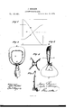
- Figure 1 is a diagram in illustration of the construction of a twobladed propeller in accordance with my invention.
- Figs. 2 and 3 are elevations of the propeller in different directions, oblique to the axis thereof.
- Fig. 4 is a section in a plane parallel with the axis on the line a; as; Fig. 5,
- Both blades B and 0 should be constructed with openings b 0, through them at their junction with the hub. These openings not merely provide for a ready clearance of dead-water about or around the hub, or prevent the formation of dead-water at such part, but, so far as the one, b, of them in the blade B of larger radius is concerned, the same provides for said blade working during the rotation of the propeller outside of or beyond the course described by the outer edge of the smaller blade 0, whereby there is no material interference of one blade with the action of the other, or liability of one blade to work in the currents or votexes formed by the different blades.
- Fig. l in which the line d represents the axis of the propeller, the line 0 the pitch-line of the blade B, of greater radius, and the linef the pitchline of the blade 0, of lesser radius, it will be seen that, While both blades are of the same pitch, they present different angles to the water, by reason of their different lengths or radiuses, the smaller blade presenting the greatest angle.
- the arms g g of the blade B should be of a twisted construction, to prevent them dragging, and to give them a paddle-like action in or on the edges of the current produced by the blade 0.
- the blade B also should be set inclining on the face, as at h, Fig. 5, to throw the water toward the outer edge of said blade, where it is acted upon with the best effect, while the other blade 0 should be free from any such inclination on its face.
- a screw-propeller constructed with two or more blades of different radiuses and different areas relatively with each other, and with openings through them, substantially as and for the purposes herein set forth.
Landscapes
- Engineering & Computer Science (AREA)
- Mechanical Engineering (AREA)
- General Engineering & Computer Science (AREA)
- Structures Of Non-Positive Displacement Pumps (AREA)
Description
J. BURSON.
SCREW-PROPELLER.
Nc.185,485. Patented Dec. 19, 1876.
Fly!
THE GRAPHIC CO N.Y.
UNITED STATES PATENT OFFICE.
JAMES BURSON, OF NEW YORK, N. Y.
IMPROVEMENT IN SCREW-PROPELLERS.
Specification forming part of Letters Patent N0. 185,485, dated December 19, 1876; application filed August 31, 1876.
To all whom it may concern:
Be it known that I, JAMES BURSON, of the city, county, and State of New York, have invented a new and useful Improvement in Screw-Propellers; and I do hereby declare that the following is a full, clear, and exact with each-other, and with openings through them, at their junction with the hub, of a radius and area which not only provide for the ready clearance of any dead-water around the hub of the propeller, but which provide for an efl'ective action of the blades, one outside of the other, whereby the blades are prevented from materially interfering one with the other, or from working in the currents or vortexes formed by each other.
In the drawing, Figure 1 is a diagram in illustration of the construction of a twobladed propeller in accordance with my invention. Figs. 2 and 3 are elevations of the propeller in different directions, oblique to the axis thereof. Fig. 4 is a section in a plane parallel with the axis on the line a; as; Fig. 5,
a section in a plane perpendicular to the axis.
on the line y 11 A is the hub of a submerged screw-propeller, having two blades, B 0, arranged on opposite sides of the axis of the hub. These blades it is desirable to make of such comparative weights that they will balance each other, but they are of unequal radius, and, to
give them the same propelling force, are of unequal area corresponding with the difference of radius or leverage, and the amount of space traveled through by them respectively during each revolution of the propeller. Both blades B and 0 should be constructed with openings b 0, through them at their junction with the hub. These openings not merely provide for a ready clearance of dead-water about or around the hub, or prevent the formation of dead-water at such part, but, so far as the one, b, of them in the blade B of larger radius is concerned, the same provides for said blade working during the rotation of the propeller outside of or beyond the course described by the outer edge of the smaller blade 0, whereby there is no material interference of one blade with the action of the other, or liability of one blade to work in the currents or votexes formed by the different blades. To this end, the radius of the smaller blade G-.-that is, the distance from the center of the hub to the outer edge of said blade-should only approximate, and preferably not exceed, but rather be less than, the distance from the center of the hub to the inner edge of the larger blade B.
In case of a third blade being used, it should bear the same relative proportion to the opening 0 in the blade 0 that the blade 0 does to the opening 12 in the blade B, and so on for any number of differential blades.
By reference to the drawing, Fig. l, in which the line d represents the axis of the propeller, the line 0 the pitch-line of the blade B, of greater radius, and the linef the pitchline of the blade 0, of lesser radius, it will be seen that, While both blades are of the same pitch, they present different angles to the water, by reason of their different lengths or radiuses, the smaller blade presenting the greatest angle.
There are other points which it will be well to observe in constructing the propeller, as shown in the drawing, in order to give increased efficiency. Thus, the arms g g of the blade B should be of a twisted construction, to prevent them dragging, and to give them a paddle-like action in or on the edges of the current produced by the blade 0. The blade B also should be set inclining on the face, as at h, Fig. 5, to throw the water toward the outer edge of said blade, where it is acted upon with the best effect, while the other blade 0 should be free from any such inclination on its face.
I claim- A screw-propeller, constructed with two or more blades of different radiuses and different areas relatively with each other, and with openings through them, substantially as and for the purposes herein set forth.
JAMES BURSON.
Witnesses:
FRED. HAYNES, BENJAMIN W. HOFFMAN.
Publications (1)
| Publication Number | Publication Date |
|---|---|
| US185485A true US185485A (en) | 1876-12-19 |
Family
ID=2254891
Family Applications (1)
| Application Number | Title | Priority Date | Filing Date |
|---|---|---|---|
| US185485D Expired - Lifetime US185485A (en) | Improvement in screw-propellers |
Country Status (1)
| Country | Link |
|---|---|
| US (1) | US185485A (en) |
-
0
- US US185485D patent/US185485A/en not_active Expired - Lifetime
Similar Documents
| Publication | Publication Date | Title |
|---|---|---|
| US1133191A (en) | Screw-propeller. | |
| US573562A (en) | Propeller | |
| US285212A (en) | Screw-propeller | |
| US185485A (en) | Improvement in screw-propellers | |
| US1021822A (en) | Screw-propeller. | |
| US1096057A (en) | Water and wind engine. | |
| US885109A (en) | Screw-propeller. | |
| US1023584A (en) | Screw-propeller. | |
| US701242A (en) | Screw-propeller. | |
| US1019078A (en) | Aerial propeller. | |
| US171818A (en) | Improvement in paddle-wheels | |
| US467824A (en) | Charles myers | |
| US691514A (en) | Propeller. | |
| US277535A (en) | bakee | |
| US246506A (en) | hirsch | |
| US1097752A (en) | Blade for turbines. | |
| US1777098A (en) | Blade system of gas or steam turbines | |
| GB190816592A (en) | Improvements relating to Fans, Pumps, Propellers, and the like. | |
| US1217684A (en) | Propeller. | |
| US933151A (en) | Propeller. | |
| US467322A (en) | Screw propeller | |
| US192304A (en) | Improvement in water-wheels | |
| US1024391A (en) | Nozzle of axial-flow turbines. | |
| US4081A (en) | Improvement in submerged paddle-wheels | |
| US469618A (en) | Propeller-blade |