US1854853A - Liquid cooler - Google Patents
Liquid cooler Download PDFInfo
- Publication number
- US1854853A US1854853A US350953A US35095329A US1854853A US 1854853 A US1854853 A US 1854853A US 350953 A US350953 A US 350953A US 35095329 A US35095329 A US 35095329A US 1854853 A US1854853 A US 1854853A
- Authority
- US
- United States
- Prior art keywords
- vessel
- liquid
- cooled
- cooler
- refrigerating
- Prior art date
- Legal status (The legal status is an assumption and is not a legal conclusion. Google has not performed a legal analysis and makes no representation as to the accuracy of the status listed.)
- Expired - Lifetime
Links
- 239000007788 liquid Substances 0.000 title description 25
- CURLTUGMZLYLDI-UHFFFAOYSA-N Carbon dioxide Chemical compound O=C=O CURLTUGMZLYLDI-UHFFFAOYSA-N 0.000 description 18
- 210000002445 nipple Anatomy 0.000 description 12
- 238000007710 freezing Methods 0.000 description 11
- 230000008014 freezing Effects 0.000 description 11
- 229910002092 carbon dioxide Inorganic materials 0.000 description 10
- 239000001569 carbon dioxide Substances 0.000 description 10
- 239000007787 solid Substances 0.000 description 9
- 239000000463 material Substances 0.000 description 8
- 229910010293 ceramic material Inorganic materials 0.000 description 7
- XLYOFNOQVPJJNP-UHFFFAOYSA-N water Substances O XLYOFNOQVPJJNP-UHFFFAOYSA-N 0.000 description 7
- 239000003507 refrigerant Substances 0.000 description 5
- 239000007799 cork Substances 0.000 description 4
- 238000009413 insulation Methods 0.000 description 4
- 238000007789 sealing Methods 0.000 description 4
- 230000008878 coupling Effects 0.000 description 2
- 238000010168 coupling process Methods 0.000 description 2
- 238000005859 coupling reaction Methods 0.000 description 2
- 230000035622 drinking Effects 0.000 description 2
- 238000012423 maintenance Methods 0.000 description 2
- 238000004519 manufacturing process Methods 0.000 description 2
- 238000005192 partition Methods 0.000 description 2
- 238000000638 solvent extraction Methods 0.000 description 2
- OKTJSMMVPCPJKN-UHFFFAOYSA-N Carbon Chemical compound [C] OKTJSMMVPCPJKN-UHFFFAOYSA-N 0.000 description 1
- 101100178280 Rattus norvegicus Homer1 gene Proteins 0.000 description 1
- 229910052799 carbon Inorganic materials 0.000 description 1
- 239000000919 ceramic Substances 0.000 description 1
- 238000004891 communication Methods 0.000 description 1
- 239000000470 constituent Substances 0.000 description 1
- 238000010276 construction Methods 0.000 description 1
- 238000001816 cooling Methods 0.000 description 1
- 239000003651 drinking water Substances 0.000 description 1
- 235000020188 drinking water Nutrition 0.000 description 1
- 230000000694 effects Effects 0.000 description 1
- 239000000835 fiber Substances 0.000 description 1
- 239000012530 fluid Substances 0.000 description 1
- 230000001681 protective effect Effects 0.000 description 1
- 238000005057 refrigeration Methods 0.000 description 1
- 230000008022 sublimation Effects 0.000 description 1
- 238000000859 sublimation Methods 0.000 description 1
- 235000013311 vegetables Nutrition 0.000 description 1
- 239000002023 wood Substances 0.000 description 1
Images
Classifications
-
- F—MECHANICAL ENGINEERING; LIGHTING; HEATING; WEAPONS; BLASTING
- F25—REFRIGERATION OR COOLING; COMBINED HEATING AND REFRIGERATION SYSTEMS; HEAT PUMP SYSTEMS; MANUFACTURE OR STORAGE OF ICE; LIQUEFACTION SOLIDIFICATION OF GASES
- F25D—REFRIGERATORS; COLD ROOMS; ICE-BOXES; COOLING OR FREEZING APPARATUS NOT OTHERWISE PROVIDED FOR
- F25D3/00—Devices using other cold materials; Devices using cold-storage bodies
- F25D3/12—Devices using other cold materials; Devices using cold-storage bodies using solidified gases, e.g. carbon-dioxide snow
Definitions
- This invention relates to coolers for refrigerating liquids, and has more particular ref,- erence to coolers intended for refrigeration of drinking water.
- Vrf The purpose of my invention is to enable cooling of water with the aid of powerful refrigerants like solid carbon dioxide and to attain this end with economic use of the refr-igerant incident to maintenance of the wa- W/ ter at a palatable drinking temperature above the freezing point.
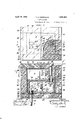
- Fig. I is a plan View of my improved cooler.
- Fig.' II is a longitudinal sectional view of the structure ⁇ taken asindicated by the arrows IIII in Fig. I.
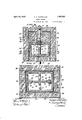
- Fig. III is a cross section taken as indicated by the arrows III-III in Fig ⁇ II;
- Fig. IV is a plan sectional view ofthe cooler in accordance with the arrows IV-IV in Fig. II.
- my 'improved liquid cooler comprises a refrigerating vessel adapted to be trav- 7 ersed by the liquid being cooled, said vessel being in the present instance made to4 closed hollow rectangularV configuration from ceramic or other material having like thermal properties.
- the walls of the refrigerating vesl 10 are quite thick; and said vessel is ⁇ internallyV subdivided by medial longitudinal and transverse bracing partitions 11, ⁇ 12 with apertures 13, 14 through them for coni* tnuous intercommunication between the subdivisions Or cells 15 set apart by said partitioning.
- my improved cooler is intended for connection to the water supply lines in buildings, and to this end I provide pipe nipples 16, 17 which extend into inflow and outflow openings 18, 19 respectively in the bottom and the 'top of the vessel 10 at opposite ends thereof.
- the connec- -60 tionof the pipe nipples, 16, 17 it will be noted,
- the nipple 16 is fitted with a coupling sleeve 26 to enable connection direct to the water supply pipe P; while the nipple 17 has an attached elbow 27 for coupling to a discharge pipe 1P 70 which may lead to a suitable drain faucet, not illustrated.
- a jacket 30 of heavy insulation completely encloses the refrigei'ating vessel 10 except for provision ⁇ of a space 31 to ac- 75 commodate a standardized unit block B of solid carbon dioxide or the like in surface contact with a portion of the vessel top exposed within said space.
- the jacket 30 is constructed to the 80 form of a box from boards of cork or-cork composition which are secured togetherby non-metallic dowels 82 preferably of wood.
- a portion B5 of the top of the jacket 30 is removable and serves as a protective closure lid for the refrigerant space 31, said closure lid being likewise constructed from cork or cork composition to correspond with the rest ofthe jacket 30, and surfaced with cementitious material or sealing composition as shown at 86.
- the'outflow pipe nipple 17 passes through a block 37 of insulation which closes in a portion of the space ma over the top of the vessel 10, and it is sealed in through the cohesive action of the cementitious material or sealing composition 33 on the adjacent side walls and the fixed portion of the jacket top.
- openings 38, 39 of a liberal diameter are provided in the jacket 30, such openings being subsequently packed with a fibrous insulating medium 40 such as compressed vegetable fiber, for example.
- the outflow pipe nipple 17 is amply protected against the effects of the solid carbon dioxide block B and thus safeguarded against freezing.
- the refrigerating influence of the carbon dioxide-block B is moderated, as a consequence of communication by conduction through the thick walls and partitions of the vessel 10, to the extent of precluding freezing of the water with maintenance of the latter at a cool palatable drinking temperature somewhat above the freezing point.
- the flow of the water in the structure is shown by the arrows as being upward through the nipple 16, thence circuitously through the several inter-communicating cells 11 of the refrigerating vessel l0, and out through the nipple 17 and discharge pipe P.
- the efcient seal formed by the cementitious material or sealing composition 38 prevents downward escape of the free-heavier than air-carbon dioxide gas liberated through sublimation of the block B, so that an atmosphere of the cold gas is at all times maintained within the structure around the vessel 10, it being permittedl to escape only by slow seepage upward around the joints between the removable cover lid 35 and the jacket 30.
- a cooler of the character described comprising a closed hollow refrigerating vessel of ceramic material adapted to be traversed by the liquid being cooled, said vessel having capacity to moderate thermic conductivity whereby the liquid is cooled without freezing; and a heavy thermo-insulate acket completely enveloping said vessel except for a space to accommodate a block of solid carbon dioxide in surface contact with an exposed portion of the vessel.
- a liquid cooler comprising -a closed hollow refrigerating vessel of ceramic material adapted for flow therethrough of the liquid being cooled, said vessel having capacity to moderate thermic conductivity whereby the liquid is cooled without freezing, and a heavy thermo-insulate jacket, complet-ely enveloping said vessel with the exception of a space to accommodate a block of solid refrigerant in suface contact with an exposed face of the vesse 3.
- a cooler of the character described comprising a closed hollow refrigerating vessel of ceramic material provided with an inlet and an outlet at opposite ends to predetermine upward horizontal flow therethrough of the liquid being cooled, said vessel having thick walls to moderate thermic conductivity whereby the liquid is cooled without danger of freezing; and a heavy thermo-insulate jacket completely enveloping the refrigerating vessel except for a space to accommodate a block of solid carbon dioxide in surface contact with an exposed upper portion of the vessel.
- a cooler of the character described comprising a closed hollow refrigerating vessel of ceramic material provided with an outlet and an inlet respectively in its top and bottom at opposite ends to predetermine iiow horizontally therethrough of the liquid being cooled, said vessel having thick walls to moderate thermic conductivity whereby the liquid is cooled without danger of freezing; and a heavy thermo-insulate jacket completely enveloping the refrigerating vessel except for a space to accommodate a block of solid carbon dioxide in surface contact with an exposed upper portion of the vessel.
- a cooler of the character described comprising a closed hollow refrigerating vessel of ceramic material formed interiorly with a number of intercommunicating cells adapted forV How therethrough of the liquid being cooled, the walls of said vessel and cells being comparatively thick to moderate thermic conductivity whereby the liquid is cooled without danger of freezing; and a thickwalled thermo-insulate jacket completely enveloping the refrigerating vessel except for a space to accommodate a block of solid carbon dioxide in surface contact with an exposed top portion of the vessel.
- a cooler of the character described comprising a closed hollow refrigerating vessel of ceramicl material adapted for upward flow therethrough of the liquid being cooled, the walls of said vessel and cells being comparatively thick to moderate thermic conductivity whereby the liquid is cooled without danger of freezing; and a heavy thermo-insulate jacket completely enveloping the refrigerat ing vessel except for a space to accommodate a block of solid carbon dioxide in surface contact with an exposed upper portion of the vessel top, said acket being sealed fluid-tight all around and fitted at the top with a removable closure of insulation through which access is had to the space for the refrigerant.
- a cooler ofthe character described comprising a closed hollow refrigerating vessel of ceramic material adapted for flow therethrough of the liquid being cooled, the walls of said vessel and cells being comparatively thick to moderate thermic conductivity whereby the liquid is cooled without danger of freezing; a heavy thermo-insulate acket completely enveloping the refrigerating vessel except for a space to accommodate a block of carbon dioxide in surface contact with the top portion of the vessel; and outflow and inflow piping leading through the insulation of the acket with nipple ends connecting respectively into and sealed liquid-tight to the top and bottom of the refrigerating vessel at opposite ends thereof with predetermination of horizontal upward flow of the liquid through the latter.
- a hollow refrigerating vessel for liquid coolers integrally formed wholly of ceramic material with apertured longitudinal and transverse partitioning dividing its interior into a number of intercommunicatin cells adapted to be traversed successively y the liquid being cooled, the walls of said vessel and cells being comparatively thick to moderate thermic conductivity.
Landscapes
- Engineering & Computer Science (AREA)
- Chemical & Material Sciences (AREA)
- Chemical Kinetics & Catalysis (AREA)
- Combustion & Propulsion (AREA)
- Physics & Mathematics (AREA)
- Mechanical Engineering (AREA)
- Thermal Sciences (AREA)
- General Engineering & Computer Science (AREA)
Description
April 19, 1932. T. s. MERRYLEES 1,854,853
LIQUID COOLER Filed March 29, 1929 2 Sheets-Sheet l IIJEVIIlI/ l WITNESSES J6 IN VEN TOR:
A TTORNEYS.
uw f @M April 19, 1932-' T. s. MERRYLEES 1,854,853
LIQUID COOLER Filed March 29, 1929 2 Sheets-Sheet 2 l l l, oaf/x, WITNE ES 10 i5 INVENTOR.-
451/ i l! I 52 @gw/w l Thomas Werff/lees,
' MW ATTORNEYS.
Patented Apr. 19, 1932 UNITED STATES THOMAS S. MERRYLEES, OFvYEADON, PENNSYLVANIA LIQUID COOLER Appiieation mea March 29,1929. serial No. 350,953.
This invention relates to coolers for refrigerating liquids, and has more particular ref,- erence to coolers intended for refrigeration of drinking water. Vrf The purpose of my invention is to enable cooling of water with the aid of powerful refrigerants like solid carbon dioxide and to attain this end with economic use of the refr-igerant incident to maintenance of the wa- W/ ter at a palatable drinking temperature above the freezing point. These advantages I aim to secure in a ycooler structure which is simple in design and construction, inexpensiveV to manufacture, capable of easy connection to l the Water supply lines of dwellings, oiice buildings, etc., and of aording at all times an adequate supply of cold water under normal conditions of demand upon it.
Still other objects and advantages will appear in the course of the detailed description following of the typicalembodiment of this invention shown in the drawings, whereof Fig. I is a plan View of my improved cooler.
Fig.' II is a longitudinal sectional view of the structure `taken asindicated by the arrows IIII in Fig. I.
Fig. III is a cross section taken as indicated by the arrows III-III in Fig` II; and,
Fig. IV is a plan sectional view ofthe cooler in accordance with the arrows IV-IV in Fig. II.
AFrom these illustrations it will be observed that my 'improved liquid cooler comprises a refrigerating vessel adapted to be trav- 7 ersed by the liquid being cooled, said vessel being in the present instance made to4 closed hollow rectangularV configuration from ceramic or other material having like thermal properties. As shown to the best advantagein Figs. II, III and IV, the walls of the refrigerating vesl 10 are quite thick; and said vessel is` internallyV subdivided by medial longitudinal and transverse bracing partitions 11, `12 with apertures 13, 14 through them for coni* tnuous intercommunication between the subdivisions Or cells 15 set apart by said partitioning. In the form herein illustrated, my improved cooler is intended for connection to the water supply lines in buildings, and to this end I provide pipe nipples 16, 17 which extend into inflow and outflow openings 18, 19 respectively in the bottom and the 'top of the vessel 10 at opposite ends thereof. To secure vthese pipe nipples 16, 17 fluid tight within the openings 18, 19, I employ bushings 2O of .55 rubber or the like which are compressed, 'for radial expansion into'intimate contact with the edges of said openings, between end shoulder flanges 21 on the nipples 16, 17 and nuts 22 in engagement with threads 23. The connec- -60 tionof the pipe nipples, 16, 17 it will be noted,
is made along the lengthwise medial vertical plane of the vessel 10, the longitudinal vpartitioning 11 being out away to provide clearances at these points as shown at 24, 25 .for the 65 purpose. In the present instance, the nipple 16 is fitted with a coupling sleeve 26 to enable connection direct to the water supply pipe P; while the nipple 17 has an attached elbow 27 for coupling to a discharge pipe 1P 70 which may lead to a suitable drain faucet, not illustrated.
As shown, a jacket 30 of heavy insulation completely encloses the refrigei'ating vessel 10 except for provision `of a space 31 to ac- 75 commodate a standardized unit block B of solid carbon dioxide or the like in surface contact with a portion of the vessel top exposed within said space. For convenience in manufacture, the jacket 30 is constructed to the 80 form of a box from boards of cork or-cork composition which are secured togetherby non-metallic dowels 82 preferably of wood. Incident to assembling, the constituent parts of the jacket 30 V.are buttered with a heavy .95 layer 33 of cementitious material having insulating properties or like sealing composition, and secured with the dowel-s 32 while said material or composition is still moist, thereby insuring {luid-tight joints all around. A portion B5 of the top of the jacket 30 is removable and serves as a protective closure lid for the refrigerant space 31, said closure lid being likewise constructed from cork or cork composition to correspond with the rest ofthe jacket 30, and surfaced with cementitious material or sealing composition as shown at 86. Within the jacket 30, the'outflow pipe nipple 17 passes through a block 37 of insulation which closes in a portion of the space ma over the top of the vessel 10, and it is sealed in through the cohesive action of the cementitious material or sealing composition 33 on the adjacent side walls and the fixed portion of the jacket top. To facilitate connection of the pipe nipples 16, 17 during assembling of the structure, openings 38, 39 of a liberal diameter are provided in the jacket 30, such openings being subsequently packed with a fibrous insulating medium 40 such as compressed vegetable fiber, for example. ByV
virtue of embedment in insulatory material 87, 40 as described, the outflow pipe nipple 17 is amply protected against the effects of the solid carbon dioxide block B and thus safeguarded against freezing.
In the operation of the cooler, the refrigerating influence of the carbon dioxide-block B is moderated, as a consequence of communication by conduction through the thick walls and partitions of the vessel 10, to the extent of precluding freezing of the water with maintenance of the latter at a cool palatable drinking temperature somewhat above the freezing point. The flow of the water in the structure is shown by the arrows as being upward through the nipple 16, thence circuitously through the several inter-communicating cells 11 of the refrigerating vessel l0, and out through the nipple 17 and discharge pipe P. The efcient seal formed by the cementitious material or sealing composition 38 prevents downward escape of the free-heavier than air-carbon dioxide gas liberated through sublimation of the block B, so that an atmosphere of the cold gas is at all times maintained within the structure around the vessel 10, it being permittedl to escape only by slow seepage upward around the joints between the removable cover lid 35 and the jacket 30.
Having thus described my invention, I claim:
1. A cooler of the character described comprising a closed hollow refrigerating vessel of ceramic material adapted to be traversed by the liquid being cooled, said vessel having capacity to moderate thermic conductivity whereby the liquid is cooled without freezing; and a heavy thermo-insulate acket completely enveloping said vessel except for a space to accommodate a block of solid carbon dioxide in surface contact with an exposed portion of the vessel.
2. A liquid cooler comprising -a closed hollow refrigerating vessel of ceramic material adapted for flow therethrough of the liquid being cooled, said vessel having capacity to moderate thermic conductivity whereby the liquid is cooled without freezing, and a heavy thermo-insulate jacket, complet-ely enveloping said vessel with the exception of a space to accommodate a block of solid refrigerant in suface contact with an exposed face of the vesse 3. A cooler of the character described comprising a closed hollow refrigerating vessel of ceramic material provided with an inlet and an outlet at opposite ends to predetermine upward horizontal flow therethrough of the liquid being cooled, said vessel having thick walls to moderate thermic conductivity whereby the liquid is cooled without danger of freezing; and a heavy thermo-insulate jacket completely enveloping the refrigerating vessel except for a space to accommodate a block of solid carbon dioxide in surface contact with an exposed upper portion of the vessel.
4. A cooler of the character described comprising a closed hollow refrigerating vessel of ceramic material provided with an outlet and an inlet respectively in its top and bottom at opposite ends to predetermine iiow horizontally therethrough of the liquid being cooled, said vessel having thick walls to moderate thermic conductivity whereby the liquid is cooled without danger of freezing; and a heavy thermo-insulate jacket completely enveloping the refrigerating vessel except for a space to accommodate a block of solid carbon dioxide in surface contact with an exposed upper portion of the vessel.
5. A cooler of the character described comprising a closed hollow refrigerating vessel of ceramic material formed interiorly with a number of intercommunicating cells adapted forV How therethrough of the liquid being cooled, the walls of said vessel and cells being comparatively thick to moderate thermic conductivity whereby the liquid is cooled without danger of freezing; and a thickwalled thermo-insulate jacket completely enveloping the refrigerating vessel except for a space to accommodate a block of solid carbon dioxide in surface contact with an exposed top portion of the vessel.
6. A cooler of the character described comprising a closed hollow refrigerating vessel of ceramicl material adapted for upward flow therethrough of the liquid being cooled, the walls of said vessel and cells being comparatively thick to moderate thermic conductivity whereby the liquid is cooled without danger of freezing; and a heavy thermo-insulate jacket completely enveloping the refrigerat ing vessel except for a space to accommodate a block of solid carbon dioxide in surface contact with an exposed upper portion of the vessel top, said acket being sealed fluid-tight all around and fitted at the top with a removable closure of insulation through which access is had to the space for the refrigerant.
7. A cooler ofthe character described comprising a closed hollow refrigerating vessel of ceramic material adapted for flow therethrough of the liquid being cooled, the walls of said vessel and cells being comparatively thick to moderate thermic conductivity whereby the liquid is cooled without danger of freezing; a heavy thermo-insulate acket completely enveloping the refrigerating vessel except for a space to accommodate a block of carbon dioxide in surface contact with the top portion of the vessel; and outflow and inflow piping leading through the insulation of the acket with nipple ends connecting respectively into and sealed liquid-tight to the top and bottom of the refrigerating vessel at opposite ends thereof with predetermination of horizontal upward flow of the liquid through the latter.
8. A hollow refrigerating vessel for liquid coolers integrally formed wholly of ceramic material with apertured longitudinal and transverse partitioning dividing its interior into a number of intercommunicatin cells adapted to be traversed successively y the liquid being cooled, the walls of said vessel and cells being comparatively thick to moderate thermic conductivity.
In testimony whereof, I have hereunto signed my name at Philadelphia, Pennsylvania, this 27th day of March, 1929.
THOMAS S. MERRYLEES.
Priority Applications (1)
| Application Number | Priority Date | Filing Date | Title |
|---|---|---|---|
| US350953A US1854853A (en) | 1929-03-29 | 1929-03-29 | Liquid cooler |
Applications Claiming Priority (1)
| Application Number | Priority Date | Filing Date | Title |
|---|---|---|---|
| US350953A US1854853A (en) | 1929-03-29 | 1929-03-29 | Liquid cooler |
Publications (1)
| Publication Number | Publication Date |
|---|---|
| US1854853A true US1854853A (en) | 1932-04-19 |
Family
ID=23378916
Family Applications (1)
| Application Number | Title | Priority Date | Filing Date |
|---|---|---|---|
| US350953A Expired - Lifetime US1854853A (en) | 1929-03-29 | 1929-03-29 | Liquid cooler |
Country Status (1)
| Country | Link |
|---|---|
| US (1) | US1854853A (en) |
Cited By (2)
| Publication number | Priority date | Publication date | Assignee | Title |
|---|---|---|---|---|
| US9527652B2 (en) | 2014-07-28 | 2016-12-27 | Sovaro Coolers, LLC | Transportable transparent cork-insulated cooler |
| US10322867B2 (en) | 2014-07-28 | 2019-06-18 | Sovaro Coolers, LLC | Transportable transparent cork-insulated cooler |
-
1929
- 1929-03-29 US US350953A patent/US1854853A/en not_active Expired - Lifetime
Cited By (2)
| Publication number | Priority date | Publication date | Assignee | Title |
|---|---|---|---|---|
| US9527652B2 (en) | 2014-07-28 | 2016-12-27 | Sovaro Coolers, LLC | Transportable transparent cork-insulated cooler |
| US10322867B2 (en) | 2014-07-28 | 2019-06-18 | Sovaro Coolers, LLC | Transportable transparent cork-insulated cooler |
Similar Documents
| Publication | Publication Date | Title |
|---|---|---|
| US4131158A (en) | Storage arrangement for thermal energy | |
| US1854853A (en) | Liquid cooler | |
| CN107631655A (en) | A kind of mine wellhead anti-freezing heater | |
| CN207796542U (en) | A kind of steam energy storage device | |
| CN104990438B (en) | A kind of phase-change type heat-storing device with inner water-tank | |
| CN108332591A (en) | A kind of cold-storage and thermal storage integrated apparatus | |
| CN203674957U (en) | Water tank with inclined temperature layer and for direct current power transmission converter valve | |
| CN204987991U (en) | Take built -in water tank's looks variant heat -retaining device | |
| CN208635402U (en) | A multi-channel gravity heat pipe to enhance heat transfer and rapid charging and cooling system | |
| JPS5952152A (en) | Heat exchanger | |
| JPS6355611B2 (en) | ||
| US1944894A (en) | Water heater | |
| US2078129A (en) | Refrigerating apparatus | |
| US1859229A (en) | Liquid cooling apparatus | |
| US1958403A (en) | Heat transfer structure | |
| US1887693A (en) | Refrigerating apparatus and method | |
| CN208205852U (en) | A kind of laboratory hot oil quickly cooling device | |
| CN222298561U (en) | Heat exchange structure for hot box assembly | |
| RU2015481C1 (en) | Water cooling device | |
| JPS593265Y2 (en) | Heat exchanger | |
| CN216694167U (en) | Reation kettle frozen water circulation cooling system | |
| CN219300240U (en) | Antifreezing heat insulation sleeve | |
| CN115979038B (en) | A deep-sea phase-change heat and cold storage device and its operation method | |
| CN114508626B (en) | Thermal insulation valve rod and use method thereof | |
| US1752277A (en) | Refrigerative heat-insulating apparatus and method |