US1854851A - Article positioning device for sewing machines - Google Patents
Article positioning device for sewing machines Download PDFInfo
- Publication number
- US1854851A US1854851A US374980A US37498029A US1854851A US 1854851 A US1854851 A US 1854851A US 374980 A US374980 A US 374980A US 37498029 A US37498029 A US 37498029A US 1854851 A US1854851 A US 1854851A
- Authority
- US
- United States
- Prior art keywords
- article
- arm
- positioning
- positioning device
- recess
- Prior art date
- Legal status (The legal status is an assumption and is not a legal conclusion. Google has not performed a legal analysis and makes no representation as to the accuracy of the status listed.)
- Expired - Lifetime
Links
- 238000009958 sewing Methods 0.000 title description 4
- 230000002093 peripheral effect Effects 0.000 description 2
- 238000010276 construction Methods 0.000 description 1
- 239000004744 fabric Substances 0.000 description 1
- 238000007493 shaping process Methods 0.000 description 1
Images
Classifications
-
- D—TEXTILES; PAPER
- D05—SEWING; EMBROIDERING; TUFTING
- D05B—SEWING
- D05B21/00—Sewing machines with devices for automatically controlling movement of work-carrier relative to stitch-forming mechanism in order to obtain particular configuration of seam, e.g. programme-controlled for sewing collars, for attaching pockets
- D05B21/007—Sewing machines with devices for automatically controlling movement of work-carrier relative to stitch-forming mechanism in order to obtain particular configuration of seam, e.g. programme-controlled for sewing collars, for attaching pockets to obtain circular or elliptical seams
Definitions
- the invention relates to new and useful improvements in an article positioning device for sewing machines, and more particularly to a device for positioning an article which is circular or arcuate in configuration.
- An object of the invention is to provide an article positioning device of the above character for centering a circular article relative to a feeding and directing means so that the peripheral edge of the article may be properly presented step by step to the stitching point for the covering of the edge portion thereof with stitches.
- a further object of the invention is to provide a positioning device of theabove character with an ad ustable stop for limiting its movement toward the stitching point so that articles of different sizes maybe -properly centered relative to the feeding and directing means therefor.
- a still further object of the invention is to provide a positioning device of the above character which is automatically held retracted away from the article while it is being stitched.
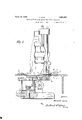
- Fig. l is a view partly in section and partly in end elevation showing a feeding and directing mechanism for feeding and directs ing a circular article while it is being stitched with the improved article positioning means applied thereto.
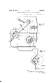
- Fig. 2 is a plan view of a portion of the i work support showing the clamping plates a portion of the article is covered with stitches.
- This feeding mechanism includes cooperating clamping platesrotating about a vertical axis at one side of the stitching point.
- the lower clamping plate is carried by a a sleeve provided with a gear and the sleeve is mounted in a bracket.
- a clutch which is intermittently rotated by suitable devices operated by the shaft beneath the work support.
- a gear Associated with the clutch is a gear and this gear through an intermediate gear rotates the gear formed as a part of the sleeve which supports the lower clamping member.
- the present invention has to do particularly with a device for positioning the article to be stitched so'that it will be properly centered between these clamping plates so that when the article is turned by the clamping plates the stitches will be passed through the edge of the article at a uniform distance back from the periphery thereof.
- This positioning device includes an arm which is pivoted to the work support. The arm is moved by a spring away from the stitching point into contact with a stop. The arm is provided with a face which is shaped so as to place the article with the center thereof in a predetermined position on the arm relative to its pivotal support.
- the arm is swung manually to position the article between the clamping plates and this predetermined positioning of the article on the arm insures that the center of the article will be properly positioned between the clamping plates.
- An adjustable stop is provided for limiting the movement of the arm so as to center the article in the axis of rotation of the clamping plates.
- the article to be stitched is indicated at a and the center of the article at 70.
- This article is clamped between the feed plates 0 and b.
- the upper feed plate a is mounted on a bracket arm (Z for free rotation and this bracket arm is carried by the presser bar so that the upper clamping plate 0 is yieldingly pressed toward the lower clamping plate and will clamp the article between said plates.
- the lower clamping plate I is carried by a sleeve mounted in a bracket and this sleeve is positively rotated by a train of gears and a clutch, all of which is fully shown, described and claimed in my co-pending application.
- the arm 6 is formed with an offset 10 portion, the inner face of' which, as shown in Fig. 2, is curved atf. Along this curved edge is a raised flange f.
- the curvature of the plate is substantially the same as the curvature of the article to be stitched so that the article a may be placed in this positioning recess in the arm 6.
- the curved recess extends through an arc of approximately 180 degrees, and thus it is that the disc when positioned in the recess will be set at a fixed distance from the center of the pivot stud g.
- the work support is provided with an extension 7" and this arm 6 moves close to the upper face of the work support, as clearly shown in Fig. 1.
- the article is really supported on the work support and the arm is merely for the purpose of positioning the article along the work support between the feed plates 0 and b.
- the lower feed plate I has its upper face substantially on a level with the upper face of the cloth plate 7t. hen an article is to be positioned it is placed in the locating recess ofthe arm 6.
- the upper clamping plate is raised by lifting the presser foot and thenthe arm 6 is swung until it is 3% brought into engagement with the adjustable stop a which is attached to the work supporth'and held in adjusted positions thereon by screws 12 passing through a slot 0 in this adjustable stop.
- This adjustable stop is my placed so that when the arm 6 makes contact therewith the center 70 of the disc will be in alignment with the axis of rotation of the plates 0 and b.
- the positioning recess in the arm 6 is so formed and shaped that the center 4 3 k of the article when in engagement with the recess will'be the same distance from the axis of the pivot stud g as the rotating axis of the plates 0 and b from said axis of the pivot stud.
- the article will be 59; placed between the clamping plates so that the center of thearticle will be in the axis of rotation of the plates, and when the plates clamp the article and feed and direct the same to the stitching mechanism the needle will always enter .the article auniform distance from the peripheral edge thereof.
- a sewing machine including in combinat tion a work support, clamping plates for feeding and directing a circular article to the stitching mechanism, said clamping plates being mounted so as to rotate about a set axis at one side of the stitching point, a'positioning arm, means for pivoting said arm to the work 1 support, an adjustable stopfor limiting the movement of said arm in a direction toward the stitching point, said arm having a positioning recess formed therein for receiving the article to be stitched, said recess being so shaped as to place a circular article in a predetermined position relative to the arm, said positioning recess being so located relative to the pivotal support for said arm that when said arm is movedinto engagement with the stop the center of the article to be stitched will be positioned at the axis of rotation of the clamping plates, said arm being disposed adjacent the upper face of the work support whereby the article may be positioned on the work support and moved along the same by said arm, said lower clamping plate having its upper face substantially flush with the upper face of the work
Landscapes
- Engineering & Computer Science (AREA)
- Textile Engineering (AREA)
- Sewing Machines And Sewing (AREA)
Description
F. LUTZ ARTICLE POSITIONING DEVICE FOR SEWING MACHINES April 19, 1932.
Filed July 1, 1929 2 Sheets-Sheet l i /I'll"? II H gwomtoc [F Q/502x06 Lurz.
" WWW Chicane/g5 April 19, 1932. F. .LUTZ 1,854,851
ARTICLE POSITIONING DEVICE FOR SEWING MACHINES Filed July 1, 1929 2 Sheets-Sheet 2 Patented Apr. 19, 1932 UNITED STATES PATENT QFFI'CE rmnnmcn LUTZ, or srtrrreanr, GnnMANY, assrenor. ro UNION srncran Masonr- NENFABRIK, G. M. B. H., orsrnrreanr, GERMANY ARTICLE POSITIONING DEVICE FOR SEWING MACHINES Application filed July 1, 1929, Serial N0. 374,980, and. in Germany January 12, 1929.
v The invention relates to new and useful improvements in an article positioning device for sewing machines, and more particularly to a device for positioning an article which is circular or arcuate in configuration.
An object of the invention is to provide an article positioning device of the above character for centering a circular article relative to a feeding and directing means so that the peripheral edge of the article may be properly presented step by step to the stitching point for the covering of the edge portion thereof with stitches.
A further object of the invention is to provide a positioning device of theabove character with an ad ustable stop for limiting its movement toward the stitching point so that articles of different sizes maybe -properly centered relative to the feeding and directing means therefor.
A still further object of the invention is to provide a positioning device of the above character which is automatically held retracted away from the article while it is being stitched.
In the drawings Fig. l is a view partly in section and partly in end elevation showing a feeding and directing mechanism for feeding and directs ing a circular article while it is being stitched with the improved article positioning means applied thereto.
Fig. 2 is a plan view of a portion of the i work support showing the clamping plates a portion of the article is covered with stitches.
This feeding mechanism includes cooperating clamping platesrotating about a vertical axis at one side of the stitching point. The lower clamping plate is carried by a a sleeve provided with a gear and the sleeve is mounted in a bracket. Also mounted on the bracket is a clutch which is intermittently rotated by suitable devices operated by the shaft beneath the work support. Associated with the clutch is a gear and this gear through an intermediate gear rotates the gear formed as a part of the sleeve which supports the lower clamping member. Thus it is that the article to be stitched is positively rotated about a center at one side of the stitching point.
The present invention has to do particularly with a device for positioning the article to be stitched so'that it will be properly centered between these clamping plates so that when the article is turned by the clamping plates the stitches will be passed through the edge of the article at a uniform distance back from the periphery thereof. This positioning device includes an arm which is pivoted to the work support. The arm is moved by a spring away from the stitching point into contact with a stop. The arm is provided with a face which is shaped so as to place the article with the center thereof in a predetermined position on the arm relative to its pivotal support. The arm is swung manually to position the article between the clamping plates and this predetermined positioning of the article on the arm insures that the center of the article will be properly positioned between the clamping plates. An adjustable stop is provided for limiting the movement of the arm so as to center the article in the axis of rotation of the clamping plates.
Referring more in detail to the drawings, the article to be stitched is indicated at a and the center of the article at 70. This article is clamped between the feed plates 0 and b. The upper feed plate a is mounted on a bracket arm (Z for free rotation and this bracket arm is carried by the presser bar so that the upper clamping plate 0 is yieldingly pressed toward the lower clamping plate and will clamp the article between said plates. The lower clamping plate I) is carried by a sleeve mounted in a bracket and this sleeve is positively rotated by a train of gears and a clutch, all of which is fully shown, described and claimed in my co-pending application.
stud g. The arm 6 is formed with an offset 10 portion, the inner face of' which, as shown in Fig. 2, is curved atf. Along this curved edge is a raised flange f. The curvature of the plate is substantially the same as the curvature of the article to be stitched so that the article a may be placed in this positioning recess in the arm 6. The curved recess extends through an arc of approximately 180 degrees, and thus it is that the disc when positioned in the recess will be set at a fixed distance from the center of the pivot stud g.
The work support is provided with an extension 7" and this arm 6 moves close to the upper face of the work support, as clearly shown in Fig. 1. The article is really supported on the work support and the arm is merely for the purpose of positioning the article along the work support between the feed plates 0 and b. The lower feed plate I; has its upper face substantially on a level with the upper face of the cloth plate 7t. hen an article is to be positioned it is placed in the locating recess ofthe arm 6. The upper clamping plate is raised by lifting the presser foot and thenthe arm 6 is swung until it is 3% brought into engagement with the adjustable stop a which is attached to the work supporth'and held in adjusted positions thereon by screws 12 passing through a slot 0 in this adjustable stop. This adjustable stop is my placed so that when the arm 6 makes contact therewith the center 70 of the disc will be in alignment with the axis of rotation of the plates 0 and b. The positioning recess in the arm 6 is so formed and shaped that the center 4 3 k of the article when in engagement with the recess will'be the same distance from the axis of the pivot stud g as the rotating axis of the plates 0 and b from said axis of the pivot stud. Thus it is that the article will be 59; placed between the clamping plates so that the center of thearticle will be in the axis of rotation of the plates, and when the plates clamp the article and feed and direct the same to the stitching mechanism the needle will always enter .the article auniform distance from the peripheral edge thereof.
InFigB of the drawings the arm 6 is shown asformed witha positioning recess wherein the sides of the recess are substantial- 9; 1y at right angles to each other as-indicated at q in the drawings. It will readily be-seen by the diagrammatic illustration in this figu-re thatarticles. of different diameters may be. gauged by these facesso that the center of 5 the articlewill-always be substantially or feeding anddirecting a circular article to the approximately a fixed distance from the axis of the pivot stud g and thus it is that articles of different diameters may be positioned by the same shaping of the recess in the positioning arm.
It is obvious that minor changes in the details of construction may be made without departing from the spirit of the invention as set forth in the appended claims.
Having fully= described myrinventionswhat I claim as new: and desire to secure by Letters Patent, is
1. A sewing-machine-including in combination a work support, clamping plates for so stitching mechanism, said clamping plates being mounted so as to rotate about a set axis at one side of the stitchingpoint, a positioning arm, means for pivoting said armto the work support, an adjustable stop for limiting the movement of said arm in a direction'toward the stitching point, said arm having a positioning recess formed therein for receiving the article to be stitched, said-recess being so shaped-as to place a circular article in a predetermined position relative to the arm, said positioning recess being so located'relative to the pivotal support for said arm that when said arm is moved into engagement with the stop the center of the article to be stitched will be positioned at the axis of rotation of the clamping plates, a spring for moving said arm away from the stitching point, and a stop for limiting the movement of said arm.
2. A sewing machine including in combinat tion a work support, clamping plates for feeding and directing a circular article to the stitching mechanism, said clamping plates being mounted so as to rotate about a set axis at one side of the stitching point, a'positioning arm, means for pivoting said arm to the work 1 support, an adjustable stopfor limiting the movement of said arm in a direction toward the stitching point, said arm having a positioning recess formed therein for receiving the article to be stitched, said recess being so shaped as to place a circular article in a predetermined position relative to the arm, said positioning recess being so located relative to the pivotal support for said arm that when said arm is movedinto engagement with the stop the center of the article to be stitched will be positioned at the axis of rotation of the clamping plates, said arm being disposed adjacent the upper face of the work support whereby the article may be positioned on the work support and moved along the same by said arm, said lower clamping plate having its upper face substantially flush with the upper face of the work support.
. In testimony whereof, I affix my signature.
FRIEDRICH LUTZ.
Applications Claiming Priority (1)
| Application Number | Priority Date | Filing Date | Title |
|---|---|---|---|
| DE1854851X | 1929-01-12 |
Publications (1)
| Publication Number | Publication Date |
|---|---|
| US1854851A true US1854851A (en) | 1932-04-19 |
Family
ID=7746163
Family Applications (1)
| Application Number | Title | Priority Date | Filing Date |
|---|---|---|---|
| US374980A Expired - Lifetime US1854851A (en) | 1929-01-12 | 1929-07-01 | Article positioning device for sewing machines |
Country Status (1)
| Country | Link |
|---|---|
| US (1) | US1854851A (en) |
-
1929
- 1929-07-01 US US374980A patent/US1854851A/en not_active Expired - Lifetime
Similar Documents
| Publication | Publication Date | Title |
|---|---|---|
| US1854851A (en) | Article positioning device for sewing machines | |
| CN108823822B (en) | Three-dimensional rotary feeding sewing machine | |
| US2674963A (en) | Spiral seam producing mechanism for sewing machines | |
| US3276405A (en) | Sewing device with guided control of the sewing cycle | |
| US2107578A (en) | Automatic shaping machine | |
| CN107938179A (en) | A kind of label for clothing sewing device | |
| US1864452A (en) | Feeding mechanism for sewing machines | |
| US1509148A (en) | Machine for forming and stitching tapered collarets | |
| US1884026A (en) | Feeding mechanism for sewing machines | |
| US3439637A (en) | Apparatus to feed superposed webs for seaming | |
| US2610596A (en) | Apparatus for attaching elastic bands to garments | |
| US2249423A (en) | Double head hemming machine | |
| US2187748A (en) | Glass beveling machine | |
| US886568A (en) | Angle-sewing attachment for sewing-machines. | |
| US810297A (en) | Buttonhole-sewing machine. | |
| US1267566A (en) | Sewing-machine. | |
| US647413A (en) | Machine for sharpening twist-drills. | |
| US2207141A (en) | Zigzag machine with two needles and two hooks | |
| US2317698A (en) | Sewing machine mechanism | |
| US1976285A (en) | Wire stitching machine for stitching corrugated cardboard cartons or the like | |
| US2055998A (en) | Can seaming machine | |
| US1570373A (en) | Soft-hat-rounding machine | |
| US1879134A (en) | Cylindrical grinding attachment for surface grinders | |
| US1610232A (en) | Lapping machine | |
| US709311A (en) | Feeding mechanism for sewing-machines. |