US1854827A - Garment or ironing press - Google Patents
Garment or ironing press Download PDFInfo
- Publication number
- US1854827A US1854827A US121306A US12130626A US1854827A US 1854827 A US1854827 A US 1854827A US 121306 A US121306 A US 121306A US 12130626 A US12130626 A US 12130626A US 1854827 A US1854827 A US 1854827A
- Authority
- US
- United States
- Prior art keywords
- movable
- lever
- valve
- cylinder
- press
- Prior art date
- Legal status (The legal status is an assumption and is not a legal conclusion. Google has not performed a legal analysis and makes no representation as to the accuracy of the status listed.)
- Expired - Lifetime
Links
Images
Classifications
-
- D—TEXTILES; PAPER
- D06—TREATMENT OF TEXTILES OR THE LIKE; LAUNDERING; FLEXIBLE MATERIALS NOT OTHERWISE PROVIDED FOR
- D06F—LAUNDERING, DRYING, IRONING, PRESSING OR FOLDING TEXTILE ARTICLES
- D06F71/00—Apparatus for hot-pressing clothes, linen or other textile articles, i.e. wherein there is substantially no relative movement between pressing element and article while pressure is being applied to the article; Similar machines for cold-pressing clothes, linen or other textile articles
- D06F71/04—Apparatus for hot-pressing clothes, linen or other textile articles, i.e. wherein there is substantially no relative movement between pressing element and article while pressure is being applied to the article; Similar machines for cold-pressing clothes, linen or other textile articles power-actuated
- D06F71/06—Apparatus for hot-pressing clothes, linen or other textile articles, i.e. wherein there is substantially no relative movement between pressing element and article while pressure is being applied to the article; Similar machines for cold-pressing clothes, linen or other textile articles power-actuated fluid-actuated
- D06F71/062—Apparatus for hot-pressing clothes, linen or other textile articles, i.e. wherein there is substantially no relative movement between pressing element and article while pressure is being applied to the article; Similar machines for cold-pressing clothes, linen or other textile articles power-actuated fluid-actuated with an upper movable pressing member and a lower fixed pressing member
- D06F71/065—Apparatus for hot-pressing clothes, linen or other textile articles, i.e. wherein there is substantially no relative movement between pressing element and article while pressure is being applied to the article; Similar machines for cold-pressing clothes, linen or other textile articles power-actuated fluid-actuated with an upper movable pressing member and a lower fixed pressing member the upper movable member rotating about a fixed axis
- D06F71/067—Fluid-control mechanisms for controlling the ironing pressure or the movement of the pressure member
Definitions
- This invention relates to pressing machines, such as garment and laundrypresslng or ironing'machines and has for its object a particularly simple and efficient power actuating mechanism to actuate one of the press jaws, and more particularly a power mechanism embodying a reciprocating actuator, as the piston rod of a piston movable in'a cylinder: it further has for its object a particularly simple and efficient means for controlling the flow of motive fluid to the cylinder in such a way that the movable pressing element or head must be preliminarily closed by hand before the motive fluid can be admitted to the cylinder, and the preliminary closing movement of the head is independent of the actuator, and does not move the actuator so that the full power stroke of the piston is utilized in applying pressure.
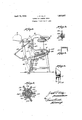
- Figure 1 is a side elevation of a machine embodying my invention.
- Figure 2 is a detail sectional view of the manual control valve shown in open-press position.
- Figure 3 is a detail sectional view of the cut off valve automatically operated by a movable part of the machine.
- Figure 4 is a detail fragmentary view of the cylinder'and piston movable therein.
- Figure 5 is a sectional view of the press frame on line 55, Figure 1, parts being omitted.
- I have here illustrated my invention as embodied in a conventional type of garment and laundry pressing machine comprising press jaws such as a buck 1 and a head 2 movable toward and from the buck, the buck being carried by a goose neck 3, which in turn is mounted on a frame 4.
- the head 2 is carried by a yoke or lever 5 pivoted at 6 be tween its ends to a standard 7 rising from the frame, and said lever carries the head 2 at itsfront end, and is connected at its rear to open-the crating movement.
- a suitable handle 8 is mounte on'the front of the yoke by means of which the head 2 is preliminarily closed by hand, a counter weight 9 tending press being mounted on the rear end thereof.
- the cylinder 10 is the cylinder and 11 the piston movable in the cylinder and having a rod 12, the piston and its rod constituting a reciprocating actuator.
- the cylinder is mounted in the rear leg 13 of the machine of which the standard 7 is an upward extension and is pivoted at 12a therein so as to have an op-
- the rear leg is in the form of a channel. It' will be understood that the frame has but a single rear leg centrally located.
- the motion transmitting mechanism be-
- the actuator or rollers 14 at its ends includes a part with which the actuator or rollers 14 at its ends has sliding connection, this part being a lever 15 pivoted between its ends at 16 to the frame, and having one arm pivoted at 17 to the lower end of a link 18, the upper end of which is pivoted at 19 to the yoke lever, the other arm of the lever 15 coacting with the rollers 14 which rollers slide or move lengthwise of the lever from its axis toward the outer end of the lever during the power stroke.
- Each of the rollers 14 is guided in its movement by a cam slot 20 formed in the tively to the slot, so that a long movement of the piston is transferred'into a short movement of the lever 15, and finally as the roller approaches the end of the arm 15, it takes an abrupt rearward movement to apply the final pressure due to a rearward deflection 22 at the lower end of the slot 20.
- the head Owing to the sliding connection between the reciprocating actuator or piston rod 12 and the part or lever 15, the head can be preliminarily closed without requiring any movement of the actuator 12 so that the full throw of the actuator 12 is utilized in applying the final heavy pressure, and the long throw of the actuator is converted into power or a short movement of the lever 15 due to the movement of the actuator 12 or its follower l4 lengthwise of the lever.
- Motive fluid as steam or air is supplied to the cylinder from a suitable source of supply through a ipe 23 and is controlled in its flow to and rom the cylinder 10 by a valve 24 having a. manually operated handle 25.
- the piston here shown is double acting and in operation the motive fluid enters the pipe 23 and past an automatic safety means comprising a cut out valve 26 to be presently described, then through a pipe 27 to'the intake port 28 in the valve casing of a valve 24:, thence through the passage 29 of the core or movable member 30 of said .valve, through port 31 and a pipe 32 to the upper end of the cylinder so that the piston is depressed to the full end of its throw.
- the fluid exhausts from the lower end of the cylinder through pipe 33, port 34 of the exhaust valve 21, valve passage 35 of the valve 30 and out through the exhaust port 36.
- valve member 30 is moved by the handle 25 into the position shown in Figure 2 so that the air enters the bottom of the cylinder through pipe 37 port 38, passage 35, out through port 34, and at the same time the air exhausts from the top of the cylinder through the pipe 32, port 31, valve passage 29 and exhaust passage 38.
- the safety valve means 26 shown in Figure 3 is a one way valve normally in closed position when the press is open, and arranged so that its passage is brought into alignment with the pipes 23 and 27 only after the head 2 has been preliminarily closed so that ordinarily the motive fluid from feed pipe 23 cannot be led into the cylinder unless the head has been preliminarily closed.
- the valve 26 is a rotary valve, the rotatable part of which has a rock arm 40 thereon which is connected by a link 41 to the rear arm of yoke lever 5; thus power can be ,applied to the head only after it has been brought down to preliminary closed position by hand.
- the head can be opened at any time by operating the control valve handle 25 so as to permit the air to exhaust from the upper end of the cylinder, and enter the lower end through the pipe 37.
- the press head is opened as the piston moves upwardly in the cylinder by the counterweight 9 and countersprings.
- This machine is particularly advantageous in that it provides a way by which in a machine operated by a cylinder the head must be preliminarily closed by hand, and another Also the full stroke of the piston is utilized to apply pressure and no part of the stroke utilized to preliminarily close the ,press.
- a safety valve means 26 functions to render the control handle 25 ineffective until after the press head has reached safe position on the buck.
- the valve 26 may be a one-way valve means, as shown in the illustrated example of the invention, and thru which a flow of air takes place toward the frontof the press to the valve and handle means 24-25. to render the latter effective to produce heavy pressure between the jaws 1 and 2 only. after the press has closed.
- the one-way safetyvalve means 26 may be operatively connected with the press lever 5 and automatically opened thereby after the head reaches the buck.
- the press head 2 is capable of being closed or moved toward the buck without in any way being under the driving force of the heavy pressure cylinder 10.
- the one-way safety'valve means 26 cuts out the power cylinder 10 until it is safe to admit air pressure to the motor means 10. What I claim is .1.
- cooperating pressing elements one of which is movable toward and from the other, the movable element having a handle associated therewith by which it is preliminarily closable toward the other, means for applying pressure to the movable element after it has been preliminarily closed com rising a cylinder, a piston movable in the cyli parts movable with the movableelement dur ing its preliminary closing movement independently of the piston, and means for controlling the flow of motive fluid to and from the cylinder including a conduit having a normally closed valve therein, and connections between said valve and the movable element whereby the preliminary closing movement of the movable element opens the valve.
- cooperating pressing elements one of which is movable toward and from the other, the movable element having a handle by means of which it is moved preliminarily toward closed position
- means for actuating the movable element including a cylinder, a piston having a piston rod movable in the cylinder, motion transmitting means between the piston rod and the movable element, a manually operated valve arranged to control the flow of motive fluid to and from the cylinder, a second nor-- nder, motion transmitting ment of the movable element by said handle, and connections between the second valve and the movable element whereby the preliminary closing movement of the movable element by the handle opens saidfvalve and the opening of said movable element closes said valve.
- the movable eleto the movable element to be operable into open position by the movable element during the movement thereof by the handle and into closed position byv the opening movement of the movable element.
- means for ap plying pressure to the movable element after it has been preliminarily closed comprising a cylinder, a piston having a piston rod movable in the cylinder and having a cam follower, motion transmitting. means between the piston rod andthe movable element ineluding a part with. which the piston rod has a sliding engagement and .a cam engaging the follower of the piston rod for guiding the rod during its movement.
- means for applying pressure to the, movable element after it has been preliminarily closed comprising a cylinder, a piston having a piston rod movable in the cylinder and having a cam follower,
- motion transmitting means between the piston rod and the movable element including a lever, the piston rod having a follower mov able lengthwise of the lever, and a stationary cam engaging the follower of the piston rod for guiding it during its movement.
- a pressing machine cooperating pressing elements, one of which is movable toward and from the other, the movable element having a handle associated therewith by which it is preliminarily movable toward closed position, a yoke lever supporting the movable element, a link pivoted to the yoke lever, a motion transmitting lever pivoted between its ends and one arm thereof being pivoted to the link, and a reciprocating actuator coacting with the other arm of the lever and having a sliding connection therewith.
- a pressing machine cooperating pressing elements, one of which is movable toward and from the other, the movable element having a handle associated therewith by which it is preliminarily movable toward closed position, a yoke lever, a supporting frame supporting the movable element, a-link pivoted to the yoke lever, a motion transmitting lever pivoted between its ends and one arm thereof being pivoted tothe link, and a reciprocating actuator coacting with the other arm of the lever and having sliding connection therewith, the frame being formed with a cam slot, and the actuator having a follower movable along the slot.
- means for applying pressure to the movable element after it has been preliminarily closed comprising a cylinder, a double acting piston movable in the cylinder and motion transmitting parts between the piston rod and the movable element, pipes for conducting a motive fluid to and from opposite ends of the cylinder, a manually operable valve for controlling flow of motive fluid through said pipes and a normally closed the end of the cylinder into which the motive fluid enters to apply pressure to the movable velement, and connections between said out out toward closed position
- means for applying pressure to the movable element after it has een prehminarily closed comprising a cylcut out valve in the intake pipeleading to a inder, a piston movable in the cylinder and having a piston rod, motion transmitting means between the piston rod and the mov able element including
- cooperating pressing elements one of which is movable toward and from the other, operator-operated means for preliminarily closing the movable element, means for applying pressure to the movable element after it has been preliminarily closed comprising a fluid operated motor, a feed line for the motive fluid, a normally closed valve, a manually operable valve in series in the feed line, and means operated by the preliminary closing movement" of the movable element to open the normally closed valve.
- a pressing machine comprising a frame, cooperating pressing elements, one of which is movable toward and from the other, actuating means for the movable element comprising a reciprocating actuator having a follower, a motiontransmitting lever between the actuator and the movable element along which lever the follower moves, and a stationary cam for guiding the follower in its movement.
- a pressing machine comprising a supporting frame, cooperating pressing elements, one of which is movable toward and from the other, a reciprocating actuator, motion transmitting connections between the actuator and the movable element including a lever normally standin at an angle to the direction of movement of the actuator when the press is open and movable toward a position parallel to the actuator during the closing of the press, the actuator having a follower movable along the lever during the actuating movement thereof, and a stationary guide for the actuator. 14.
- a pressing machine comprising a frame having a rear leg in the form of a channel, cooperating pressing elements, one of which is movable toward and from the other, the latter being carried by the frame, a lever carrying the former element and pivoted to the rear leg, a reciprocating actuator located in the channel of the rear leg, motion transmitting means between the actuator, and said lever including a part extending into the channel of the rear leg to coact with the actuator.
- a pressing machine comprising a frame having a rear leg in the form of a channel, cooperating pressing elements, one of which is movable toward and from the other, the
- a lever carrying the former element and pivoted to the rear leg a reciprocating actuator located in the channel of the rear leg, motion transmitting means between the actuator and said lever including a member pivoted between the side walls of the channel of the rear leg and having an arm extending into the channel, the actuator having a follower movable along said arm, and the side walls of said channel being provided with guides for the follower.
- a pressing machine cooperating pressing elements, one of which is movable toward and from the other, a yoke lever supporting the movable element, a link pivoted to the yoke lever, a motion transmitting lever pivoted between its ends, one arm thereof being pivoted to the link, and a reciprocat; ing actuator coacting with the other arm of 'the lever and having a sliding connection therewith, a stationary guide for the actuator, and a cam face in said stationary guide.
- a garment or ironing press comprising a frame, coacting press jaws, an upright cam-way formed in the frame and including a lower rearwardly directed cam-way, a fluid motor mounted in the frame above the cam-way, a connecting rod extending downwardly and carrying a follower which runs in the cam-Way, an upright lever pivoted on the frame adjacent the upright cam-way and extending across said cam-way when the press is open, the lower end of the lever reaching beyond the rcarwardly directed cam-way when the press is closed, an operating connection between the lever and one of the press jaws to actuate the latter, and pressure feed and valve means connected with the motor to operate same, whereby the follower travels down the cam-way riding against the leverand moving rcarwardly as the press closes to produce high jaw pressure.
- a garment or ironing press comprispressand normally inoperative to admit pressure to the 'cyhnder when the press is open, a one-way safety-valve means operatively connected "with the press lever and automatically opened after the press head reaches the buck, and a pressureconduit interconnected between the one-way safetyvalve means and the manually-controlled valve atthe front of the press by which'fluid l0 pressure flows from the former valve to the latter valve to render said manually-controlled valve operative, whereby an 0 erator may actuate the manually-controlle valve to-admit pressure to the cylinder only after the one-way 'safety-yalve means is opened and thereby safely produce final hig jaw compression.
- a garment or ironing press compris- I ing a frame, press jaws including a press 2 buck mounted on the frame, a press head above the buck and adapted to be moved to- ',ward and "into engagement with the buck without dangerto the operator, a fluid pressure cylinder and piston operatively connect- 2 ed with the ress head, a pressure feed line connected w1th the cylinder, a manuallycontrolled valve included in the pressure feed line and normally inoperative to admit pressure to the cylinder when the press is 80 open, a one-wa safety-valve means opera-' tively connecte with a movablepart of the press and automatically opened after the press head reaches the buck, and a pressure conduit interconnected between the one-way safety-valve means and the manually-controlled valveby which fluid pressure flows from the former valve to the latter valve to render said manually-controlled valve operative, whereby an operator may actuate the 40 manually-controlled valve to admit pressure to the cylinder only after the one-way 1 safety-valve means is
Landscapes
- Engineering & Computer Science (AREA)
- Textile Engineering (AREA)
- Treatment Of Fiber Materials (AREA)
Description
April 19, 1932. J. P. DALY GARMENT OR IRONING PRESS Original Filed July 9, 1926 ,tnzl enitar Zd Mfi/M Patented Apr. 19, 1932 UNITED STATES PATENT OFFICE JOSEPH P. DALY, OF SYRACUSE, NEW YORK, ASSIGNOR TO THE PROSPERITY COMPANY INC., OF SYRACUSE, NEW YORK, A CORPORATION OF NEW YORK GARMENT OR IRONIN G PRESS Application filed July 9, 1926, Serial No. 121,366. Renewed May 6, 1931.
This invention relates to pressing machines, such as garment and laundrypresslng or ironing'machines and has for its object a particularly simple and efficient power actuating mechanism to actuate one of the press jaws, and more particularly a power mechanism embodying a reciprocating actuator, as the piston rod of a piston movable in'a cylinder: it further has for its object a particularly simple and efficient means for controlling the flow of motive fluid to the cylinder in such a way that the movable pressing element or head must be preliminarily closed by hand before the motive fluid can be admitted to the cylinder, and the preliminary closing movement of the head is independent of the actuator, and does not move the actuator so that the full power stroke of the piston is utilized in applying pressure. 1
The invention consists in the novel features and in the combinations and constructions hereinafter set forth and claimed.
In describing this invention reference is had to the accompanying drawings in which 1 like characters represent corresponding parts in all the views.
Figure 1 is a side elevation of a machine embodying my invention.
Figure 2 is a detail sectional view of the manual control valve shown in open-press position.
Figure 3 is a detail sectional view of the cut off valve automatically operated by a movable part of the machine.
Figure 4 is a detail fragmentary view of the cylinder'and piston movable therein.
Figure 5 is a sectional view of the press frame on line 55, Figure 1, parts being omitted.
I have here illustrated my invention as embodied in a conventional type of garment and laundry pressing machine comprising press jaws such as a buck 1 and a head 2 movable toward and from the buck, the buck being carried by a goose neck 3, which in turn is mounted on a frame 4. The head 2 is carried by a yoke or lever 5 pivoted at 6 be tween its ends to a standard 7 rising from the frame, and said lever carries the head 2 at itsfront end, and is connected at its rear to open-the crating movement.
end to the actuatin mechanism. A suitable handle 8 is mounte on'the front of the yoke by means of which the head 2 is preliminarily closed by hand, a counter weight 9 tending press being mounted on the rear end thereof.
10 is the cylinder and 11 the piston movable in the cylinder and having a rod 12, the piston and its rod constituting a reciprocating actuator. The cylinder is mounted in the rear leg 13 of the machine of which the standard 7 is an upward extension and is pivoted at 12a therein so as to have an op- The rear leg is in the form of a channel. It' will be understood that the frame has but a single rear leg centrally located.
The motion transmitting mechanism. be-
. tween the actuator 12 and the yoke lever 5,
as here shown, includes a part with which the actuator or rollers 14 at its ends has sliding connection, this part being a lever 15 pivoted between its ends at 16 to the frame, and having one arm pivoted at 17 to the lower end of a link 18, the upper end of which is pivoted at 19 to the yoke lever, the other arm of the lever 15 coacting with the rollers 14 which rollers slide or move lengthwise of the lever from its axis toward the outer end of the lever during the power stroke.
Each of the rollers 14 is guided in its movement by a cam slot 20 formed in the tively to the slot, so that a long movement of the piston is transferred'into a short movement of the lever 15, and finally as the roller approaches the end of the arm 15, it takes an abrupt rearward movement to apply the final pressure due to a rearward deflection 22 at the lower end of the slot 20. Owing to the sliding connection between the reciprocating actuator or piston rod 12 and the part or lever 15, the head can be preliminarily closed without requiring any movement of the actuator 12 so that the full throw of the actuator 12 is utilized in applying the final heavy pressure, and the long throw of the actuator is converted into power or a short movement of the lever 15 due to the movement of the actuator 12 or its follower l4 lengthwise of the lever.
Motive fluid as steam or air is supplied to the cylinder from a suitable source of supply through a ipe 23 and is controlled in its flow to and rom the cylinder 10 by a valve 24 having a. manually operated handle 25. The piston here shown is double acting and in operation the motive fluid enters the pipe 23 and past an automatic safety means comprising a cut out valve 26 to be presently described, then through a pipe 27 to'the intake port 28 in the valve casing of a valve 24:, thence through the passage 29 of the core or movable member 30 of said .valve, through port 31 and a pipe 32 to the upper end of the cylinder so that the piston is depressed to the full end of its throw. During such movement of the piston the fluid exhausts from the lower end of the cylinder through pipe 33, port 34 of the exhaust valve 21, valve passage 35 of the valve 30 and out through the exhaust port 36. To open the press, the
The safety valve means 26 shown in Figure 3 is a one way valve normally in closed position when the press is open, and arranged so that its passage is brought into alignment with the pipes 23 and 27 only after the head 2 has been preliminarily closed so that ordinarily the motive fluid from feed pipe 23 cannot be led into the cylinder unless the head has been preliminarily closed. The valve 26 is a rotary valve, the rotatable part of which has a rock arm 40 thereon which is connected by a link 41 to the rear arm of yoke lever 5; thus power can be ,applied to the head only after it has been brought down to preliminary closed position by hand. The head can be opened at any time by operating the control valve handle 25 so as to permit the air to exhaust from the upper end of the cylinder, and enter the lower end through the pipe 37. The press head is opened as the piston moves upwardly in the cylinder by the counterweight 9 and countersprings.
This machine is particularly advantageous in that it provides a way by which in a machine operated by a cylinder the head must be preliminarily closed by hand, and another Also the full stroke of the piston is utilized to apply pressure and no part of the stroke utilized to preliminarily close the ,press.
It is therefore seen that an ironing press is produced which is safe in operation in that a safety valve means 26 functions to render the control handle 25 ineffective until after the press head has reached safe position on the buck. The valve 26 may be a one-way valve means, as shown in the illustrated example of the invention, and thru which a flow of air takes place toward the frontof the press to the valve and handle means 24-25. to render the latter effective to produce heavy pressure between the jaws 1 and 2 only. after the press has closed. The one-way safetyvalve means 26 may be operatively connected with the press lever 5 and automatically opened thereby after the head reaches the buck.
Thus the press head 2 is capable of being closed or moved toward the buck without in any way being under the driving force of the heavy pressure cylinder 10. The one-way safety'valve means 26 cuts out the power cylinder 10 until it is safe to admit air pressure to the motor means 10. What I claim is .1. In a pressing machine, cooperating pressing elements, one of which is movable toward and from the other, the movable element having a handle associated therewith by which it is preliminarily closable toward the other, means for applying pressure to the movable element after it has been preliminarily closed com rising a cylinder, a piston movable in the cyli parts movable with the movableelement dur ing its preliminary closing movement independently of the piston, and means for controlling the flow of motive fluid to and from the cylinder including a conduit having a normally closed valve therein, and connections between said valve and the movable element whereby the preliminary closing movement of the movable element opens the valve.
2. In a pressing machine, cooperating pressing elements, one of which is movable toward and from the other, the movable element having a handle by means of which it is moved preliminarily toward closed position, means for actuating the movable element including a cylinder, a piston having a piston rod movable in the cylinder, motion transmitting means between the piston rod and the movable element, a manually operated valve arranged to control the flow of motive fluid to and from the cylinder, a second nor-- nder, motion transmitting ment of the movable element by said handle, and connections between the second valve and the movable element whereby the preliminary closing movement of the movable element by the handle opens saidfvalve and the opening of said movable element closes said valve.
3. In a pressing machine cooperating pressing elements, one of which is movable toward and from the other, the movable eleto the movable element to be operable into open position by the movable element during the movement thereof by the handle and into closed position byv the opening movement of the movable element.
4. In a pressing machine, cooperating pressing elements, one of which is movable toward and from the other, themovable elemeans betweenthe piston rod and the movable element including a part with which the piston rod has a sliding engagement said part extending at an angle to. the direction of the piston and the piston sliding lengthwise of said part.
' 5. In a pressing machine cooperating pressing elements, one of which is movable toward and from the other, the movable element having a handle associated therewith by which it is preliminarily movable from open toward closed position, means for ap: plying pressure to the movable element after it has been preliminarily closed comprising a cylinder, a piston having a piston rod movable in the cylinder and having a cam follower, motion transmitting. means between the piston rod andthe movable element ineluding a part with. which the piston rod has a sliding engagement and .a cam engaging the follower of the piston rod for guiding the rod during its movement.
6. In a pressing machine cooperating pressing elements, one of which is movable toward and from the other, the movable element having a handle associated therewith by V which it is preliminarily movable from open toward closed position, means for applying pressure to the, movable element after it has been preliminarily closed comprising a cylinder, a piston having a piston rod movable in the cylinder and having a cam follower,
motion transmitting means between the piston rod and the movable element, including a lever, the piston rod having a follower mov able lengthwise of the lever, and a stationary cam engaging the follower of the piston rod for guiding it during its movement.
7. In a pressing machine cooperating pressing elements, one of which is movable toward and from the other, the movable element having a handle associated therewith by which it is preliminarily movable toward closed position, a yoke lever supporting the movable element, a link pivoted to the yoke lever, a motion transmitting lever pivoted between its ends and one arm thereof being pivoted to the link, and a reciprocating actuator coacting with the other arm of the lever and having a sliding connection therewith.
8. In a pressing machine cooperating pressing elements, one of which is movable toward and from the other, the movable element having a handle associated therewith by which it is preliminarily movable toward closed position, a yoke lever, a supporting frame supporting the movable element, a-link pivoted to the yoke lever, a motion transmitting lever pivoted between its ends and one arm thereof being pivoted tothe link, and a reciprocating actuator coacting with the other arm of the lever and having sliding connection therewith, the frame being formed with a cam slot, and the actuator having a follower movable along the slot.
9. In a pressing machine cooperating pressing elements, one of which is movable toward and from the other, the movable element having a handle associated therewith by which it is preliminarily closeable toward the other, means for applying pressure to the movable element after it has been preliminarily closed comprising a cylinder, a double acting piston movable in the cylinder and motion transmitting parts between the piston rod and the movable element, pipes for conducting a motive fluid to and from opposite ends of the cylinder, a manually operable valve for controlling flow of motive fluid through said pipes and a normally closed the end of the cylinder into which the motive fluid enters to apply pressure to the movable velement, and connections between said out out toward closed position, means for applying pressure to the movable element after it has een prehminarily closed comprising a cylcut out valve in the intake pipeleading to a inder, a piston movable in the cylinder and having a piston rod, motion transmitting means between the piston rod and the mov able element including a lever, the piston rod having a follower movable lengthwise of the lever, the lever having a part extending at an angle to the direction of movement of the piston rod, and the follower sliding lengthwise of said part.
11. In a pressing machine, cooperating pressing elements, one of which is movable toward and from the other, operator-operated means for preliminarily closing the movable element, means for applying pressure to the movable element after it has been preliminarily closed comprising a fluid operated motor, a feed line for the motive fluid, a normally closed valve, a manually operable valve in series in the feed line, and means operated by the preliminary closing movement" of the movable element to open the normally closed valve. 7
12. A pressing machine comprising a frame, cooperating pressing elements, one of which is movable toward and from the other, actuating means for the movable element comprising a reciprocating actuator having a follower, a motiontransmitting lever between the actuator and the movable element along which lever the follower moves, and a stationary cam for guiding the follower in its movement.
13. A pressing machine comprising a supporting frame, cooperating pressing elements, one of which is movable toward and from the other, a reciprocating actuator, motion transmitting connections between the actuator and the movable element including a lever normally standin at an angle to the direction of movement of the actuator when the press is open and movable toward a position parallel to the actuator during the closing of the press, the actuator having a follower movable along the lever during the actuating movement thereof, and a stationary guide for the actuator. 14. A pressing machine comprising a frame having a rear leg in the form of a channel, cooperating pressing elements, one of which is movable toward and from the other, the latter being carried by the frame, a lever carrying the former element and pivoted to the rear leg, a reciprocating actuator located in the channel of the rear leg, motion transmitting means between the actuator, and said lever including a part extending into the channel of the rear leg to coact with the actuator.
15. A pressing machine comprising a frame having a rear leg in the form of a channel, cooperating pressing elements, one of which is movable toward and from the other, the
latter being carried by the frame, a lever carrying the former element and pivoted to the rear leg, a reciprocating actuator located in the channel of the rear leg, motion transmitting means between the actuator and said lever including a member pivoted between the side walls of the channel of the rear leg and having an arm extending into the channel, the actuator having a follower movable along said arm, and the side walls of said channel being provided with guides for the follower.
16. In a pressing machine, cooperating pressing elements, one of which is movable toward and from the other, a yoke lever supporting the movable element, a link pivoted to the yoke lever, a motion transmitting lever pivoted between its ends, one arm thereof being pivoted to the link and a reciprocating actuator coacting with the other arm of the lever and having a sliding connection therewith, and the lever being normally arranged at an angle to the reciprocating actuator and movable by the actuator into a position parallel to the actuator. 17. In a pressing machine, cooperating pressing elements, one of which is movable toward and from the other, a yoke lever supporting the movable element, a link pivoted to the yoke lever, a motion transmitting lever pivoted between its ends, one arm thereof being pivoted to the link, and a reciprocat; ing actuator coacting with the other arm of 'the lever and having a sliding connection therewith, a stationary guide for the actuator, and a cam face in said stationary guide.
18. A garment or ironing press comprising a frame, coacting press jaws, an upright cam-way formed in the frame and including a lower rearwardly directed cam-way, a fluid motor mounted in the frame above the cam-way, a connecting rod extending downwardly and carrying a follower which runs in the cam-Way, an upright lever pivoted on the frame adjacent the upright cam-way and extending across said cam-way when the press is open, the lower end of the lever reaching beyond the rcarwardly directed cam-way when the press is closed, an operating connection between the lever and one of the press jaws to actuate the latter, and pressure feed and valve means connected with the motor to operate same, whereby the follower travels down the cam-way riding against the leverand moving rcarwardly as the press closes to produce high jaw pressure.
19. A garment or ironing press comprispressand normally inoperative to admit pressure to the 'cyhnder when the press is open, a one-way safety-valve means operatively connected "with the press lever and automatically opened after the press head reaches the buck, and a pressureconduit interconnected between the one-way safetyvalve means and the manually-controlled valve atthe front of the press by which'fluid l0 pressure flows from the former valve to the latter valve to render said manually-controlled valve operative, whereby an 0 erator may actuate the manually-controlle valve to-admit pressure to the cylinder only after the one-way 'safety-yalve means is opened and thereby safely produce final hig jaw compression.
20. A garment or ironing press compris- I ing a frame, press jaws including a press 2 buck mounted on the frame, a press head above the buck and adapted to be moved to- ',ward and "into engagement with the buck without dangerto the operator, a fluid pressure cylinder and piston operatively connect- 2 ed with the ress head, a pressure feed line connected w1th the cylinder, a manuallycontrolled valve included in the pressure feed line and normally inoperative to admit pressure to the cylinder when the press is 80 open, a one-wa safety-valve means opera-' tively connecte with a movablepart of the press and automatically opened after the press head reaches the buck, and a pressure conduit interconnected between the one-way safety-valve means and the manually-controlled valveby which fluid pressure flows from the former valve to the latter valve to render said manually-controlled valve operative, whereby an operator may actuate the 40 manually-controlled valve to admit pressure to the cylinder only after the one-way 1 safety-valve means is opened and thereby safely produce final high jaw compression.
In testimony whereof, I have hereunto signed 111 name, at Syracuse, in the county of Onon aga and in the State of New York, this 28th day of June, 1926. JOSEPH 'P. DALY;
Priority Applications (1)
| Application Number | Priority Date | Filing Date | Title |
|---|---|---|---|
| US121306A US1854827A (en) | 1926-07-09 | 1926-07-09 | Garment or ironing press |
Applications Claiming Priority (1)
| Application Number | Priority Date | Filing Date | Title |
|---|---|---|---|
| US121306A US1854827A (en) | 1926-07-09 | 1926-07-09 | Garment or ironing press |
Publications (1)
| Publication Number | Publication Date |
|---|---|
| US1854827A true US1854827A (en) | 1932-04-19 |
Family
ID=22395818
Family Applications (1)
| Application Number | Title | Priority Date | Filing Date |
|---|---|---|---|
| US121306A Expired - Lifetime US1854827A (en) | 1926-07-09 | 1926-07-09 | Garment or ironing press |
Country Status (1)
| Country | Link |
|---|---|
| US (1) | US1854827A (en) |
-
1926
- 1926-07-09 US US121306A patent/US1854827A/en not_active Expired - Lifetime
Similar Documents
| Publication | Publication Date | Title |
|---|---|---|
| US1542341A (en) | Pressing machine | |
| US2050619A (en) | Press operating mechanism | |
| US1854827A (en) | Garment or ironing press | |
| US1852507A (en) | Actuating follow-up mechanism for pressing machines | |
| US1974264A (en) | Garment or ironing press | |
| US2339214A (en) | Safety control for punch presses and the like | |
| US1641131A (en) | Garment-pressing machine | |
| US1902018A (en) | Actuating mechanism for pressing machines | |
| US1854888A (en) | Controlling mechanism for pressing machines | |
| US2045443A (en) | Power actuating mechanism for fabric presses | |
| US1609273A (en) | Pneumatic control and safety device for pressing machines | |
| US1679815A (en) | Actuating mechanism for pressing machines | |
| US1817344A (en) | Pressing machine (work holding means) | |
| US2261431A (en) | Operating mechanism for pressing machines | |
| US1588167A (en) | Clothespress attachment | |
| US1890341A (en) | Pressing machine | |
| US1940641A (en) | Garment or ironing press | |
| US1973467A (en) | Garment or ironing press | |
| US1686312A (en) | Pressing apparatus | |
| US1987389A (en) | Fluid pressure actuated pressing machine | |
| US1819641A (en) | Control for fluid motors | |
| US2045353A (en) | Tandem control for presses | |
| US1877752A (en) | High pressure and low pressure pressing machine | |
| US1843209A (en) | Actuating mechanism for pressing machines | |
| US1950136A (en) | Garment or ironing press |