US1854888A - Controlling mechanism for pressing machines - Google Patents
Controlling mechanism for pressing machines Download PDFInfo
- Publication number
- US1854888A US1854888A US102001A US10200126A US1854888A US 1854888 A US1854888 A US 1854888A US 102001 A US102001 A US 102001A US 10200126 A US10200126 A US 10200126A US 1854888 A US1854888 A US 1854888A
- Authority
- US
- United States
- Prior art keywords
- head
- valve
- guard
- conduit
- lever
- Prior art date
- Legal status (The legal status is an assumption and is not a legal conclusion. Google has not performed a legal analysis and makes no representation as to the accuracy of the status listed.)
- Expired - Lifetime
Links
- 239000012530 fluid Substances 0.000 description 15
- 238000010276 construction Methods 0.000 description 3
- 230000000994 depressogenic effect Effects 0.000 description 2
- BWWVAEOLVKTZFQ-NTZNESFSSA-N Amdinocillin Chemical compound N([C@H]1[C@H]2SC([C@@H](N2C1=O)C(O)=O)(C)C)=CN1CCCCCC1 BWWVAEOLVKTZFQ-NTZNESFSSA-N 0.000 description 1
- 102000004726 Connectin Human genes 0.000 description 1
- 108010002947 Connectin Proteins 0.000 description 1
- 210000004877 mucosa Anatomy 0.000 description 1
- 238000009877 rendering Methods 0.000 description 1
- 230000000630 rising effect Effects 0.000 description 1
Images
Classifications
-
- D—TEXTILES; PAPER
- D06—TREATMENT OF TEXTILES OR THE LIKE; LAUNDERING; FLEXIBLE MATERIALS NOT OTHERWISE PROVIDED FOR
- D06F—LAUNDERING, DRYING, IRONING, PRESSING OR FOLDING TEXTILE ARTICLES
- D06F71/00—Apparatus for hot-pressing clothes, linen or other textile articles, i.e. wherein there is substantially no relative movement between pressing element and article while pressure is being applied to the article; Similar machines for cold-pressing clothes, linen or other textile articles
- D06F71/32—Details
- D06F71/323—Protective devices, e.g. burn guards
Definitions
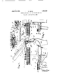
- FIG. 1 is a fragmentary side elevation of a ressing machine embodying my invention.
- igure 2 is a diagrammatic view of the means for controlling the head of the ma- 9 chine.
- the pressing machine may be of any de sired ;form,'size and construction.
- the yoke 5 is actuated through suitable power mechanism, which also is well known to those skilled in the art, and this power mechanism is actuated by a fluid m tor, that is a motor operated pre erably by compressed air, and the flow of air is controlled by a manually operated valve.
- a fluid m tor that is a motor operated pre erably by compressed air
- the flow of air is controlled by a manually operated valve.
- the motor which is operated by compressed air, includes a cylinder 8 the piston of which is connected to motion transmitting mechanism connected to the yoke 5 in any well known manner.
- the means for controlling the actuation of the head includes a conduit 12 for a motive fluid as compressed air, a normally closed intake valve 13 located in a casing 14 connected in said conduit 12, the casin being connected through a pipe 15 to the cylinder 8.
- a normally 0 en exhaust valve 16 is combined with the intake valve 13 to move as a unit therewith, it bein connected thereto by a stem 18 extending t rough the casing 14.
- This exhaust valve is movable into engagement with a seat 19.
- the valve 13 is acted upbn by a spring 20 acting to press it towards its seat 21, and normally hold it in closed position, and hold the exhaust valve 16 away from its seat or in open position.
- the intake and exhaust valves are operated by means of a handle or lever 22, which when depressed presses against the stem of the exhaust valve 16 closing the exhaust valve and opening the intake valve 13 so that the air can pass from the main line 12 through the valve casing 14 and the pipe 15 to the cylinder.
- the lever 22 is held depressed after the piston has moved through its power stroke by back .pressure through a pipe 23 to a diaphragm chamber 24, the diaphragm in the chamber acting upon the lever 22 to hold the exhaust valve 16 closed in the conventional manner.
- the exhaust valve is opened by moving the diaphragm manually but as the manual controls, the pipe 23, diaphragm chamber 24, and lever 22 forms no part of this invention further description is thought to be unnecessary.
- valve 27 is an exhaust valve casing mounted on the frame and having a movable valve 28 therein normally in closed position and pressed toward closed position by a spring 29.
- a pipe 30 connects the valve casing 27 to the feed line to cut out the intake valve 13 so that when the valve 28 is open the air will pass through the ipe 30 and out through the outlet 31 instea of passing from the valve 14 to the cylinder through the pipe 15. Hence when the valve 28 is open the press head will not continue its closing movement.
- the opening of the valve 28 is controlled by the relative movement of the guard 9 and head 4 and such relative movement is communicated to the valve through mechanism includin parts arranged concentric with the axis 6 o the support or yoke 5.
- connections as here shown include an arm 32 extending downwardly from the pivot 11 of the guard 9 and having a slot 33 for receiving a pin 34 at the upper end of a lever 35 pivoted between its ends at 36 to the frame, and having its inner end arranged to press against the stem 37 of the valve 28, the pin 34 being located substantially at the axis of the yoke 5.
- a pressing machine comprising a frame, a buck mounted on the frame, a head movable toward and from the buck, a pivoted supporting lever for the head, a guard ,carried by the head and normally movable as a unit therewith, means for controlling the actuation of the head including a conduit for a motive fluid, a normally closed intake valve in the conduit, manual means for opening the valve, a second normallv closed exhaust valve connected in said conduit to cut out the intake valve upon relative movement of the guard and the head and connections between the guard and the second valve, said connections including portions arranged concentric with the axis of the supporting lever for the head.
- a pressing machine comprising a frame, a buck mounted on the frame, a head movable toward and from the buck, a pivoted supporting lever for the head, a guard carried b the head and normally movable as a unit t erewith, and connected to the head to permit relative movement of the head and guard, means for controlling the actuation of the head including a conduit for a motive fluid, a normally closed intake valve in the conduit, manual means for opening the valve, a second normally closed exhaust valve connected in said conduit to cut out the intake valve upon relative movement of the guard and the head and connections between the guard and the valve, said connections including a lever pivoted to the frame and having one end coacting with the second valve to open it and its other end arranged concentric with the axis of the supporting lever for the head and the guard being pivoted to the said supporting lever and having an arm coactin with the second mentioned lever substantially at the axis of said support.
- a pressing machine comprising a frame, a buck mounted on the frame, a head movable toward and from the buck, a pivoted supporting lever for the head, a guard carried by the head and normally movable as a unit therewith and mounted to permit relative movement of the head and the guard, means for controlling the actuation of the head including a conduit for a motive fluid, a normally closed intake valve in the conduit, manual means for opening the valve, a second normally closed exhaust valve, connected in said conduit to cut out the intake valve upon relative movement of the guard and the head and connections between the guard and the valve, said connections including a lever pivoted to the frame and having one end coacting with the second named valve to open it and its other end arranged concentric with the axis of the supporting lever for the head and the guard being pivoted to the said supporting lever and having an arm meeting with the second lever substantially at the axis of said su porting lever, the arm of the second lever oing connected by a pin and slot, the pin of which is normally located concentric with the axi
- a buck a head movable toward and from the buck, means for controlling the actuation of the head including a conduit for a fluid, a normally closed valve in the conduit, manual means for opening the valve, a guard carried by the head and normally movable as a unit therewith, a second normally closed valve connected in the conduit and connectin links between the guard and the second va V8 for transmitting motion of the guard, relative to the head, to said second valve to operate the same.
- a buck a head movable toward and from the buck, manual means for controlling the actuation of the mucosa head including a conduit for a fluid, a normally closed intake valve in said conduit, head including a conduit for a fluid, a normally closed exhaust valve connected in said 5 conduit, a" guard carried by the head and normally movable as a unit therewith, and connections operated by the relative movement of the ard and the head to positively open the ex aust valve when the guard is m moved relatively to the head.
- a buck a head movable toward and from the buck, means for controlling the actuation of the head including a conduit for a motive fluid, it normally closed valve in the conduit, manual means for opening the valve, a guard carried by the head and normally movable as a unit therewith, means to prevent the effective flow of motive fluid' through the conduit, and
- mucosa head including a conduit for a fluid, a normally closed intake valve in said conduit, head including a conduit for a fluid, a normally closed exhaust valve connected in said 5 conduit, a" guard carried by the head and normally movable as a unit therewith, and connections operated by the relative movement of the ard and the head to positively open the ex aust valve when the guard is m moved relatively to the head.
- a buck a head movable toward and from the buck, means for controlling the actuation of the head including a conduit for a motive fluid, it normally closed valve in the conduit, manual means for opening the valve, a guard carried by the head and normally movable as a unit therewith, means to prevent the effective flow of motive fluid' through the conduit, and
Landscapes
- Engineering & Computer Science (AREA)
- Textile Engineering (AREA)
- Mechanically-Actuated Valves (AREA)
Description
April 19, 1932. DAV|$ 1,854,888
CONTROLLING MECHANISM FOR PRESSING MACHINES Original Filed April 14, 1926 Q INVENTOR. v 6,! ,UW
W ATTORNEYs,
Patented Apr. 19, 1932 PATENT OFFICE ERNEST DAVIS, O! SYRACUSE, NEWi YORK, ASSIGNOB TO THE PROSPERITY OOHPANY INQ, OF SYRACUSE, NEW YORK, A CORYOBATION NEW YORK comonnmo mncmrsm Application filed April 14, ms, semu This invention relates to pressing machines, particularly garment and laundry pressing machines which are actuated by a motive fluid as steam or air, and has for its object means for cutting out or rendering inefiective the motive fluid, which means is controlled by a guard movable by an obstruction in the path of the guard.
The invention consists in the novel features 19 and in the combinations and constructions hereinafter set forth and claimed.
In describing this invention reference is had to the accompanying drawings in which like characters designate corresponding parts in all the views.
Figure 1 is a fragmentary side elevation of a ressing machine embodying my invention. igure 2 is a diagrammatic view of the means for controlling the head of the ma- 9 chine.
permitting relative movement of the head and the guard when the guard is retarded in its movement,-means for controlling the actuation of the head including a conduit for a motive fluid as air, a normally closed intake valve in the conduit, manual means for opening the valve, a normally closed exhaust valve connected in said conduit to cut out the effective supply of fluid from the intake valve when t e guard is moved relatively to the head and connections operated by the guard to open the exhaust valve.
The pressing machine may be of any de sired ;form,'size and construction.
1 designates the buck, which is mounted upon a suitable bracket 2, which in turn is mounted upon a frame or table 3.
4 is the head movable toward and from the buck, it being here shown as carried by a yoke or supporting lever 5 pivoted at 6 to a standard 7 rising from the frame.
pivoted at 11 to the yo FOB PRESSING MACHINES No. 102,001. Renewed Kay 17, 1830.
This construction of a pressing machine is old and well known. The yoke 5 is actuated through suitable power mechanism, which also is well known to those skilled in the art, and this power mechanism is actuated by a fluid m tor, that is a motor operated pre erably by compressed air, and the flow of air is controlled by a manually operated valve. In the machine here illustrated the motor, which is operated by compressed air, includes a cylinder 8 the piston of which is connected to motion transmitting mechanism connected to the yoke 5 in any well known manner.
9 is a guard carried by the head and normally movable as a unit therewith, it being also capable of movement relatively to the yoke or head if an obstruction is encountered durin closing of the press. The guard is here s own as carried byxa s5upporting arm 10 The means for controlling the actuation of the head includes a conduit 12 for a motive fluid as compressed air, a normally closed intake valve 13 located in a casing 14 connected in said conduit 12, the casin being connected through a pipe 15 to the cylinder 8.
A normally 0 en exhaust valve 16 is combined with the intake valve 13 to move as a unit therewith, it bein connected thereto by a stem 18 extending t rough the casing 14. This exhaust valve is movable into engagement with a seat 19. The valve 13 is acted upbn by a spring 20 acting to press it towards its seat 21, and normally hold it in closed position, and hold the exhaust valve 16 away from its seat or in open position. The intake and exhaust valves are operated by means of a handle or lever 22, which when depressed presses against the stem of the exhaust valve 16 closing the exhaust valve and opening the intake valve 13 so that the air can pass from the main line 12 through the valve casing 14 and the pipe 15 to the cylinder. The lever 22 is held depressed after the piston has moved through its power stroke by back .pressure through a pipe 23 to a diaphragm chamber 24, the diaphragm in the chamber acting upon the lever 22 to hold the exhaust valve 16 closed in the conventional manner. The exhaust valve is opened by moving the diaphragm manually but as the manual controls, the pipe 23, diaphragm chamber 24, and lever 22 forms no part of this invention further description is thought to be unnecessary.
27 is an exhaust valve casing mounted on the frame and having a movable valve 28 therein normally in closed position and pressed toward closed position by a spring 29. A pipe 30 connects the valve casing 27 to the feed line to cut out the intake valve 13 so that when the valve 28 is open the air will pass through the ipe 30 and out through the outlet 31 instea of passing from the valve 14 to the cylinder through the pipe 15. Hence when the valve 28 is open the press head will not continue its closing movement. The opening of the valve 28 is controlled by the relative movement of the guard 9 and head 4 and such relative movement is communicated to the valve through mechanism includin parts arranged concentric with the axis 6 o the support or yoke 5.
These connections as here shown include an arm 32 extending downwardly from the pivot 11 of the guard 9 and having a slot 33 for receiving a pin 34 at the upper end of a lever 35 pivoted between its ends at 36 to the frame, and having its inner end arranged to press against the stem 37 of the valve 28, the pin 34 being located substantially at the axis of the yoke 5.
Obviously when the press is being closed by power due to the operator depressmg'the lever 22 to open the intake valve 13, if the guard 9 engages an obstruction as the hand of the operator so that the guard cannot continue its movement as a unit with the head, the relative movement of the head and the guard will cause the lever 35 to be actuated and thus open the valve 27 so that the motive fluid instead of flowin to the cylinder 15 to finally close the press cad will escape through the valve casing 27.
What I claim is:
1. A pressing machine comprising a frame, a buck mounted on the frame, a head movable toward and from the buck, a pivoted supporting lever for the head, a guard ,carried by the head and normally movable as a unit therewith, means for controlling the actuation of the head including a conduit for a motive fluid, a normally closed intake valve in the conduit, manual means for opening the valve, a second normallv closed exhaust valve connected in said conduit to cut out the intake valve upon relative movement of the guard and the head and connections between the guard and the second valve, said connections including portions arranged concentric with the axis of the supporting lever for the head.
2. A pressing machine comprising a frame, a buck mounted on the frame, a head movable toward and from the buck, a pivoted supporting lever for the head, a guard carried b the head and normally movable as a unit t erewith, and connected to the head to permit relative movement of the head and guard, means for controlling the actuation of the head including a conduit for a motive fluid, a normally closed intake valve in the conduit, manual means for opening the valve, a second normally closed exhaust valve connected in said conduit to cut out the intake valve upon relative movement of the guard and the head and connections between the guard and the valve, said connections including a lever pivoted to the frame and having one end coacting with the second valve to open it and its other end arranged concentric with the axis of the supporting lever for the head and the guard being pivoted to the said supporting lever and having an arm coactin with the second mentioned lever substantially at the axis of said support.
3. A pressing machine comprising a frame, a buck mounted on the frame, a head movable toward and from the buck, a pivoted supporting lever for the head, a guard carried by the head and normally movable as a unit therewith and mounted to permit relative movement of the head and the guard, means for controlling the actuation of the head including a conduit for a motive fluid, a normally closed intake valve in the conduit, manual means for opening the valve, a second normally closed exhaust valve, connected in said conduit to cut out the intake valve upon relative movement of the guard and the head and connections between the guard and the valve, said connections including a lever pivoted to the frame and having one end coacting with the second named valve to open it and its other end arranged concentric with the axis of the supporting lever for the head and the guard being pivoted to the said supporting lever and having an arm meeting with the second lever substantially at the axis of said su porting lever, the arm of the second lever oing connected by a pin and slot, the pin of which is normally located concentric with the axis of said supporting lever. I
4. In a pressing machine, a buck, a head movable toward and from the buck, means for controlling the actuation of the head including a conduit for a fluid, a normally closed valve in the conduit, manual means for opening the valve, a guard carried by the head and normally movable as a unit therewith, a second normally closed valve connected in the conduit and connectin links between the guard and the second va V8 for transmitting motion of the guard, relative to the head, to said second valve to operate the same.
5. Ina pressing machine a buck, a head movable toward and from the buck, manual means for controlling the actuation of the mucosa head including a conduit for a fluid, a normally closed intake valve in said conduit, head including a conduit for a fluid, a normally closed exhaust valve connected in said 5 conduit, a" guard carried by the head and normally movable as a unit therewith, and connections operated by the relative movement of the ard and the head to positively open the ex aust valve when the guard is m moved relatively to the head.
6. In a pressing machine, a buck, a head movable toward and from the buck, means for controlling the actuation of the head including a conduit for a motive fluid, it normally closed valve in the conduit, manual means for opening the valve, a guard carried by the head and normally movable as a unit therewith, means to prevent the effective flow of motive fluid' through the conduit, and
20 connections between said last mentioned means and the guard for transmitting movement of the guard, relative to the head, to said last mentioned means.
In testimony whereof, I have hereunto 35 signed my name, at Syracuse, in the county of Onondaga and in the State of New York, this 6th day of April, 1926.
ERNEST DAVIS.
CERTIFICATE OF CORRECTION.
Patent No. 1,854,888. April 19, 1932.
ERNEST DAVIS.
It. is hereby certified that error appears in the printed specification of the above numbered patent requiring correction as follows: Page 2, line 15, after the word "valve" insert the word casing, and line 29, for "inner" read lower; page 3, line 3, claim 5, strike out the words "head including a conduit for a fluid" and insert instead means for opening the intake valve; and that the said Letters Patent should be read with these corrections therein that the same may conform to the record of the case in the Patent Office.
Signed and sealed this 12th day of July, A. D. 1932.
M. J. Moore, Acting Commissioner of Patents.
mucosa head including a conduit for a fluid, a normally closed intake valve in said conduit, head including a conduit for a fluid, a normally closed exhaust valve connected in said 5 conduit, a" guard carried by the head and normally movable as a unit therewith, and connections operated by the relative movement of the ard and the head to positively open the ex aust valve when the guard is m moved relatively to the head.
6. In a pressing machine, a buck, a head movable toward and from the buck, means for controlling the actuation of the head including a conduit for a motive fluid, it normally closed valve in the conduit, manual means for opening the valve, a guard carried by the head and normally movable as a unit therewith, means to prevent the effective flow of motive fluid' through the conduit, and
20 connections between said last mentioned means and the guard for transmitting movement of the guard, relative to the head, to said last mentioned means.
In testimony whereof, I have hereunto 35 signed my name, at Syracuse, in the county of Onondaga and in the State of New York, this 6th day of April, 1926.
ERNEST DAVIS.
CERTIFICATE OF CORRECTION.
Patent No. 1,854,888. April 19, 1932.
ERNEST DAVIS.
It. is hereby certified that error appears in the printed specification of the above numbered patent requiring correction as follows: Page 2, line 15, after the word "valve" insert the word casing, and line 29, for "inner" read lower; page 3, line 3, claim 5, strike out the words "head including a conduit for a fluid" and insert instead means for opening the intake valve; and that the said Letters Patent should be read with these corrections therein that the same may conform to the record of the case in the Patent Office.
Signed and sealed this 12th day of July, A. D. 1932.
M. J. Moore, Acting Commissioner of Patents.
Priority Applications (1)
| Application Number | Priority Date | Filing Date | Title |
|---|---|---|---|
| US102001A US1854888A (en) | 1926-04-14 | 1926-04-14 | Controlling mechanism for pressing machines |
Applications Claiming Priority (1)
| Application Number | Priority Date | Filing Date | Title |
|---|---|---|---|
| US102001A US1854888A (en) | 1926-04-14 | 1926-04-14 | Controlling mechanism for pressing machines |
Publications (1)
| Publication Number | Publication Date |
|---|---|
| US1854888A true US1854888A (en) | 1932-04-19 |
Family
ID=22287591
Family Applications (1)
| Application Number | Title | Priority Date | Filing Date |
|---|---|---|---|
| US102001A Expired - Lifetime US1854888A (en) | 1926-04-14 | 1926-04-14 | Controlling mechanism for pressing machines |
Country Status (1)
| Country | Link |
|---|---|
| US (1) | US1854888A (en) |
Cited By (5)
| Publication number | Priority date | Publication date | Assignee | Title |
|---|---|---|---|---|
| US2642973A (en) * | 1946-11-16 | 1953-06-23 | Bata Narodni Podnik | Pressing and like machine |
| US3333355A (en) * | 1965-04-09 | 1967-08-01 | Ametek Inc | Combined safety and exhaust hood for pressing machine |
| DE1254573B (en) * | 1963-06-08 | 1967-11-23 | Constructa Werke G M B H | Ironing press |
| DE1259828B (en) * | 1963-06-08 | 1968-02-01 | Constructa Werke G M B H | Safety device for an ironing machine with a heated ironing plate |
| DE1585554B1 (en) * | 1965-04-09 | 1971-12-23 | Ametek Inc | Safety and suction hood for ironing presses |
-
1926
- 1926-04-14 US US102001A patent/US1854888A/en not_active Expired - Lifetime
Cited By (5)
| Publication number | Priority date | Publication date | Assignee | Title |
|---|---|---|---|---|
| US2642973A (en) * | 1946-11-16 | 1953-06-23 | Bata Narodni Podnik | Pressing and like machine |
| DE1254573B (en) * | 1963-06-08 | 1967-11-23 | Constructa Werke G M B H | Ironing press |
| DE1259828B (en) * | 1963-06-08 | 1968-02-01 | Constructa Werke G M B H | Safety device for an ironing machine with a heated ironing plate |
| US3333355A (en) * | 1965-04-09 | 1967-08-01 | Ametek Inc | Combined safety and exhaust hood for pressing machine |
| DE1585554B1 (en) * | 1965-04-09 | 1971-12-23 | Ametek Inc | Safety and suction hood for ironing presses |
Similar Documents
| Publication | Publication Date | Title |
|---|---|---|
| US1854888A (en) | Controlling mechanism for pressing machines | |
| US2050619A (en) | Press operating mechanism | |
| US2065235A (en) | Pressing machine | |
| US2023895A (en) | Press control mechanism | |
| US1641131A (en) | Garment-pressing machine | |
| US1972474A (en) | Garment or ironing press | |
| US1902018A (en) | Actuating mechanism for pressing machines | |
| US2022176A (en) | Pressing machine and element | |
| US1609273A (en) | Pneumatic control and safety device for pressing machines | |
| US2045446A (en) | Actuating mechanism for pressing machines | |
| US1890341A (en) | Pressing machine | |
| US1940642A (en) | Automatic double buck press | |
| US1335835A (en) | Control mechanism for pressing-machines | |
| US1817344A (en) | Pressing machine (work holding means) | |
| US2023896A (en) | Pressing machine | |
| US2198224A (en) | Press control mechanism | |
| US1874697A (en) | Automatic pressure locking means | |
| US2045448A (en) | Pressing machine | |
| US1928753A (en) | Ironing press and neck band holder | |
| US2171559A (en) | Control mechanism for pressing machines | |
| US2788769A (en) | Air operated garment press having two different pressing pressures | |
| US2045447A (en) | Garment or ironing press | |
| US1949115A (en) | Garment or ironing press | |
| US2323134A (en) | Semipower press and tandem control | |
| US1670763A (en) | Power mechanism for pressing machines |