US1854819A - Apparatus for generating combustible gas - Google Patents
Apparatus for generating combustible gas Download PDFInfo
- Publication number
- US1854819A US1854819A US404017A US40401729A US1854819A US 1854819 A US1854819 A US 1854819A US 404017 A US404017 A US 404017A US 40401729 A US40401729 A US 40401729A US 1854819 A US1854819 A US 1854819A
- Authority
- US
- United States
- Prior art keywords
- liquid
- air
- orifice
- pipe
- tank
- Prior art date
- Legal status (The legal status is an assumption and is not a legal conclusion. Google has not performed a legal analysis and makes no representation as to the accuracy of the status listed.)
- Expired - Lifetime
Links
- 239000007788 liquid Substances 0.000 description 58
- 230000008878 coupling Effects 0.000 description 5
- 238000010168 coupling process Methods 0.000 description 5
- 238000005859 coupling reaction Methods 0.000 description 5
- 230000015572 biosynthetic process Effects 0.000 description 4
- 238000010276 construction Methods 0.000 description 3
- 238000009834 vaporization Methods 0.000 description 3
- 230000008016 vaporization Effects 0.000 description 3
- OFBQJSOFQDEBGM-UHFFFAOYSA-N Pentane Chemical compound CCCCC OFBQJSOFQDEBGM-UHFFFAOYSA-N 0.000 description 2
- 230000001419 dependent effect Effects 0.000 description 2
- 230000008020 evaporation Effects 0.000 description 2
- 238000001704 evaporation Methods 0.000 description 2
- 239000000945 filler Substances 0.000 description 2
- 230000008014 freezing Effects 0.000 description 2
- 238000007710 freezing Methods 0.000 description 2
- 230000004048 modification Effects 0.000 description 2
- 238000012986 modification Methods 0.000 description 2
- 210000002445 nipple Anatomy 0.000 description 2
- 238000007789 sealing Methods 0.000 description 2
- LFQSCWFLJHTTHZ-UHFFFAOYSA-N Ethanol Chemical compound CCO LFQSCWFLJHTTHZ-UHFFFAOYSA-N 0.000 description 1
- 238000005520 cutting process Methods 0.000 description 1
- 230000007423 decrease Effects 0.000 description 1
- 238000007599 discharging Methods 0.000 description 1
- 230000003116 impacting effect Effects 0.000 description 1
- 238000009434 installation Methods 0.000 description 1
- 239000003350 kerosene Substances 0.000 description 1
- 238000004519 manufacturing process Methods 0.000 description 1
- 238000000034 method Methods 0.000 description 1
- 239000002245 particle Substances 0.000 description 1
- 230000002093 peripheral effect Effects 0.000 description 1
- 230000002265 prevention Effects 0.000 description 1
- 230000000135 prohibitive effect Effects 0.000 description 1
- 238000003860 storage Methods 0.000 description 1
Images
Classifications
-
- C—CHEMISTRY; METALLURGY
- C10—PETROLEUM, GAS OR COKE INDUSTRIES; TECHNICAL GASES CONTAINING CARBON MONOXIDE; FUELS; LUBRICANTS; PEAT
- C10J—PRODUCTION OF PRODUCER GAS, WATER-GAS, SYNTHESIS GAS FROM SOLID CARBONACEOUS MATERIAL, OR MIXTURES CONTAINING THESE GASES; CARBURETTING AIR OR OTHER GASES
- C10J1/00—Production of fuel gases by carburetting air or other gases without pyrolysis
Definitions
- This invention relates to improvements in a carbureter designed particularly for use in the generation of a combustible gas by the intimate association of air with a combusti-
- One of the important objects of the present invention resides in the provision of means for intimately associating combustible liquid with air in such a manner. as to generate a 1 substantially uniform and constant B. t. u. content gas.
- the capacity of the device can be feasibly raised to the point where a consumers maximum demand can be met without increasing the size of the generator to prohibitive proportions.
- Another salient feature comprises the novel disposition of the instrumentalities of which the carbureter consists which results in establishing a stream of combustible liquid and a stream of air both under pressure, the two streams being adapted to intersect and combine at an angle, the pressure necessary for the establishment of both streams being obtained from one source.
- the invention comprises a main cylinder adapted to be vertically disposed ,in an enclosed tank, the tank functioning as a container for a main bulk supply of combustible liquid.
- the bottom of the cylinder may be closed, while the top may be connected to an upstanding pipe through which air under pressure may be introduced from a blower or the like external of the tank.
- a check valve may be provided adjacent the lower end of the cylind-erto permit a one- Way flow of liquid from the tank to the cylinder whenever the tank pressure exceeds the cylinder pressure.
- a comparatively small sectioned pipe may also be connected to the lower portion of the cylinder, the discharge end thereof terminating adjacent an orifice provided in the first mentioned upstanding pipe at the top of the cylinder.
- the small sectioned pipe will hereinafter be referred to as the liquid pipe, whereas the orifice above mentioned will be referred to as the air orifice.
- The. discharge of the liquid pipe is, preferably disposed above the axis of the air ori- 1, 1929. Serial No. 404,017.
- Another feature of the present invention directed to the prevention of the sealing of the air orifice by the freezing of moisture entrained in the air stream comprises a knife edge construction of the periphery of the air' orifice. It is substantially mechanically impossible for an appreciable ice film or formation to build upon so thin a foundation.
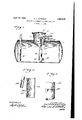
- Fig. 1 is a sectional side elevation of'the tank, showing particularly the disposition of the oarbureter therein.
- Fig. 2 is a fragmentary detail sectional view of the air orifice and liquid discharge plpe.
- Fig. 3 is an elevational view of a modified form of air orifice.
- 1 indicates generally a tank or closed container provided with a turret or manhead 2 closed by a cover plate 3 fastened to the manhead by means of bolts or the like 4i.
- the tank 1 is 109 also provided with a filler pipe 5 which projects downwardly to substantially the center of the tank, which pipe may be provided with a screen 6.
- a cylindrical coupling 7 is welded or otherwise suitably secured in an opening provided in the side of the turret 2.
- a bushing 8 is positioned in the coupling 7 and is adapted to receive a pipe 9 through which air under pressure may be delivered.
- a nipple 10 which virtually comprises a continuation of the line 9 within the turret, connects a bushing 11 positioned within the coupling 7 to a T coupling 12, which in turn is mounted upon the upper end of a pipe 13, comprising a portion of the carbureter proper.
- a union 14 may be interposed in the pipe 13 to facilitate the connecting and disconnecting of the various lines.
- the lower end of the pipe 18 is threadedly, or otherwise suitably connected to the top of an enclosed cylinder 15, preferably of larger diameter than the pipe 13.
- a one way inlet or check valve 16 may be provided at the lower portion of the cylinder 15 and is adapted to be disposed below the liquid level of the tank 1. It is apparent that whenever the pressure outside the valve 16, that is, the tank pressure, is greater than the pressure within the cylinder 15, that is, the pressure established in line 9, or the blower pressure as the same will hereinafter be referred to, liquid will enter the cylinder from the tank through said valve.
- an outlet in which an elbow 17 is positioned in which an elbow 17 is positioned. The other end of the elbow is connected to a pipe 18 of comparatively restricted diameter which may extend upwardly to the top of the carbureter proper and then double back adjacent the pipe 13, as shown.
- An orifice 19 may be provided in the side of the pipe 13 adjacent the discharge end of the pipe 18. I have found it advantageous, for reasons to be hereinafter brougat out, to position the discharge end of the pipe 18 a slight distance away from the pipe 13, say from one-half to two or two and one-half inches, more or less, but I do not wish to be limited to these specific distances, inasmuch as the distance is dependent upon various fac tors, all of which are controlling. Liquid from the cylinder 15 is adapted to be forced through the pipe 18 and discharged adjacent the orifice 19 from which a blast of air issues. A vapor or fog is thus formed within the tank, and due to the rapid vaporization, the temperature in the vicinity of the point at which this vaporization takes place is greatly reduced.
- the arm of the T coupling 12 opposite the nipple 10 may have operatively connected thereto a check valve 21, provided for several purposes, all of which contribute to the safe automatic operation of the apparatus. For instance, assume that the pipe line 9 is accidentally opened while gas pressure exists in the tank, and further assume that the valve 21 is not provided. A difference of pressure will then exist on the surfaces of the liquid in the tank and in the cylinder.
- liquid will flow from the tank to the" cylinder, inasmuch as the tank pressure will be the greater, and the liquid will flew back through the pipe 9.
- gas will escape from the tank to the pipe 13 through the orifice 19, and tend to equalize the pressures on the cylinder liquid and the tank liquid but, due to the relatively small area of the orifice, the liquid in the cylinder will rise above the orifice before this equilibrium can be established.
- the valve 21' By placing the valve 21' in the system, the gas pressure in the tank will immediately be relieved before the liquid in the cylinder rises. Hence, undesirable back flow of liquid fromthe tank toward the point of gas consumption will be auto-'- matically eliminated.
- a quantity of combustible liquid such as gasoline, kerosene, alcohol, pentane or the like, may be charged to tank 1 through filler pipe 5, until a desirable level V is reached, for instance, half full. Liquid will flow from the tank 1 into the cylinder 15 through the valve 16 until the liquid in the cylinder has assumed the level of the 7 liquid in the tank. Air under pressure may then be introduced through the pipe 9, and a blast of air will issue from the orifice 19 in the pipe 13 but, due to the restricted area of the orifice, a pressure will be established in the cylinder 15 above the liquid contained therein. Both check valves 16 and 21 will be closed due to the greater pressure within the carburetor. Hence, the only efiect of this pressure will be to force a streamof liquid from the cylinder 15 through the pipe 18,
- the air introduced through the pipe 9 may be stopped preferably by some suitable automatic means (not shown) whereupon the pressure within the cylinder 15 will be equal to the tank pressure, the valve 16 will open and the liquid level in the cylinder will again raise to the level of the tank liquid.
- automatic means (not shown) may be resorted to to again supply air and generate more gas. This procedure may continue until the liquid in the tank is substantially exhausted.
- FIG. 3 A slight modification of the air orifice is shown in Fig. 3, wherein the numeral 13 corresponds to the pipe 13.
- an orifice 19 is provided in the pipe 13 and may be of an elongated cross section, characterized by being long and narrow. It'is obvious that the stream of air issuing from the opening 19 will assume the form of a wide but thin ribbon, hence vaporization will be assisted and the capacity of the device increased, other things being equal.
- a carbureter for a gas producing machine comprising in combination, a container for combustible liquid, an air inlet and a liquid outlet connected to the container, said air inlet being provided with an orifice, the defining edge of which is relatively thin, the discharge end of the liquid outlet being positioned adjacent the path of the stream of air issuing from the orifice and removed a relatively slight distance from the orifice,
- an enclosed vessel adapted to contain a combustible liquid
- an air inlet connected to the vessel
- a carbureter disposed within the vessel and connected with the air inlet, said carbureter being provided with means above the liquid level in the vesselfor preventing the liquid in the vessel from flowing through the air inlet.
- a carburetor for a gas generating machine comprising, in combination, an enclosed vessel for containing a bulk supply of combustible liquid, a container disposed within the vessel, an air inlet into said container, said air inlet being provided with an orifice adapted to permit a limited discharge of air therefrom, a liquid inlet into said container closed when the pressure within the container is greater than the vessel pressure, a liquid outlet from said container disposed within said vessel and above the surface of the liquid therein, said liquid outlet being positioned adjacent the stream of air issuing from the orifice and adapted to direct liquid from the container into the stream of air.
- a carburetor for a gas generating machine comprising, in combination, an enclosed vessel for containing a bulk supply of combustible liquid, a container disposed within the vessel, an air inlet into said container, said air inlet being provided with an orifice adapted to permit a limited discharge of air therefrom, a liquid inlet into said container closed when the pressure within the container is greater than the vessel pressure, a liquid outlet from said container disposed within said vessel and above the surface of the liquid therein, said liquid outlet being positioned adjacent the stream of air issuing from the orifice and adapted to direct liquid from the container into the stream of air, said container being provided with means above the liquid level in the vessel and preventing the liquid in the vessel from flowing through the air inlet.
- an enclosed vessel adapted to contain a combustible liquid
- an air inlet connected to the vessel
- a carburetor disposed within the vessel and connected with the air inlet
- said carburetor being provided with means above the liquid level in the vessel for preventing the liquid in the vessel from flowing through the air inlet
- said means comprising a check valve connected to the air in let to the carburetor and being adapted to open when the pressure within the vessel exceeds the pressure within the carburetor.
Landscapes
- Chemical & Material Sciences (AREA)
- Engineering & Computer Science (AREA)
- Combustion & Propulsion (AREA)
- Oil, Petroleum & Natural Gas (AREA)
- Organic Chemistry (AREA)
- Filling Or Discharging Of Gas Storage Vessels (AREA)
Description
-. gyble liquid.
Patented Apr. 19, 1932 UNITED STATES PATENT OFFICE CARL OTTO WANNACK, OF CHICAGO, ILLINOIS, ASSIGNOR, BY MESN E ASSIGNMENTS, TO
S. H. G. INCORPORATED, OF CHICAGO, ILLINOIS, A CORPORATION OF DELAWARE APPARATUS FOR GENERATING COMBUSTIBLE GAS Application filed November This invention relates to improvements in a carbureter designed particularly for use in the generation of a combustible gas by the intimate association of air with a combusti- One of the important objects of the present invention resides in the provision of means for intimately associating combustible liquid with air in such a manner. as to generate a 1 substantially uniform and constant B. t. u. content gas. As a feature of the invention, the capacity of the device can be feasibly raised to the point where a consumers maximum demand can be met without increasing the size of the generator to prohibitive proportions.
Another salient feature comprises the novel disposition of the instrumentalities of which the carbureter consists which results in establishing a stream of combustible liquid and a stream of air both under pressure, the two streams being adapted to intersect and combine at an angle, the pressure necessary for the establishment of both streams being obtained from one source.
Briefly described the invention comprises a main cylinder adapted to be vertically disposed ,in an enclosed tank, the tank functioning as a container for a main bulk supply of combustible liquid. The bottom of the cylinder may be closed, while the top may be connected to an upstanding pipe through which air under pressure may be introduced from a blower or the like external of the tank.
A check valve may be provided adjacent the lower end of the cylind-erto permit a one- Way flow of liquid from the tank to the cylinder whenever the tank pressure exceeds the cylinder pressure. A comparatively small sectioned pipe may also be connected to the lower portion of the cylinder, the discharge end thereof terminating adjacent an orifice provided in the first mentioned upstanding pipe at the top of the cylinder. The small sectioned pipe will hereinafter be referred to as the liquid pipe, whereas the orifice above mentioned will be referred to as the air orifice. The. discharge of the liquid pipe is, preferably disposed above the axis of the air ori- 1, 1929. Serial No. 404,017.
fice for reasons to be hereinafter more fully explained.
It is a wellknown physical fact that rapid evaporation or volatilization of a liquid is endothermic, that is, heat is absorbed from the medium in the vicinity of the point of evaporation or volatilization and the temperature thereabo-ut is considerably lowered.
I have found that, by spacing the discharge end of the liquid pipe a slight distance from the air orifice, the point where volatilization takes place, that is, the point of impact between the two streams, is sufiiciently removed from the air orifice to prevent freezing of entrained moisture carried by the air at the orifice, and hence, sealing of the air orifice by a formation of ice orsnow is prevented. The distance the discharge of the liquid pipe is to be placed relative to the air orifice is dependent upon various factors, among which may be mentioned the geometrical proportions of the carbureter; the velocities of the two impacting streams; the size of the air orifice; the quantity of moisture carried by the air, and other factors.
Another feature of the present invention directed to the prevention of the sealing of the air orifice by the freezing of moisture entrained in the air stream comprises a knife edge construction of the periphery of the air' orifice. It is substantially mechanically impossible for an appreciable ice film or formation to build upon so thin a foundation.
Other and further important features of the present invention will be apparent from the accompanying drawings and following detailed description. 1
In the drawings, Fig. 1 is a sectional side elevation of'the tank, showing particularly the disposition of the oarbureter therein.
Fig. 2 is a fragmentary detail sectional view of the air orifice and liquid discharge plpe.
Fig. 3 is an elevational view of a modified form of air orifice.
Referring in detail to the drawings, 1 indicates generally a tank or closed container provided with a turret or manhead 2 closed by a cover plate 3 fastened to the manhead by means of bolts or the like 4i. The tank 1 is 109 also provided with a filler pipe 5 which projects downwardly to substantially the center of the tank, which pipe may be provided with a screen 6.
A cylindrical coupling 7 is welded or otherwise suitably secured in an opening provided in the side of the turret 2. A bushing 8 is positioned in the coupling 7 and is adapted to receive a pipe 9 through which air under pressure may be delivered. A nipple 10, which virtually comprises a continuation of the line 9 within the turret, connects a bushing 11 positioned within the coupling 7 to a T coupling 12, which in turn is mounted upon the upper end of a pipe 13, comprising a portion of the carbureter proper. A union 14: may be interposed in the pipe 13 to facilitate the connecting and disconnecting of the various lines.
The lower end of the pipe 18 is threadedly, or otherwise suitably connected to the top of an enclosed cylinder 15, preferably of larger diameter than the pipe 13. A one way inlet or check valve 16 may be provided at the lower portion of the cylinder 15 and is adapted to be disposed below the liquid level of the tank 1. It is apparent that whenever the pressure outside the valve 16, that is, the tank pressure, is greater than the pressure within the cylinder 15, that is, the pressure established in line 9, or the blower pressure as the same will hereinafter be referred to, liquid will enter the cylinder from the tank through said valve. Provided, also, in the lower portion of the cylinder 15 at a point substantially diametrically opposite the valve 16 is an outlet, in which an elbow 17 is positioned. The other end of the elbow is connected to a pipe 18 of comparatively restricted diameter which may extend upwardly to the top of the carbureter proper and then double back adjacent the pipe 13, as shown.
An orifice 19 may be provided in the side of the pipe 13 adjacent the discharge end of the pipe 18. I have found it advantageous, for reasons to be hereinafter brougat out, to position the discharge end of the pipe 18 a slight distance away from the pipe 13, say from one-half to two or two and one-half inches, more or less, but I do not wish to be limited to these specific distances, inasmuch as the distance is dependent upon various fac tors, all of which are controlling. Liquid from the cylinder 15 is adapted to be forced through the pipe 18 and discharged adjacent the orifice 19 from which a blast of air issues. A vapor or fog is thus formed within the tank, and due to the rapid vaporization, the temperature in the vicinity of the point at which this vaporization takes place is greatly reduced. By disposing the discharge end of the pipe 18 a slight distance from the orifice 19, the tendency for any moisture carried by the air to freeze at the orifice is eliminated. I have also found that by cutting down the surface of the pipe 13, as shown best at 20 in Fig. 2, providing a very thin peripheral edge defining the orifice, it becomes mechanically impossible for a formation of ice to build upon the edge of the orifice, hence the air always has free exit from the orifice unobstructed by any ice formation. In addition, a knife edge orifice, as is well known decreases friction.
Although the discharge end of pipe 18 is shown and described as being above the orifice 19, as is preferable inasmuch as all the liquid discharged from the pipe 18 must, of necessity, passthrough the stream of air, the invention in its broadest aspects contemplates directing the liquid discharge past the orifice either from above or below, or from either side thereof. 7
The arm of the T coupling 12 opposite the nipple 10 may have operatively connected thereto a check valve 21, provided for several purposes, all of which contribute to the safe automatic operation of the apparatus. For instance, assume that the pipe line 9 is accidentally opened while gas pressure exists in the tank, and further assume that the valve 21 is not provided. A difference of pressure will then exist on the surfaces of the liquid in the tank and in the cylinder.
IIence, liquid will flow from the tank to the" cylinder, inasmuch as the tank pressure will be the greater, and the liquid will flew back through the pipe 9. Of course, gas will escape from the tank to the pipe 13 through the orifice 19, and tend to equalize the pressures on the cylinder liquid and the tank liquid but, due to the relatively small area of the orifice, the liquid in the cylinder will rise above the orifice before this equilibrium can be established. By placing the valve 21' in the system, the gas pressure in the tank will immediately be relieved before the liquid in the cylinder rises. Hence, undesirable back flow of liquid fromthe tank toward the point of gas consumption will be auto-'- matically eliminated.
In operation, a quantity of combustible liquid, such as gasoline, kerosene, alcohol, pentane or the like, may be charged to tank 1 through filler pipe 5, until a desirable level V is reached, for instance, half full. Liquid will flow from the tank 1 into the cylinder 15 through the valve 16 until the liquid in the cylinder has assumed the level of the 7 liquid in the tank. Air under pressure may then be introduced through the pipe 9, and a blast of air will issue from the orifice 19 in the pipe 13 but, due to the restricted area of the orifice, a pressure will be established in the cylinder 15 above the liquid contained therein. Both check valves 16 and 21 will be closed due to the greater pressure within the carburetor. Hence, the only efiect of this pressure will be to force a streamof liquid from the cylinder 15 through the pipe 18,
discharging the same at an angle to the axis of the stream of air issuing from the orifice 19, thus breaking up said stream into finely divided droplets or particles, and intimately 5 mixing the liquid and the air.
When the tank pressure reaches a certain desired value, for instance, four pounds to the square inch, the air introduced through the pipe 9 may be stopped preferably by some suitable automatic means (not shown) whereupon the pressure within the cylinder 15 will be equal to the tank pressure, the valve 16 will open and the liquid level in the cylinder will again raise to the level of the tank liquid. As gas is drawn from the tank through a gas outlet pipe 22 the pressure therein will be reduced, hence, if desired, when the tank pressure falls to a certain predetermined minimum say, for instance, one pound to the square inch, automatic means (not shown) may be resorted to to again supply air and generate more gas. This procedure may continue until the liquid in the tank is substantially exhausted.
A slight modification of the air orifice is shown in Fig. 3, wherein the numeral 13 corresponds to the pipe 13. In this embodiment an orifice 19 is provided in the pipe 13 and may be of an elongated cross section, characterized by being long and narrow. It'is obvious that the stream of air issuing from the opening 19 will assume the form of a wide but thin ribbon, hence vaporization will be assisted and the capacity of the device increased, other things being equal.
It is apparent that I have provided a device characterized by relative simplicity of operation and construction and capable of eificiently performing the function for which it is designed. The device is rugged and con tains no parts susceptible to being broken and inasmuch as it is adapted to be disposed within the gas storage tank and since said tank is totally enclosed, the danger incident to breaking or tampering with the carbureter is eliminated. The device, in addition, is comparatively economical to manufacture and is I certain to find a ready market, particularly for home installation.
I am aware that many modifications of the present construction may be devised without departing from the spirit of the invention, and hence I do not wish to be limited except as necessitated by the prior art.
I claim as my invention:
1. A carbureter for a gas producing machine, comprising in combination, a container for combustible liquid, an air inlet and a liquid outlet connected to the container, said air inlet being provided with an orifice, the defining edge of which is relatively thin, the discharge end of the liquid outlet being positioned adjacent the path of the stream of air issuing from the orifice and removed a relatively slight distance from the orifice,
adapted to direct liquid from the container into the stream of air.
2. In combination, an enclosed vessel adapted to contain a combustible liquid, an air inlet connected to the vessel, a carbureter disposed within the vessel and connected with the air inlet, said carbureter being provided with means above the liquid level in the vesselfor preventing the liquid in the vessel from flowing through the air inlet.
3. A carburetor for a gas generating machine comprising, in combination, an enclosed vessel for containing a bulk supply of combustible liquid, a container disposed within the vessel, an air inlet into said container, said air inlet being provided with an orifice adapted to permit a limited discharge of air therefrom, a liquid inlet into said container closed when the pressure within the container is greater than the vessel pressure, a liquid outlet from said container disposed within said vessel and above the surface of the liquid therein, said liquid outlet being positioned adjacent the stream of air issuing from the orifice and adapted to direct liquid from the container into the stream of air.
4. A carburetor for a gas generating machine comprising, in combination, an enclosed vessel for containing a bulk supply of combustible liquid, a container disposed within the vessel, an air inlet into said container, said air inlet being provided with an orifice adapted to permit a limited discharge of air therefrom, a liquid inlet into said container closed when the pressure within the container is greater than the vessel pressure, a liquid outlet from said container disposed within said vessel and above the surface of the liquid therein, said liquid outlet being positioned adjacent the stream of air issuing from the orifice and adapted to direct liquid from the container into the stream of air, said container being provided with means above the liquid level in the vessel and preventing the liquid in the vessel from flowing through the air inlet.
5. In combination, an enclosed vessel adapted to contain a combustible liquid, an air inlet connected to the vessel, a carburetor disposed within the vessel and connected with the air inlet, said carburetor being provided with means above the liquid level in the vessel for preventing the liquid in the vessel from flowing through the air inlet, said means comprising a check valve connected to the air in let to the carburetor and being adapted to open when the pressure within the vessel exceeds the pressure within the carburetor.
In testimony whereof I aflix my signature.
CARL OTTO WANNAGK.
Priority Applications (1)
| Application Number | Priority Date | Filing Date | Title |
|---|---|---|---|
| US404017A US1854819A (en) | 1929-11-01 | 1929-11-01 | Apparatus for generating combustible gas |
Applications Claiming Priority (1)
| Application Number | Priority Date | Filing Date | Title |
|---|---|---|---|
| US404017A US1854819A (en) | 1929-11-01 | 1929-11-01 | Apparatus for generating combustible gas |
Publications (1)
| Publication Number | Publication Date |
|---|---|
| US1854819A true US1854819A (en) | 1932-04-19 |
Family
ID=23597788
Family Applications (1)
| Application Number | Title | Priority Date | Filing Date |
|---|---|---|---|
| US404017A Expired - Lifetime US1854819A (en) | 1929-11-01 | 1929-11-01 | Apparatus for generating combustible gas |
Country Status (1)
| Country | Link |
|---|---|
| US (1) | US1854819A (en) |
-
1929
- 1929-11-01 US US404017A patent/US1854819A/en not_active Expired - Lifetime
Similar Documents
| Publication | Publication Date | Title |
|---|---|---|
| US2519618A (en) | Evaporator and fluid contact apparatus | |
| US2339640A (en) | Liquid carbonation | |
| US3106071A (en) | System for filling closed containers with volatile liquids | |
| US4426984A (en) | Apparatus for entraining gasoline in air for use in an internal combustion engine | |
| US1201558A (en) | Gasolene-separator. | |
| US1854819A (en) | Apparatus for generating combustible gas | |
| US2217841A (en) | Apparatus for carbonating water | |
| US2409611A (en) | Charge forming method and apparatus for internal-combustion engines | |
| US2335837A (en) | Apparatus for utilization of liquefied petroleum gases | |
| US641684A (en) | Means for carbonating liquids. | |
| US1220103A (en) | Device for projecting burning liquids. | |
| US2050514A (en) | Process for generating combustible gas | |
| US2043599A (en) | Device for producing foam | |
| US2511172A (en) | Pressure operated switch | |
| US1471705A (en) | Apparatus for treating fresh petroleum | |
| US2418184A (en) | Pumping mechanism | |
| US1043691A (en) | Carbureter. | |
| US1364799A (en) | Eire-extinguishing apparatus | |
| US2375713A (en) | Apparatus for separating solids from water | |
| US1871076A (en) | Method of filling tanks with compressed gas | |
| US558910A (en) | Peter e | |
| US2636507A (en) | Liquid seal drum | |
| US1591079A (en) | Apparatus tor filling tanks | |
| US1725875A (en) | Automatic refrigerating liquid feeder and regulator | |
| US3298186A (en) | Atmospheric lpg storage tank and process |