US1854799A - Ballast spreader - Google Patents
Ballast spreader Download PDFInfo
- Publication number
- US1854799A US1854799A US523508A US52350831A US1854799A US 1854799 A US1854799 A US 1854799A US 523508 A US523508 A US 523508A US 52350831 A US52350831 A US 52350831A US 1854799 A US1854799 A US 1854799A
- Authority
- US
- United States
- Prior art keywords
- ballast
- spreader
- hopper
- ties
- chute
- Prior art date
- Legal status (The legal status is an assumption and is not a legal conclusion. Google has not performed a legal analysis and makes no representation as to the accuracy of the status listed.)
- Expired - Lifetime
Links
- 238000007599 discharging Methods 0.000 description 20
- 230000005484 gravity Effects 0.000 description 15
- 230000001276 controlling effect Effects 0.000 description 4
- 239000002184 metal Substances 0.000 description 3
- 229910052751 metal Inorganic materials 0.000 description 3
- 238000010408 sweeping Methods 0.000 description 2
- 229910000746 Structural steel Inorganic materials 0.000 description 1
- 230000006978 adaptation Effects 0.000 description 1
- 230000015572 biosynthetic process Effects 0.000 description 1
- 238000010276 construction Methods 0.000 description 1
- 238000006073 displacement reaction Methods 0.000 description 1
- 230000000694 effects Effects 0.000 description 1
- 238000009877 rendering Methods 0.000 description 1
- 238000006467 substitution reaction Methods 0.000 description 1
- 239000002699 waste material Substances 0.000 description 1
- 238000003466 welding Methods 0.000 description 1
Images


Classifications
-
- E—FIXED CONSTRUCTIONS
- E01—CONSTRUCTION OF ROADS, RAILWAYS, OR BRIDGES
- E01B—PERMANENT WAY; PERMANENT-WAY TOOLS; MACHINES FOR MAKING RAILWAYS OF ALL KINDS
- E01B27/00—Placing, renewing, working, cleaning, or taking-up the ballast, with or without concurrent work on the track; Devices therefor; Packing sleepers
- E01B27/02—Placing the ballast; Making ballastway; Redistributing ballasting material; Machines or devices therefor; Levelling means
- E01B27/022—Placing the ballast; Making ballastway; Redistributing ballasting material; Machines or devices therefor; Levelling means by devices moving on the track with or without spreading or levelling
Definitions
- Another object of my invention is to provide control means whereby the self-regula-- tory release Vmeans aforesaid may be rendered inoperative to prevent deposit of' ballast when crossings are being over-travelled or when the spreader is being taken to or from the location of operation.
- a further object of my invention is to pro# vide, in connection with a main hopper from which ballast is distributed between track rails and iii-board and out-board chutes forV concurrently releasing ballast beyond the 'l ends of the rail ties, means whereby the said chutes may be lifted above the level of the rails when their use is not required as well as for the reasons stated Vabove with regard .to the control of the self-regulatory release means.
- Still another object of my invention is to provide means capable of cooperating with the out-board chute aforesaid m accurately limiting the lateral distribution of the bali last, thereby to define sharp ant. straight terminal lines for the shoulders of the road bed.
- My invention is also in part directed toward the provision of means whereby the distribution of the ballast may be confined within the limits of the ties when coverage ofV the shoulder of the track bed is not required '.or desired.
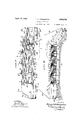
- Fig. I is a fragmentary illustration partly in sideelevation and partly in section showingV my improved ballast spreadery in association with a hopper car from which the ballast is continuously supplied.
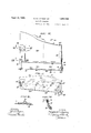
- Fig. II is a plan view'V of the spreader.
- Fig. III is a rear elevation of the spreader.
- Fig. IV shows in plan and on a larger scale than in Fig. II, the out-board side chute whereby the ballast isl released beyond the ends ofthe ties along one side of the railroad track ⁇ over the shoulder ofthe track bed.
- Fig- ⁇ V is a rear elevation of the out-board side chute shown in Fig. IV.
- Figs. VI and VII are detail sectional views taken as respectively indicated by the arrows VI--VI and VII-VII in Fig. V showing the securing means for the out-.board side chute. 75
- Fig.4 VIII is anend elevation of the side chute' drawn to a still larger scale.
- Fig. IX is a cross section of the out-board side chute taken as indicated by the arrows IX-IX in Figs. II and IV- Fig. X is a view corresponding to Fig. I showing how selfregulatory means for releasing the ballast. within the conlines of the ties are automatically actuated by the track ties incident to travel of the spreader along the railway.
- Fig. XI shows a plan view of the irl-board chute provided for distributing the ballast over the road bed in the space between trac-ks of a multietrack road.
- Fig. XII shows the rear elevation of the in-.board chute aforesaid.
- Fig. XIII is a rear elevation on an enlarged scale -of one of the self-regulatory rail tie actuated ballast release vmeans for controlling the flow of the ballast into the intervals between ties.
- Fig. XIV is a section taken as indicated by the arrows XIV-'XIV in Fig. XIII.
- Fig. XV is a section taken as indicated by the arrows XV-XV in Fig. XIV;
- Fig. XVI is a view like Fig. X showing the means for, and manner of controlling the self-regulatory release means to interrupt the flow of the ballast.
- the ballast spreader of my invention has the form of a carriage 1 comprising a hopper 2 which extends transversely7 of the rail way track, and which is supported on wheels 3 for capacity to run along the track rails 4 beneath a chute 5 of a car 6 containing the supply of ballast which is to be spread along the railway.
- Ihe draft means for the carriage 1 includes a longitudinal chain 7 which extends beneath the carriage at the center, and whereof the ends are suitably made fast to the wheel truck 8 of the car 6 as conventionally shown in Fig. I.
- the draft chain 7 is passed through a tube 9 at the bottom of the carriage l; and removable pins 10 inserted into the links of the chain immediately beyond the ends of the tube 9, serve to hold the carriage properly positioned beneath the chute 5 of the ballast supply car 6.
- the described draft arrangement obviously permits shifting of the spreader carriage from one outlet chute to another of the supply car without necessitating detachment of the chain from the car wheel trucks 8.
- the hopper 2 is substantially coeXtensive in length with the ties 11 of the railway, and fashioned from sheet metal to trough-like cross section, i. e. with sloping walls 12, 13.
- the rear wall 13 of the hopper 2 (as considered with regard to the direction of travel indicated by the arrow in Fig. I) is provided with aft discharging outlets 15, there being two such outlets for release of ballast between the rails Ll, and one to the outside of each of the rails to discharge ballast within the length of the ties.
- the flow of the ballast through the hopper discharge Outlets 15 is controlled automatically by flexible tubular bag-like devices 16 which, in effect, constitute prolongations of the outlets.
- Each of these devices 16 is, in the present instance, fashioned to tubular form by interconnecting a multiplicity of chain links 17 as shown in Figs. ⁇ XIII-XV, and attaching the upper edge links of the mesh, by welding or otherwise, to three sides of a rectangular frame 18 constructed from angle iron, the top edge links of the front face 16a of the bag being secured in a similar manner to a plate 19 which is in turn attached to the corresponding side of the frame by hinges 20. It is to be particularly noted from Figs. XIV and XV that the front face 16a and portions of the side facesl, 160 of the bag 16 are somewhat longer than the rear face 16d. As shown in Fig.
- the ballast is released only into the intervals between the ties 11 in quantities just sufhcient to fill the said intervals flush with the tie tops,-flooding of the road bed being thereby effectively prevented, while the ties are kept entirely free of ballast by the sweeping action of the bags 16.
- the ballast is uniformly distributed without waste and without requiring subsequent sweeping or raking over the width of the road bed comprehended by the ties.
- a manually actuatable means in the form of a shaft 22 which is journalled in bearings 23 secured to the wall 13 of the hopper 2 at the outside, see Figs. I, II, III, X and XV.
- the shaft 22 has actuating handles 24 of such length as to be convenient of access from the aft side of the carriage 1; and intermediate points, the said shaft is formed with crank bends 25 in line with the bags 16. Normally, the crank bends 25 occupy the positions shown in Fig. X clear of the bags 16; but when either of the handles 24 is turned to the position shown in Fig.
- the crank bends are swung under the bags 16 thereby drawing the extended bag faces 16a under the bag mouths and at the same time lifting the said bags clear of the rails 5 and ties 11 after the manner disclosed in the illustration last referred to.
- the flow of the ballast can thus be interrupted to prevent release of the ballast from the bags incident to passage of the spreader over crossings, or while the spreader is taken to and from the location of operation.
- ballast may be concurrently distributed over one shoulder of a double track road and over the space between tracks.
- I provide the spreader as shown in Figs. II and III, with appropriately congured aft discharging out-board and in-board openmouthed sheet metal chutes 26 and 27 which respectively receive the ballast from opposite ends of the hopper 2 of the carriage 1.
- out-board chute 26 slopes downward and rearward from the corresponding end of the hopper 2 whereto it is attached at the center, by a hinge-28, (Figs. II, III, IV and VI) while a hasp 29l (Figs. IV and VII)- fastened to the chute near the rear end and adapted' to engage a stud 30 on the hopper, serves to normally prevent hinge movement and to render the attachment of the said chute more firm. Further support and stability is afforded the chute 26v by vertical and horizontal chains 3l and 32, 33 which may reach from suitable anchorages on. the supply car 6.
- the out-board chute 26 is constructed with two slidingly interconnected parts 26a, 26?) whereof the latter underlaps the first as shown in Fig. IX.
- Aft flow of the ballast from the mouth of the out-board chute 26 is controlledby a Vguard plate 36, which also serves as a scraper to level the ballast discharged onto the road shoulder, and which, in order to accommodate adjustment of the chute, is made in two parts 36a, 36?; that overlap as shown in Figs. II, IV and V.
- the scraper plate sections 36a, 36?) are each provided with a horizontal series of holes 37 for selective passage of screw bolts 375e to secure the said plate sections against relative displacement after adjustment.
- guard plate 36 is disposed somewhat to the rear of the open mouth 35 of the chute 26 and supported at one end by a bracket 38 reaching rearward from the chute section 26a, while its other end is supported by a plate 39 reaching rearward from the chute section 26?).
- he bracket 38, and an inwardly turned abutment flange 41 of the end plate 39 are respectively provided with vertical lines of apertures to correspond with vertical lines of apertures 42 and 43 adjacent the side edges of the guard plate 36 for passage of removable screw bolts 44, see Figs. III, IV and V.
- the guard plate 36 permits vertical adjustment ofthe guard plate 36 to predetermin'e the depth of the ballast discharge from the chute 26.
- the section 265v of l' the chute 26 is fitted with a shoe or plow 45 which is adapted to remove any obstacles in the path of the said chute.
- the section 26.7) of the chute is furthermore provided at its outer end, with a freely revolving follower disk 46 which is appropriately journalled on the end plate 39 and operative to defiect the ballast inward of the road bed incident to release from the chute. This insures a clean, and uniformly straight limiting edge for the ⁇ ballast laid over the shoulder of the road bediby the chute 26.
- in-board chute 27 is similar in construction to the out-board chute 26 and differs from it mainly in configuration.
- the inboard chute 27 is attached to the contiguous end of the hopper 2 of the carriage by a hinge 48 which is exactly like the hinge 28iaforedescribed, see Figs. II, XI, XII.
- a hasp 49 is also here employed as a means for rendering the attachment of the in-board chute more firm.
- the vertical and horizontal chains indicated at 5l and 52, 53 in Figs. II andIII function to support and stabilize the in-board chute 27 in exact-lv the same manner as described in connection with the chains 31-33 -for the out-board chute 26.
- the bottom of the in-board chute 27 is concaved as shown in Figs. II and XII, and the associated guard and scraper plate 56 is correspondingly configured to determine the formation, for the purposes of a gutter, of a centrally de pressed layer of ballast over the area of the road bed between the ends of the ties 1l and the ties 11m of an adjacent track, seeFig. III.
- the Vguard 56 is vertically adjust-able in the same manner and for the same reasons as described in connection with the guard plate of the chute 26, through provision of vertically arranged holes 57 along its opposite side edges for passage of securing screw bolts 58. Itis to be vunderstood that the in-board chute 27 may be made with two relatively slidable parts for the purposes of extensibility in the same manner as the out-board chute 26.
- a left hand chute of the type 26 is substituted for the chute v27 herein shown, to distribute ballast over the. opposite shoulder of the road bed. This substitution may be easily effected upon loosen- "J ing the hasp 49 and withdrawing the pintle of the hinge 48 whereby the chute 26 isv connected to the hopper 2.
- a railway ballastl spreader in the form of a wheeled carriage adapted te traverse the railway track beneath a ballast supply car, and comprising a transversely-extendin ravit i ho er havino' a sloping rear wagll ivith dn afltD-Idischargirg outlet through which the ballast is released over the road bed within the coniines of the rail ties incident to progression of the spreader.
- a railway ballast spreader in the form of a carriage adapted to traverse the railway track, comprising a transversely extending gravity hopper having a sloping rear wall with aft-discharging outlets through which the ballast is released over the road bed within the contines of the rail ties, incident to progression of the spreader.
- a railway ballast spreader in the form of a carriage adapted to traverse the railway track, comprising a transversely extending gravity hopper; and flexible tubular means to automatically govern the flow through discharge outlets of the hopper so that the ballast is released only into the intervals between rail ties incident to progression of the spreader.
- a railway ballast spreader in the form of a carriage adapted to traverse the railway track, comprising a transversely extending gravity hopper; and flexible tubular means actuated through contact with the rail ties incident to progression of the spreader, to govern flow through discharge outlets of the hopper so that the ballast is released only into the intervals between the rail ties.
- a railway ballast spreader in the form of a carriage adapted to traverse the railway track, comprising a transversely extending gravity hopper with aft-discharging outlets for the ballast; and open-ended ilexible bags forming continuations of the hopper discharge outlets and adapted to be closed through contact with the rail ties incident to progression of the spreader so that the ballast is released only into the intervals between the ties.
- a railway ballast spreader in the form of a carriage adapted to tra-verse the railway track, comprising a transversely extending gravity hopper with aft-discharging outlets; and open ended flexible bags of interconnected chain links constituting continuations of the hopper outlets and adapted to be closed through contact with the rail ties incident to progression of the spreader so that the ballast is released only into the intervals between the ties.
- a railway ballast spreader in the form of a carriage adapted to traverse the railway track, comprising a transversely-extending gravity hopper with aft-discharging outlets through which ballast 'is released over the road bed within the confines of the railroad ties incident to progression of the spreader;
- a railway ballast spreader in the form of a carriage adapted to traverse the railway track, comprising a t-ransversely extending gravity hopper with aft-discharging outlets through which ballast is released over the road bed within the confines of the rail ties incident to progression of the spreader; and aft-discharging iianking chutes receiving ballast from opposite ends of the hopper for concurrent release over the road bed beyond the ends of the ties, the said chutes being extensible for the purpose of varying the width of the ballast spread released by them.
- a railway ballast spreader in the form of a carriage adapted to traverse the railway track, comprising a transversely extending gravity hopper with aft-discharging outlets through which ballast is released over the road bed within the contines of the rail ties incident to progression of the spreader; and aft-discharging flanking chutes receiving ballast from opposite ends of the hopper for concurrent release over the road bed beyond the ends of the ties; and adjustable means at the discharge ends of the chutes whereby the depth of the ballast released from the said chutes may be varied.
- a railway ballast spreader iii the form of a carriage adapted to traverse the railway track, comprising a transversely extending gravity hopper with aft-discharging outlets through which ballast is released over the road bed within the contines of the rail ties incident to progression of the spreader; aftdischarging flanking chutes receiving ballast from opposite ends ot the hopper for concurrent release over the road bed beyond the ends of the ties, and vertically adjustable guards whereby the depth of the ballast released through the outlets of the chutes may be varied.
- a railway ballast spreader in the form of a carriage adapted to traverse the railway track, comprising transversely extending aftarging gravity hopper for releasing ⁇ disch I ballast within the conlines ot the track ties; aft-discharging downwardly inclined flanking chutes adapted to receive ballast from the opposite ends of the hopper for release beyond the ends of the ties over the shoulders of the road bed; and freely rotating disks at the outer ends of the chutes for deflecting the ballast inwards thereby to determine sharply defined border lines for the track shoulders.
- a railway ballast spreader iii the form of a carriage adapted to traverse a railway track, comprising a transversely extending aft-discharging gravity hopper for releasing ballast within the contines of the track ties; flanking chutes receiving ballast from opposite ends ot the hopper for concurrent release beyond the ends of the ties means for controlling the flow of the ballast from the hopper into the said chutes; and separate means at the discharge ends of the chutes to govern the rate of ballast released from the said chutes.
- a railway ballast spreader in the form of a wheeled hopper carriage adapted to traverse the railway track under a ballast supply car and to release ballast over the road bed; and draft means for the carriage including a chain extending longitudinally beneath the supply car and through a tube centrally of the carriage hopper, and removable pins to engage the links of the chain immediately beyond the ends of the tube aforesaid permitting positional adjustment of the carriage along the length of the supply car.
- a railway ballast spreader in the form of a carriage adapted to traverse the railway track, comprising a transversely extending gravity hopper with aft discharging outlets; means actuated through contact with the rail ties incident to progression of the spreader, to govern flow through the discharge outlets of the hopper so that the ballast is released only into the intervals between the rail ties; and means whereby the ballast release governing means may be lifted clear of the ties above the level of the track rails with attend ant interruption in the iow of the ballast.
- a railway ballast spreader in the form of a carriage adapted to traverse the railway track, comprising a transversely extending hopper with aft discharging outlets for the ballast 5 and open-ended flexible bags forming continuations of the hopper discharge outlets and adapted to be closed through contact with the rail ties incident to 4progression of the spreader so that ballast is released only into the intervals between the ties, and means whereby the bags may be lifted from beneath clear of the ties to a level above the rails with attendant closure of the bags to interrupt flow through them.
- a railway ballast spreader in the form of a carriage adapted to traverse a railway track, comprising a transverselycxtending gravity hopper with outlets through which the ballast is released over the road bed within the confines of the rail ties incident to progression of the spreader; and aft-discharging flanking chutes receiving ballast from the opposite ends of the hopper for concurrent release beyond the ends of the ties over the shoulders of the road bed, the said chutes being formed with extensible parts for the purpose of lateral adjustment to predetermine the width of ballast spread over the road shoulders.
- a railway ballast spreader in the form of a carriage adapted to traverse the railway track, comprising a transversely extending gravity hopper with outlets through which ballast is released over the road bed within the confines of the rail ties incident to progression of the spreader; aft-discharging open-mouthed flanking chutes receiving ballast from the opposite ends of the hopper for concurrent release from the road bed beyond the ends of the ties; and vertically-adjustable scraper plates rearward of the open mouths of the chutes to control release of the ballast and to level the ballast over the road shoulders.
- a railway ballast spreader in the form of a carriage adapted to traverse the railway track, comprising a transversely extending gravity hopper with outlets through which ballast is released over the road bed within the confines of the rail ties incident to progression of the spreader; aft-discharging open-mouthed flanking chutes receiving ballast from the opposite ends of the hopper for concurrent release from the road bed beyond the ends .of the ties; and vertically-adjustable scraper plates rearward of the open mouth of the chutes to control release of the ballast and to level the ballast spread over road shoulders, the said chutes and the scraper plates being extensible for adaptation of the spreader to track shoulders of different widths.
Landscapes
- Engineering & Computer Science (AREA)
- Architecture (AREA)
- Civil Engineering (AREA)
- Structural Engineering (AREA)
- Machines For Laying And Maintaining Railways (AREA)
Description
April 19, 1932- E. MA LIVINGSTON BALLAS T SPREADER Filed March 18 6 Sheets-Sheet l April 19`, 1932. E. MA LIVINGSTON BALLASTv SPREADER Filed March 18,1951 6 sheets-sheet 2 mmwmmNNNmhNNm @NEN WITNJLE v INVENTOR ATTORNEYS.
Apnl '19,I 1932,
E. M, LIVINGSTON 1,854,799
BALLAST SPREADER Fled'March 18, 1951 G Sheets-Sheet 3 WI TNESSES INVENTOR; EmmdMLz/zzgsoiz,
A TTORNE YS.
April 19, 1932 E. M. LivlNGsToN 1,854,799
BALLAST SPREADER INVENTQR: Ulm/1262.44w Zinrgs/Oa,
. ATTORNEYS.
APIKY 19, 1932' E.l M. LIVINGSTON 1,854,799
BAIJLAST SPREADER Filed March 18, 1951 6 Shams-Sheet 5 FIC?. .Z
WITNESSES INVENTOR- Apri! -g, 1932. E, M. L|V1NG$TQN 1,854,799
BALLAST S PREADER Filed March 18, 1951 6 Sheets-Shawl 6 alllii A *A Ilnni Ehi anni al i nwwz-? @www Marg-fv T- 1 1:11p; :L il@ TIGLI? ORNEYS.
Patented Apr. 19, 1932 EDI/[UND M. LIVINGSTON, OF CHAMBERSBURG', PENNSYLVANIA BALLAST SPREADER Application led March 18, 1931. Serial N o. 523,508.`
possible the uniform spreading of ballast along railways in the area of the road bed between rails, as well as over the shoulders toV opposite sides of single track roads and over the space between adjacent tracks of multi track roads7 without flooding ofthe ties or requiring subsequent raking to distribute the ballast. l
In connection with a spreader suitable to the attainment of the indicated desiderata,
` it is an obj ect of my invention to provide selfregulatory means functional,y incident to pro` gression of the apparatus over the railway, to govern gravitational flow of the ballast so that the latter is released only into the intervals between ties and in such quantities as to predetermine a flush fill in the said intervals.
Another object of my invention is to provide control means whereby the self-regula-- tory release Vmeans aforesaid may be rendered inoperative to prevent deposit of' ballast when crossings are being over-travelled or when the spreader is being taken to or from the location of operation.
A further object of my invention is to pro# vide, in connection with a main hopper from which ballast is distributed between track rails and iii-board and out-board chutes forV concurrently releasing ballast beyond the 'l ends of the rail ties, means whereby the said chutes may be lifted above the level of the rails when their use is not required as well as for the reasons stated Vabove with regard .to the control of the self-regulatory release means.
Still another object of my invention is to provide means capable of cooperating with the out-board chute aforesaid m accurately limiting the lateral distribution of the bali last, thereby to define sharp ant. straight terminal lines for the shoulders of the road bed.
My invention is also in part directed toward the provision of means whereby the distribution of the ballast may be confined within the limits of the ties when coverage ofV the shoulder of the track bed is not required '.or desired.
Further objects andatten-dant advantages of my invention will be manifest from the detailed description follow-ing in coordination with the attached drawings, wherein Fig. I is a fragmentary illustration partly in sideelevation and partly in section showingV my improved ballast spreadery in association with a hopper car from which the ballast is continuously supplied.
Fig. II is a plan view'V of the spreader.
Fig. III is a rear elevation of the spreader.
Fig. IV shows in plan and on a larger scale than in Fig. II, the out-board side chute whereby the ballast isl released beyond the ends ofthe ties along one side of the railroad track `over the shoulder ofthe track bed.
Fig-` V is a rear elevation of the out-board side chute shown in Fig. IV.
Figs. VI and VII are detail sectional views taken as respectively indicated by the arrows VI--VI and VII-VII in Fig. V showing the securing means for the out-.board side chute. 75
Fig.4 VIII is anend elevation of the side chute' drawn to a still larger scale.
Fig. IX is a cross section of the out-board side chute taken as indicated by the arrows IX-IX in Figs. II and IV- Fig. X is a view corresponding to Fig. I showing how selfregulatory means for releasing the ballast. within the conlines of the ties are automatically actuated by the track ties incident to travel of the spreader along the railway.
Fig. XI shows a plan view of the irl-board chute provided for distributing the ballast over the road bed in the space between trac-ks of a multietrack road.
Fig. XII shows the rear elevation of the in-.board chute aforesaid.
Fig. XIII is a rear elevation on an enlarged scale -of one of the self-regulatory rail tie actuated ballast release vmeans for controlling the flow of the ballast into the intervals between ties.
Fig. XIV is a section taken as indicated by the arrows XIV-'XIV in Fig. XIII.
Fig. XV is a section taken as indicated by the arrows XV-XV in Fig. XIV; and
Fig. XVI is a view like Fig. X showing the means for, and manner of controlling the self-regulatory release means to interrupt the flow of the ballast.
The ballast spreader of my invention has the form of a carriage 1 comprising a hopper 2 which extends transversely7 of the rail way track, and which is supported on wheels 3 for capacity to run along the track rails 4 beneath a chute 5 of a car 6 containing the supply of ballast which is to be spread along the railway.
Ihe draft means for the carriage 1 includes a longitudinal chain 7 which extends beneath the carriage at the center, and whereof the ends are suitably made fast to the wheel truck 8 of the car 6 as conventionally shown in Fig. I. The draft chain 7 is passed through a tube 9 at the bottom of the carriage l; and removable pins 10 inserted into the links of the chain immediately beyond the ends of the tube 9, serve to hold the carriage properly positioned beneath the chute 5 of the ballast supply car 6. The described draft arrangement obviously permits shifting of the spreader carriage from one outlet chute to another of the supply car without necessitating detachment of the chain from the car wheel trucks 8.
The hopper 2, it will be noted from Figs. II and III, is substantially coeXtensive in length with the ties 11 of the railway, and fashioned from sheet metal to trough-like cross section, i. e. with sloping walls 12, 13. The rear wall 13 of the hopper 2 (as considered with regard to the direction of travel indicated by the arrow in Fig. I) is provided with aft discharging outlets 15, there being two such outlets for release of ballast between the rails Ll, and one to the outside of each of the rails to discharge ballast within the length of the ties. The flow of the ballast through the hopper discharge Outlets 15 is controlled automatically by flexible tubular bag-like devices 16 which, in effect, constitute prolongations of the outlets. Y Each of these devices 16 is, in the present instance, fashioned to tubular form by interconnecting a multiplicity of chain links 17 as shown in Figs. `XIII-XV, and attaching the upper edge links of the mesh, by welding or otherwise, to three sides of a rectangular frame 18 constructed from angle iron, the top edge links of the front face 16a of the bag being secured in a similar manner to a plate 19 which is in turn attached to the corresponding side of the frame by hinges 20. It is to be particularly noted from Figs. XIV and XV that the front face 16a and portions of the side facesl, 160 of the bag 16 are somewhat longer than the rear face 16d. As shown in Fig. III, there are guide pieces 21 secured to the rear of the hopper 2 along 0pposite edges of the ballast discharge openings 15. These guide pieces 21 slidingly receive the side edges of the frames 18 of the bags 16 and thus serve to removably hold the said bags in place on the carriage 1. By virtue of the described arrangement, it is evident that the gravitational discharge of ballast from the hopper 2 through the outlets 15 and the bags 16 will be aft or rear ward of the direction of travel of the carriage 1. In passing over the intervals between the ties 11, the bags open as shown in Fig. I, thereby allowing free flow of the ballast through them; but in encountering the ties, the long frontal faces 16a of the said bags are caused to underlap the bag mouths as shown in Fig. X, and accordingly interrupt the ballast flow temporarily. As a consequence, the ballast is released only into the intervals between the ties 11 in quantities just sufhcient to fill the said intervals flush with the tie tops,-flooding of the road bed being thereby effectively prevented, while the ties are kept entirely free of ballast by the sweeping action of the bags 16. Thus with my improved spreader, the ballast is uniformly distributed without waste and without requiring subsequent sweeping or raking over the width of the road bed comprehended by the ties.
For the purpose of simultaneously control ling the ballast releasing bags 16, I have provided a manually actuatable means in the form of a shaft 22 which is journalled in bearings 23 secured to the wall 13 of the hopper 2 at the outside, see Figs. I, II, III, X and XV. At opposite ends, the shaft 22 has actuating handles 24 of such length as to be convenient of access from the aft side of the carriage 1; and intermediate points, the said shaft is formed with crank bends 25 in line with the bags 16. Normally, the crank bends 25 occupy the positions shown in Fig. X clear of the bags 16; but when either of the handles 24 is turned to the position shown in Fig. XVI, the crank bends are swung under the bags 16 thereby drawing the extended bag faces 16a under the bag mouths and at the same time lifting the said bags clear of the rails 5 and ties 11 after the manner disclosed in the illustration last referred to. The flow of the ballast can thus be interrupted to prevent release of the ballast from the bags incident to passage of the spreader over crossings, or while the spreader is taken to and from the location of operation.
In order that ballast may be concurrently distributed over one shoulder of a double track road and over the space between tracks, I provide the spreader as shown in Figs. II and III, with appropriately congured aft discharging out-board and in-board openmouthed sheet metal chutes 26 and 27 which respectively receive the ballast from opposite ends of the hopper 2 of the carriage 1. The
cri
out-board chute 26 slopes downward and rearward from the corresponding end of the hopper 2 whereto it is attached at the center, by a hinge-28, (Figs. II, III, IV and VI) while a hasp 29l (Figs. IV and VII)- fastened to the chute near the rear end and adapted' to engage a stud 30 on the hopper, serves to normally prevent hinge movement and to render the attachment of the said chute more firm. Further support and stability is afforded the chute 26v by vertical and horizontal chains 3l and 32, 33 which may reach from suitable anchorages on. the supply car 6. For the purposes of sidewise extensibility, the out-board chute 26 is constructed with two slidingly interconnected parts 26a, 26?) whereof the latter underlaps the first as shown in Fig. IX. Aft flow of the ballast from the mouth of the out-board chute 26 is controlledby a Vguard plate 36, which also serves as a scraper to level the ballast discharged onto the road shoulder, and which, in order to accommodate adjustment of the chute, is made in two parts 36a, 36?; that overlap as shown in Figs. II, IV and V. Along the region of overlap, the scraper plate sections 36a, 36?) are each provided with a horizontal series of holes 37 for selective passage of screw bolts 375e to secure the said plate sections against relative displacement after adjustment. From Figs. II, IV, VIII and IX it will be observed that the guard plate 36 is disposed somewhat to the rear of the open mouth 35 of the chute 26 and supported at one end by a bracket 38 reaching rearward from the chute section 26a, while its other end is supported by a plate 39 reaching rearward from the chute section 26?).
he bracket 38, and an inwardly turned abutment flange 41 of the end plate 39 are respectively provided with vertical lines of apertures to correspond with vertical lines of apertures 42 and 43 adjacent the side edges of the guard plate 36 for passage of removable screw bolts 44, see Figs. III, IV and V.
This arrangement permits vertical adjustment ofthe guard plate 36 to predetermin'e the depth of the ballast discharge from the chute 26. At its outer end,.the section 265v of l' the chute 26 is fitted with a shoe or plow 45 which is adapted to remove any obstacles in the path of the said chute. The section 26.7) of the chute is furthermore provided at its outer end, with a freely revolving follower disk 46 which is appropriately journalled on the end plate 39 and operative to defiect the ballast inward of the road bed incident to release from the chute. This insures a clean, and uniformly straight limiting edge for the `ballast laid over the shoulder of the road bediby the chute 26.
'Ihe in-board chute 27 is similar in construction to the out-board chute 26 and differs from it mainly in configuration.` The inboard chute 27 is attached to the contiguous end of the hopper 2 of the carriage by a hinge 48 which is exactly like the hinge 28iaforedescribed, see Figs. II, XI, XII. A hasp 49 is also here employed as a means for rendering the attachment of the in-board chute more firm. The vertical and horizontal chains indicated at 5l and 52, 53 in Figs. II andIII function to support and stabilize the in-board chute 27 in exact-lv the same manner as described in connection with the chains 31-33 -for the out-board chute 26. The bottom of the in-board chute 27 is concaved as shown in Figs. II and XII, and the associated guard and scraper plate 56 is correspondingly configured to determine the formation, for the purposes of a gutter, of a centrally de pressed layer of ballast over the area of the road bed between the ends of the ties 1l and the ties 11m of an adjacent track, seeFig. III. The Vguard 56 is vertically adjust-able in the same manner and for the same reasons as described in connection with the guard plate of the chute 26, through provision of vertically arranged holes 57 along its opposite side edges for passage of securing screw bolts 58. Itis to be vunderstood that the in-board chute 27 may be made with two relatively slidable parts for the purposes of extensibility in the same manner as the out-board chute 26.
For operation of the spreader on single track railways, a left hand chute of the type 26 is substituted for the chute v27 herein shown, to distribute ballast over the. opposite shoulder of the road bed. This substitution may be easily effected upon loosen- "J ing the hasp 49 and withdrawing the pintle of the hinge 48 whereby the chute 26 isv connected to the hopper 2.
Obviously through attaching the chutes 26 and 27 with hinges as described, it is possible i In order to interrupt the flow of the ballast from the hopper 2 into the chutes 26 and 27 when ballast is to bedistributed only over that portion of the roadbed within the confines of the ties Il, I have fitted the hopper 2 at opposite ends with gates 60. These gates 60 may be of stout sheet metal, and as shown, hinged at one end to brackets 61 riveted or otherwise secured to the frontal wall l2 of the hopper 2. Adjacent their opposite ends the'gates 60 are provided with eyes 62 for attachment of chains 63, which, as suggested in Fig. I, may be engaged with a projecting portion of the supply car 6 so as to normally hold the gates in raised position.
Having thus described my invention, lI claim: Y
l. A railway ballastl spreader in the form of a wheeled carriage adapted te traverse the railway track beneath a ballast supply car, and comprising a transversely-extendin ravit i ho er havino' a sloping rear wagll ivith dn afltD-Idischargirg outlet through which the ballast is released over the road bed within the coniines of the rail ties incident to progression of the spreader.
2. A railway ballast spreader in the form of a carriage adapted to traverse the railway track, comprising a transversely extending gravity hopper having a sloping rear wall with aft-discharging outlets through which the ballast is released over the road bed within the contines of the rail ties, incident to progression of the spreader.
3. A railway ballast spreader in the form of a carriage adapted to traverse the railway track, comprising a transversely extending gravity hopper; and flexible tubular means to automatically govern the flow through discharge outlets of the hopper so that the ballast is released only into the intervals between rail ties incident to progression of the spreader.
4. A railway ballast spreader in the form of a carriage adapted to traverse the railway track, comprising a transversely extending gravity hopper; and flexible tubular means actuated through contact with the rail ties incident to progression of the spreader, to govern flow through discharge outlets of the hopper so that the ballast is released only into the intervals between the rail ties.
5. A railway ballast spreader in the form of a carriage adapted to traverse the railway track, comprising a transversely extending gravity hopper with aft-discharging outlets for the ballast; and open-ended ilexible bags forming continuations of the hopper discharge outlets and adapted to be closed through contact with the rail ties incident to progression of the spreader so that the ballast is released only into the intervals between the ties.
6. A railway ballast spreader in the form of a carriage adapted to tra-verse the railway track, comprising a transversely extending gravity hopper with aft-discharging outlets; and open ended flexible bags of interconnected chain links constituting continuations of the hopper outlets and adapted to be closed through contact with the rail ties incident to progression of the spreader so that the ballast is released only into the intervals between the ties.
7. A railway ballast spreader in the form of a carriage adapted to traverse the railway track, comprising a transversely-extending gravity hopper with aft-discharging outlets through which ballast 'is released over the road bed within the confines of the railroad ties incident to progression of the spreader;
and downwardly and rearwardly-sloping aft-discharging anking chutes receiving ballast from opposite ends of the hopper for 4 concurrent release over the road bed beyond the ends of the ties.
att discharging 8. A railway ballast spreader in the form of a carriage adapted to traverse the railway track, comprising a t-ransversely extending gravity hopper with aft-discharging outlets through which ballast is released over the road bed within the confines of the rail ties incident to progression of the spreader; and aft-discharging iianking chutes receiving ballast from opposite ends of the hopper for concurrent release over the road bed beyond the ends of the ties, the said chutes being extensible for the purpose of varying the width of the ballast spread released by them.
9. A railway ballast spreader in the form of a carriage adapted to traverse the railway track, comprising a transversely extending gravity hopper with aft-discharging outlets through which ballast is released over the road bed within the contines of the rail ties incident to progression of the spreader; and aft-discharging flanking chutes receiving ballast from opposite ends of the hopper for concurrent release over the road bed beyond the ends of the ties; and adjustable means at the discharge ends of the chutes whereby the depth of the ballast released from the said chutes may be varied.
l0. A railway ballast spreader iii the form of a carriage adapted to traverse the railway track, comprising a transversely extending gravity hopper with aft-discharging outlets through which ballast is released over the road bed within the contines of the rail ties incident to progression of the spreader; aftdischarging flanking chutes receiving ballast from opposite ends ot the hopper for concurrent release over the road bed beyond the ends of the ties, and vertically adjustable guards whereby the depth of the ballast released through the outlets of the chutes may be varied.
l1. A railway ballast spreader in the form of a carriage adapted to traverse the railway track, comprising transversely extending aftarging gravity hopper for releasing` disch I ballast within the conlines ot the track ties; aft-discharging downwardly inclined flanking chutes adapted to receive ballast from the opposite ends of the hopper for release beyond the ends of the ties over the shoulders of the road bed; and freely rotating disks at the outer ends of the chutes for deflecting the ballast inwards thereby to determine sharply defined border lines for the track shoulders.
l2. A railway ballast spreader iii the form of a carriage adapted to traverse a railway track, comprising a transversely extending aft-discharging gravity hopper for releasing ballast within the contines of the track ties; flanking chutes receiving ballast from opposite ends ot the hopper for concurrent release beyond the ends of the ties means for controlling the flow of the ballast from the hopper into the said chutes; and separate means at the discharge ends of the chutes to govern the rate of ballast released from the said chutes.
13. A railway ballast spreader in the form of a wheeled hopper carriage adapted to traverse the railway track under a ballast supply car and to release ballast over the road bed; and draft means for the carriage including a chain extending longitudinally beneath the supply car and through a tube centrally of the carriage hopper, and removable pins to engage the links of the chain immediately beyond the ends of the tube aforesaid permitting positional adjustment of the carriage along the length of the supply car.
14. A railway ballast spreader in the form of a carriage adapted to traverse the railway track, comprising a transversely extending gravity hopper with aft discharging outlets; means actuated through contact with the rail ties incident to progression of the spreader, to govern flow through the discharge outlets of the hopper so that the ballast is released only into the intervals between the rail ties; and means whereby the ballast release governing means may be lifted clear of the ties above the level of the track rails with attend ant interruption in the iow of the ballast.
15. A railway ballast spreader in the form of a carriage adapted to traverse the railway track, comprising a transversely extending hopper with aft discharging outlets for the ballast 5 and open-ended flexible bags forming continuations of the hopper discharge outlets and adapted to be closed through contact with the rail ties incident to 4progression of the spreader so that ballast is released only into the intervals between the ties, and means whereby the bags may be lifted from beneath clear of the ties to a level above the rails with attendant closure of the bags to interrupt flow through them.
16. A railway ballast spreader in the form of a carriage adapted to traverse a railway track, comprising a transverselycxtending gravity hopper with outlets through which the ballast is released over the road bed within the confines of the rail ties incident to progression of the spreader; and aft-discharging flanking chutes receiving ballast from the opposite ends of the hopper for concurrent release beyond the ends of the ties over the shoulders of the road bed, the said chutes being formed with extensible parts for the purpose of lateral adjustment to predetermine the width of ballast spread over the road shoulders.
17. A railway ballast spreader in the form of a carriage adapted to traverse the railway track, comprising a transversely extending gravity hopper with outlets through which ballast is released over the road bed within the confines of the rail ties incident to progression of the spreader; aft-discharging open-mouthed flanking chutes receiving ballast from the opposite ends of the hopper for concurrent release from the road bed beyond the ends of the ties; and vertically-adjustable scraper plates rearward of the open mouths of the chutes to control release of the ballast and to level the ballast over the road shoulders.
18. A railway ballast spreader in the form of a carriage adapted to traverse the railway track, comprising a transversely extending gravity hopper with outlets through which ballast is released over the road bed within the confines of the rail ties incident to progression of the spreader; aft-discharging open-mouthed flanking chutes receiving ballast from the opposite ends of the hopper for concurrent release from the road bed beyond the ends .of the ties; and vertically-adjustable scraper plates rearward of the open mouth of the chutes to control release of the ballast and to level the ballast spread over road shoulders, the said chutes and the scraper plates being extensible for adaptation of the spreader to track shoulders of different widths. y
In testimony whereof, I have hereunto signed my name at Philadelphia, Pennsylvania, this 16th day of March, 1931.
EDMUND M. LIVINGSTON.
Priority Applications (1)
| Application Number | Priority Date | Filing Date | Title |
|---|---|---|---|
| US523508A US1854799A (en) | 1931-03-18 | 1931-03-18 | Ballast spreader |
Applications Claiming Priority (1)
| Application Number | Priority Date | Filing Date | Title |
|---|---|---|---|
| US523508A US1854799A (en) | 1931-03-18 | 1931-03-18 | Ballast spreader |
Publications (1)
| Publication Number | Publication Date |
|---|---|
| US1854799A true US1854799A (en) | 1932-04-19 |
Family
ID=24085324
Family Applications (1)
| Application Number | Title | Priority Date | Filing Date |
|---|---|---|---|
| US523508A Expired - Lifetime US1854799A (en) | 1931-03-18 | 1931-03-18 | Ballast spreader |
Country Status (1)
| Country | Link |
|---|---|
| US (1) | US1854799A (en) |
Cited By (1)
| Publication number | Priority date | Publication date | Assignee | Title |
|---|---|---|---|---|
| US3667400A (en) * | 1970-11-03 | 1972-06-06 | Sergio Rene Damy | Railway ballast distributing car door assembly |
-
1931
- 1931-03-18 US US523508A patent/US1854799A/en not_active Expired - Lifetime
Cited By (1)
| Publication number | Priority date | Publication date | Assignee | Title |
|---|---|---|---|---|
| US3667400A (en) * | 1970-11-03 | 1972-06-06 | Sergio Rene Damy | Railway ballast distributing car door assembly |
Similar Documents
| Publication | Publication Date | Title |
|---|---|---|
| EP0426004B1 (en) | Machine for collecting and redistributing ballast | |
| AT404039B (en) | MACHINE FOR DISTRIBUTING AND PLANNING THE BED | |
| DE4312585C2 (en) | System for the continuous renovation of ballast bedding of a track | |
| EP0771909B1 (en) | Machine for dismantling old and installing new railway tracks | |
| EP0436757B1 (en) | Railway track tamping machine | |
| JPS6046202B2 (en) | Self-propelled track construction machine | |
| CH693454A5 (en) | A bulk material. | |
| DE4108743C2 (en) | Track-moving machine for distributing and leveling ballast ballast | |
| DE4108742C2 (en) | Track-moving machine for distributing and profiling the ballast ballast | |
| US1854799A (en) | Ballast spreader | |
| US5201127A (en) | Self metering ballast system | |
| SK278174B6 (en) | Track machine for dividing and profiling of gravel bed of track | |
| EP1106734B1 (en) | Apparatus for laying railway tracks | |
| SK271592A3 (en) | Machine device for interception, storage and dividing of track gravel | |
| US3371826A (en) | Ballast delivering mechanism | |
| US2284035A (en) | Ballast cleaning apparatus | |
| US1743579A (en) | Means for discharging ballast | |
| WO2013131026A1 (en) | System and method for mobile subvehicular access and treatment of ground surfaces about occupied rail tracks | |
| US4235029A (en) | Machine for cleaning railway tracks | |
| SK278042B6 (en) | Device for pouring of gravel and tamping of track | |
| US2116504A (en) | Material distributor and spreader | |
| DE2714050C2 (en) | ||
| US2555173A (en) | Ballast spreader | |
| US1732545A (en) | Means for distributing ballast | |
| SU728724A3 (en) | Rubble cleaning machine |