US1854774A - Method of introducing highly volatile liquids into an engine cylinder - Google Patents
Method of introducing highly volatile liquids into an engine cylinder Download PDFInfo
- Publication number
- US1854774A US1854774A US521216A US52121631A US1854774A US 1854774 A US1854774 A US 1854774A US 521216 A US521216 A US 521216A US 52121631 A US52121631 A US 52121631A US 1854774 A US1854774 A US 1854774A
- Authority
- US
- United States
- Prior art keywords
- highly volatile
- engine cylinder
- volatile liquids
- ether
- introducing highly
- Prior art date
- Legal status (The legal status is an assumption and is not a legal conclusion. Google has not performed a legal analysis and makes no representation as to the accuracy of the status listed.)
- Expired - Lifetime
Links
- 238000000034 method Methods 0.000 title description 9
- 239000007788 liquid Substances 0.000 title description 4
- RTZKZFJDLAIYFH-UHFFFAOYSA-N Diethyl ether Chemical compound CCOCC RTZKZFJDLAIYFH-UHFFFAOYSA-N 0.000 description 24
- 238000002485 combustion reaction Methods 0.000 description 9
- 239000000446 fuel Substances 0.000 description 5
- 239000002360 explosive Substances 0.000 description 4
- 239000000203 mixture Substances 0.000 description 4
- 239000003921 oil Substances 0.000 description 4
- 230000001627 detrimental effect Effects 0.000 description 2
- 239000010687 lubricating oil Substances 0.000 description 2
- 239000003039 volatile agent Substances 0.000 description 2
- 230000000694 effects Effects 0.000 description 1
- 238000009950 felting Methods 0.000 description 1
- 238000001914 filtration Methods 0.000 description 1
- 238000010304 firing Methods 0.000 description 1
- 239000003517 fume Substances 0.000 description 1
- 239000007789 gas Substances 0.000 description 1
- 239000011521 glass Substances 0.000 description 1
- 230000001939 inductive effect Effects 0.000 description 1
- 229920006395 saturated elastomer Polymers 0.000 description 1
Images
Classifications
-
- F—MECHANICAL ENGINEERING; LIGHTING; HEATING; WEAPONS; BLASTING
- F02—COMBUSTION ENGINES; HOT-GAS OR COMBUSTION-PRODUCT ENGINE PLANTS
- F02N—STARTING OF COMBUSTION ENGINES; STARTING AIDS FOR SUCH ENGINES, NOT OTHERWISE PROVIDED FOR
- F02N99/00—Subject matter not provided for in the other groups of this subclass
- F02N99/002—Starting combustion engines by ignition means
- F02N99/008—Providing a combustible mixture outside the cylinder
Definitions
- Our present invention relates to the art of internal combustion engines and more particularly to a method of introducing highly volatile liquids into an engine cylinder.
- the purpose of our invention is to PI'OVIClG a method of introducing ether, or like volatiles, into the combustion chamber of a gasoline motor.
- a further object is to provide means for 1ntroducing ether into a combustion chamber which provides a more or less uniform flow, at the same time almost entirely eliminating any hazard.
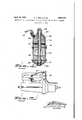
- Figure 1 is a vertical sectional view showing a device which may be satisfactorily used M in rrying out our method.
- Figure 2 is an elevation showing the device of Figure 1 and its general relationship to a gasoline motor.
- numeral 10 designates the vapor bowl which may be provided with a bracket suitable for bolting the'same in place, as shown at 12. Disposed near the lower portion of dome 10 are a series of filter screens 14,.whose purpose is to finally divide the oil vapor. As a matter of convenience so as to be able to tell definitely whether the device contains oil or' not, we provide a transparent glass 16, which in turn is supported with the base member 18.
- a central tube member 20 is provided to hold the aforementioned members together in operative'relationship and also to provide means for conducting air through the intake openings 22 down its central passageway 24 and out the discharge openings 26.
- Dome member 10 is provided at some convenient point with a discharge fitting 28 to which is suitably attached a section line 30 which is attached to the intake manifold of the motor the device is to serve.
Landscapes
- Engineering & Computer Science (AREA)
- Chemical & Material Sciences (AREA)
- Combustion & Propulsion (AREA)
- Mechanical Engineering (AREA)
- General Engineering & Computer Science (AREA)
- Cylinder Crankcases Of Internal Combustion Engines (AREA)
Description
April 19, 1932. c. J. WELLS ET AL 1,854,774
METHOD OF INTRODUCING HIGHLY VOLATILE LIQUIDS INTO AN ENGINE YLINDER- Filed March 9,' 1931 INVENTOR EYRU-El nT WELL-E:
HAROLD T/V. FENLIN G- ATTORNEYS Patented Apr. 19 1932 PATENT OFFICE CYRUS J. WELLSAND HAROLD W. FEMLING', OF SEATTLE, WASHINGTON METHOD OF INTRODUCING HIGHLY VOLATILE LIQUIDS INTO AN ENGINE CYLINDER,
Application filed March 9,
Our present invention relates to the art of internal combustion engines and more particularly to a method of introducing highly volatile liquids into an engine cylinder.
Internal combustion engines of the type ordinarily designated as gas engines operate by inducing into their combustion chamber in rapid succession an explosive mixture of alr and liquld fuel. However, in recent '10 years in the interest of general conservation ether may be taken as an example.
Many persons have used ether by mixing the same with the gasoline in the large gasoline tank provided. This has proven to be not only unsatisfactory but very dangerous.
WVhen a small amount of ether is put in a comparatively large gasoline tank which tank is vented out of necessity, it soon goes out of solution and is vaporized and lost. Further, when there is considerable space in the gasoline tank the volatilized ether and the fumes of the gasoline produce an ex tremely sensitive explosive mixture and many serious accidents have resulted from this use of ether. Therefore, I V
The purpose of our invention is to PI'OVIClG a method of introducing ether, or like volatiles, into the combustion chamber of a gasoline motor.
A further object is to provide means for 1ntroducing ether into a combustion chamber which provides a more or less uniform flow, at the same time almost entirely eliminating any hazard.
Other and more specific objects will be apparent from the following description taken in connection with the accompanying drawings, wherein Figure 1 is a vertical sectional view showing a device which may be satisfactorily used M in rrying out our method.
1931. Serial No. 521,216.
Figure 2 is an elevation showing the device of Figure 1 and its general relationship to a gasoline motor.
. Referring to the drawings throughout which like reference characters indicate like parts, numeral 10 designates the vapor bowl which may be provided with a bracket suitable for bolting the'same in place, as shown at 12. Disposed near the lower portion of dome 10 are a series of filter screens 14,.whose purpose is to finally divide the oil vapor. As a matter of convenience so as to be able to tell definitely whether the device contains oil or' not, we provide a transparent glass 16, which in turn is supported with the base member 18. A central tube member 20 is provided to hold the aforementioned members together in operative'relationship and also to provide means for conducting air through the intake openings 22 down its central passageway 24 and out the discharge openings 26. Dome member 10 is provided at some convenient point with a discharge fitting 28 to which is suitably attached a section line 30 which is attached to the intake manifold of the motor the device is to serve.
Method of operation It has been found that when ether or like high volatiles are introduced into the combustion chamber of a motor, extremely high temperature is maintained and to counteract this condition it has been found necessary to include with the ether introduced an amount of high flash lubricating oil which will make up for that destroyed by the additional heat. To accomplish our general results, therefore, it has been found necessary to use that class of device ordinarily referred to as an internal combustion chamber lubricator. There are many such devices well developed and on the market, most of which can be used for our purpose. .However, it has been found that the so-called vaporized type is the most satisfactory. A typical example of the same is shown in section in Figure 1.
'the particular motor under trial, approxi- 1 .tilefuel into an engine. cylinder consisting of as indicated; at 32; fTllB'bUlJblGS IWlllCll form? often quite large, quickly saturate the filtering screen 14 and-asthis is normally com-- osed of several thicknesses of co er auze or of felting includedbetween screens, the
air, in passing therethrough picks up, in mechanicalsuspension, the finely divided. partlcles 'of oil and fuel producing in'eifect a saturated vaporwithin the cavity 34. In this manner the mixture is maintained at its proper relative balance, resulting in immedi- [ate introduction into the firing chamber of the highly volatile fuel so desired, together with the proper, predetermined lubricating oil, which will be sufficient to counteract its detrimental: effects.
When used in this manner there is no danger from explosive hazard as the ether and oil do not readily form an explosive mixture asdo gasolineand ether. Further, the container issea-led againstthe introduction of airexcept when. under negative pressure; con sequ'ently there is no loss from vaporizationinto the atmosphere. And, lastly, by the introduction of the proper amountof a satisfactory type" offoil, any. detrimental effects ofthe ether are counteracted. In actual trials even old motors show a remarkablyv increased performance.
The foregoing description andthe accompanying drawings are believed to clearly. disclose a preferred embodiment of our invention but itwill be'-un'derstood-that this dis- ..closure is merely illustrative and that such changes in the invention may be. made as are fairly within the scope and spirit of the following claims:
. 1. The method of introducing; highly volatile fuel into an engine cylinder consistin of mixing the highly volatile fuel with a In ricant placing thesame in an internal combustion chamberlubricator and connecting, the
outletjof saidlubricator to theintake manifold of the motor.
;said lubricator to the intake manifold of the motor.
3. The method of introduoinghighlyvolaternal combustion chamber lubricator and connecting the'outlet of said lubricator to 30 ,the intake manifold ofthemotor.
'I. In witness whereof we hereuntofsubscnibe ournames this. 11th day'o'f February, A; D. 1931. l
.. CYRUS. JZYWEL'LS.
HAROLDfW. FEMLING.
sax-
air-A15
Priority Applications (1)
| Application Number | Priority Date | Filing Date | Title |
|---|---|---|---|
| US521216A US1854774A (en) | 1931-03-09 | 1931-03-09 | Method of introducing highly volatile liquids into an engine cylinder |
Applications Claiming Priority (1)
| Application Number | Priority Date | Filing Date | Title |
|---|---|---|---|
| US521216A US1854774A (en) | 1931-03-09 | 1931-03-09 | Method of introducing highly volatile liquids into an engine cylinder |
Publications (1)
| Publication Number | Publication Date |
|---|---|
| US1854774A true US1854774A (en) | 1932-04-19 |
Family
ID=24075866
Family Applications (1)
| Application Number | Title | Priority Date | Filing Date |
|---|---|---|---|
| US521216A Expired - Lifetime US1854774A (en) | 1931-03-09 | 1931-03-09 | Method of introducing highly volatile liquids into an engine cylinder |
Country Status (1)
| Country | Link |
|---|---|
| US (1) | US1854774A (en) |
Cited By (2)
| Publication number | Priority date | Publication date | Assignee | Title |
|---|---|---|---|---|
| US2680010A (en) * | 1950-11-10 | 1954-06-01 | Frank X Dubay | Foam dispensing device |
| US6431118B1 (en) | 2001-05-21 | 2002-08-13 | Imagine Gold, L.L.C. | Apparatus and method for providing humidified air to a terrarium |
-
1931
- 1931-03-09 US US521216A patent/US1854774A/en not_active Expired - Lifetime
Cited By (2)
| Publication number | Priority date | Publication date | Assignee | Title |
|---|---|---|---|---|
| US2680010A (en) * | 1950-11-10 | 1954-06-01 | Frank X Dubay | Foam dispensing device |
| US6431118B1 (en) | 2001-05-21 | 2002-08-13 | Imagine Gold, L.L.C. | Apparatus and method for providing humidified air to a terrarium |
Similar Documents
| Publication | Publication Date | Title |
|---|---|---|
| US3537434A (en) | Vacuum fuel additive inductor for internal combustion engines | |
| US2977205A (en) | Fuel economizer for internal combustion engines | |
| US1640291A (en) | Carburetor | |
| US1854774A (en) | Method of introducing highly volatile liquids into an engine cylinder | |
| US2346042A (en) | Lubricating oil reclaimer | |
| US1772011A (en) | Decarbonizer for internal-combustion engines | |
| US2113447A (en) | Water separator for fluid lines | |
| US3282033A (en) | Carburetors | |
| US1953808A (en) | Liquid-fuel storage and supply system | |
| US2053200A (en) | Fuel modifying device for internal combustion engines | |
| US1138581A (en) | Charge-forming device for internal-combustion engines. | |
| US1756781A (en) | Auxiliary feeding device for internal-combustion engines | |
| US2190459A (en) | Internal combustion engine treatment | |
| US1490975A (en) | Process of and apparatus for generating a highly-combustible gaseous mixture | |
| US1834092A (en) | Lubricator | |
| US2639702A (en) | Priming device | |
| US1556114A (en) | Vaporizing device | |
| US1432187A (en) | Breather-plug check valve | |
| US1569519A (en) | Fuel mixer for internal-combustion engines | |
| US1341393A (en) | Gasolene-feed | |
| US1164931A (en) | Combined primer, decarbonizer, and air-valve. | |
| US1628085A (en) | Oil rectifier | |
| US1470204A (en) | Fuel-supplying means | |
| US1201976A (en) | Fuel mixing and gasifying device. | |
| US1426695A (en) | Gas-mixing device |