US1854743A - Gas range - Google Patents
Gas range Download PDFInfo
- Publication number
- US1854743A US1854743A US451007A US45100730A US1854743A US 1854743 A US1854743 A US 1854743A US 451007 A US451007 A US 451007A US 45100730 A US45100730 A US 45100730A US 1854743 A US1854743 A US 1854743A
- Authority
- US
- United States
- Prior art keywords
- wall
- cabinet
- edge
- frame
- range
- Prior art date
- Legal status (The legal status is an assumption and is not a legal conclusion. Google has not performed a legal analysis and makes no representation as to the accuracy of the status listed.)
- Expired - Lifetime
Links
- 238000010411 cooking Methods 0.000 description 6
- 238000010276 construction Methods 0.000 description 4
- 238000004140 cleaning Methods 0.000 description 3
- 239000002184 metal Substances 0.000 description 3
- 229910052751 metal Inorganic materials 0.000 description 3
- 229910000746 Structural steel Inorganic materials 0.000 description 1
- 238000004873 anchoring Methods 0.000 description 1
- 238000005452 bending Methods 0.000 description 1
- 238000000034 method Methods 0.000 description 1
- JTJMJGYZQZDUJJ-UHFFFAOYSA-N phencyclidine Chemical compound C1CCCCN1C1(C=2C=CC=CC=2)CCCCC1 JTJMJGYZQZDUJJ-UHFFFAOYSA-N 0.000 description 1
- 238000003466 welding Methods 0.000 description 1
Images
Classifications
-
- F—MECHANICAL ENGINEERING; LIGHTING; HEATING; WEAPONS; BLASTING
- F24—HEATING; RANGES; VENTILATING
- F24C—DOMESTIC STOVES OR RANGES ; DETAILS OF DOMESTIC STOVES OR RANGES, OF GENERAL APPLICATION
- F24C15/00—Details
- F24C15/08—Foundations or supports plates; Legs or pillars; Casings; Wheels
Definitions
- This *invention relates* to the like, of the cabinet portions thereof.
- the cabinets of gas ranges arev'comnmonly formed of metal parts having their exposed surfaces enameled andthe appearance of such surfaces would be injured by the use of visible screws, bolts, orother similar fastening devices passing through apertures in the.en'- ameled walls tosecure them-to Aother parts of the stove.
- the presence of exposed bolt Aheads orv the like, would also make diicult the cleaning of the-exposed surfaces of such; a gas range.
- One object of this invention is to improve the appearance, durability and construction of the cabinets of gas ranges and the like.
- Another object of the invention is to pro- ⁇ vide an improved construction for bodies of cabinetgasranges and the like, which will ble surface; with which some of thewalls may be securely anchored and attached in a simple manner to the other walls and frame of v,the range; with which the visible partsof the' end walls will be free of visible attaching means; with which'the labor of cleaning such end walls will be reduceclto a minimum; with which tendency of enameled surfaces to chip' will be reduced; and which will be relatively simple and inexpensive in construction, and attractive in appearance.
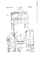
- FIG. 1 is a perspective of a gas range constructed in accordance wit-l1 ⁇ this invention.- y
- Fig. 2 is a sectional elevation'throughI one F end of the same, the section being taken ap.-
- Fig. 3 is a sectional elevation through the gas ranges and vand particularly to the construction cooking top 3.
- Flg. 4 is an inside elevation of the cabinet wall at the left handv end of Fig. 1..
- Fig. 5 is a plan of the same.
- Fig. 6 is anlinside elevation site end wall of the cabinet.
- Fig. 7 is a plan of the same; and Fig. 8 is a fragmentary vertical section showing a slightly modified form of end wall anchoring means. i i
- the gas range is of the cabinet type, with the compartment 2 arranged 'at one end of the along vits forward and outer end edges is provided with a depending Harige 4, and also along the outer end edge with depending lugs 5 which are .spaced inwardly somewhat from the ange. 4, see- Fig. 2. 1
- the wall 6 at the left hand end of the cabinet extends 'between the depending flanges 4 and 5,- Fig; 2, and may be secured to the lugs 5 in any suitable manner, such as by bolts 7.
- the lower edge portion of the wall 6 is .doubled or folded back upon its inner face,l tance, then is bent away from the inner face of the end wall a short distance, and then downwardly to formv a hook 9 which is dewhich forms the bottom of the cabinet.
- the member 10 may be formed of angle strips, each of which has one arm vertical rear vertical edge of the wall 6 is provided with a :Bange v11 which extend'ssomewhat of the oppoas at 8, (Fig. 2) -for a short disoven compartment land the broilerv tachably engageable over a frame member 10 along and may be secured to, the rear wall or frame of the cabinet in any'suitable manner, such as by bolts 12 which pass through the rear wall and the flange'll'.
- the flanges 13 and 14 may be also provided with a flange 13 extending toward the opposite end of the cabinet, and then bent inwardly and parallel to along the forward edge of this end wall may ⁇ serve as one forward corner or post of the cabinet, and because of its angular shape,
- edge is bent lupwardly along its inner face
- the rear verticaledge of the wall has a flange 17 which extends a short distance along the rear wall ofthe cabinet, and may be connected to the rear wall 18 of the cabinet in anv suitab e manner. such as by bolts 19.
- the upper horizontal edge of the wall 15 is provided with a flange 20 which fits against a similar flange 21 of a dome or cap 22 which forms the top of the cabinet at thek oven end thereof. Suitable means. such as bolts 23. may be passed through the flanges 20 and 21 toV connect them.
- the forward vertical edge of the wall 15 may also be provided with a flange 24 against which the door frame 25 (Fig. 1') at the oven end of the cabinet may be fitted and secured, as usual in this type of gas range.
- a wall 25 which may be either end wall i of the cabinet, may have separate hooks or bent strips 26 attached to its inner face ⁇ such as by spot welding, and these hooks 26engage with the angle strips 10 of the framein the same manner as the hooks 9 and 16.
- a gas range comprising a bottom frame, a top member, a wall panel of sheet metal having a depending hook portion projecting from its inner face adjacent its lower edge, and extending approximately parallel to said face and hooked to said frame, the forwardy vertical edge of said panel being turned toward the opposite vertical wall of the range,
- a cabinet range having a cooking top frame, a lower frame approximatelyparallel to said cooking top frame and spaced therefrom2 said cooking top frame having a dependmg flange along its side and forward edges, a rear wall permanently connecting said frames, an end wall having its upper edge fastened to said cooking top frame beneath said flange and having its rear vertical side edge flanged laterally and secured to said rear wall, and having its forward edge flanged first at a right angle toward the opposite end of the range and then rearwardly toward said rear wall to form a corner post for an opening in the front of the range, the lower edge of said end wall extending to the bottom edge of saidfbottom frame to conceal the same, and having a hook extending from its innerV face at a point spaced above the bottom and hooking over said bottom frame whereby the visible area of said end wall will be free of fastening means.
- An end wall forming part of a cabinet range comprising a sheet of metal having its lower end edge bent inwardly and backwardly upon itself and then depending in space d relation to said wall to provide a dependmg hook on the inner face ofsaid wall at a point spaced above the bottom thereof, and having itsvertical side edges flanged at right angles thereto and having its upper edge substantially flat.
- a cabinet-range having a bottom frame member of angle iron strips, with one arm of each angle strip forming an upwardly extendmg flange on the outer periphery of the frame, a-top frame member having a flange concealed beneath the same, a rear wall connected between said frame members, an end lwall connected at its upper edge to said concealed ange and having its vertical side edges flanged toward the opposite end wall, the rear vertical ange of the end wall being secured to said rear wall, the ⁇ lower edge of said end wall having a depending hook from its inner face at a point spaced above the lower edge thereofl and hooking over the upstanding arm of that end of Said bottom frame membeg'with said end Wall extending to the bottom of the outer face of said upright ange and concealing the same.
Landscapes
- Engineering & Computer Science (AREA)
- Chemical & Material Sciences (AREA)
- Combustion & Propulsion (AREA)
- Mechanical Engineering (AREA)
- General Engineering & Computer Science (AREA)
- Baking, Grill, Roasting (AREA)
Description
April 19, 1932. s. s. JEWETT GAS RANGE Filed May 9, 1930 A SHERMAN present a smooth and unbroken exposed visi 'Patented Apr. 19, 1932 A,UNrrED STATE-s PATENT oI-Flca s. JFWET'T, oF BUFFALO, NEW YORK, AssIGNoR To JEWFTT e comm, .A Vor BUFFALO, NEW YORK, A conronamroNoF NEW Yoan eas FYANGE appncation mea May' e,` 1930.I serial Na. 451,007.
Y This *invention relates* to the like, of the cabinet portions thereof. The cabinets of gas ranges arev'comnmonly formed of metal parts having their exposed surfaces enameled andthe appearance of such surfaces would be injured by the use of visible screws, bolts, orother similar fastening devices passing through apertures in the.en'- ameled walls tosecure them-to Aother parts of the stove. The presence of exposed bolt Aheads orv the like, would also make diicult the cleaning of the-exposed surfaces of such; a gas range. One object of this invention is to improve the appearance, durability and construction of the cabinets of gas ranges and the like.
Another object of the invention is to pro-` vide an improved construction for bodies of cabinetgasranges and the like, which will ble surface; with which some of thewalls may be securely anchored and attached in a simple manner to the other walls and frame of v,the range; with which the visible partsof the' end walls will be free of visible attaching means; with which'the labor of cleaning such end walls will be reduceclto a minimum; with which tendency of enameled surfaces to chip' will be reduced; and which will be relatively simple and inexpensive in construction, and attractive in appearance.
Various other objects and advantages will be apparent from the following description of an embodiment of an invention, and the novel features will be partzularly pointed outhereinafter in connection with the appended claims. .c
-In the accompanyingI drawings, Fig. 1 is a perspective of a gas range constructed in accordance wit-l1 `this invention.- y
Fig. 2 is a sectional elevation'throughI one F end of the same, the section being taken ap.-
proximately along the linel2-2 of Fig. 1.
Fig. 3 is a sectional elevation through the gas ranges and vand particularly to the construction cooking top 3. The cooking top,
'other end of the same, the section being taken approximately along the line 3-3 of Fig. 1.
Flg. 4 is an inside elevation of the cabinet wall at the left handv end of Fig. 1..
Fig. 5 is a plan of the same. Fig. 6 is anlinside elevation site end wall of the cabinet.
Fig. 7 is a plan of the same; and Fig. 8 is a fragmentary vertical section showing a slightly modified form of end wall anchoring means. i i
rIn the illustrated embodiment of the -invention, the gas range is of the cabinet type, with the compartment 2 arranged 'at one end of the along vits forward and outer end edges is provided with a depending Harige 4, and also along the outer end edge with depending lugs 5 which are .spaced inwardly somewhat from the ange. 4, see- Fig. 2. 1
The wall 6 at the left hand end of the cabinet extends 'between the depending flanges 4 and 5,- Fig; 2, and may be secured to the lugs 5 in any suitable manner, such as by bolts 7. The lower edge portion of the wall 6 is .doubled or folded back upon its inner face,l tance, then is bent away from the inner face of the end wall a short distance, and then downwardly to formv a hook 9 which is dewhich forms the bottom of the cabinet.
.The member 10 may be formed of angle strips, each of which has one arm vertical rear vertical edge of the wall 6 is provided with a :Bange v11 which extend'ssomewhat of the oppoas at 8, (Fig. 2) -for a short disoven compartment land the broilerv tachably engageable over a frame member 10 along and may be secured to, the rear wall or frame of the cabinet in any'suitable manner, such as by bolts 12 which pass through the rear wall and the flange'll'.
The forwardfvertical edge of the wall 6` the plane of the end wall to form anotherv 'flange 14, Fig. 5. The flanges 13 and 14 may be also provided with a flange 13 extending toward the opposite end of the cabinet, and then bent inwardly and parallel to along the forward edge of this end wall may ``serve as one forward corner or post of the cabinet, and because of its angular shape,
. edge is bent lupwardly along its inner face,
then normally to the wall` and then downwardly to form a hook 16 similar to the hook 9 of the wall 6.' The hook 16 "engages over the upstanding arm of the angle strip 10. The rear verticaledge of the wall has a flange 17 which extends a short distance along the rear wall ofthe cabinet, and may be connected to the rear wall 18 of the cabinet in anv suitab e manner. such as by bolts 19.
The upper horizontal edge of the wall 15 is provided with a flange 20 which fits against a similar flange 21 of a dome or cap 22 which forms the top of the cabinet at thek oven end thereof. Suitable means. such as bolts 23. may be passed through the flanges 20 and 21 toV connect them. The forward vertical edge of the wall 15 may also be provided with a flange 24 against which the door frame 25 (Fig. 1') at the oven end of the cabinet may be fitted and secured, as usual in this type of gas range.
Instead of having the hooks 9 and 16 f formed bv bending the lower edge portions of the end walls. these walls may have simi lar hooks provided in any desired manner, upon their inner faces. For example` in Fig. 8. a wall 25, which may be either end wall i of the cabinet, may have separate hooks or bent strips 26 attached to its inner face` such as by spot welding, and these hooks 26engage with the angle strips 10 of the framein the same manner as the hooks 9 and 16.
' It will be observed that the visible or exposed end faces of both end walls of the cabinet are free of proiections such as bolt heads. and hence when the outer faces of such end walls are enameled they present an attractive appearance and smooth and unbroken surface to facilitate cleaning. The lower edges of the end walls 4are securely anchored tothe bottom ,frame 10 of the cabinet by the hooks 9 and 16, vor 26 and the ,end walls effectively conceal the bottom frame member The end Vwalls having the hooks 9, 16 or mainder of the range by the bolts 7, 12, 19, and 23. l
The method of fastening the end pieces 6 and 15 to the back and front, in addition to the security provided by the bottom fold gives sufficient rigidity to the stove or range when it is fully assembled.
It will be obvious that various changes in the details, which have been herein described and illustrated for the purpose of explaining the nature of the invention, may be made by those skilled in the art within the principle and scope of the invention as expressed in the appended claims. v
Claims: 1. A gas range comprising a bottom frame, a top member, a wall panel of sheet metal having a depending hook portion projecting from its inner face adjacent its lower edge, and extending approximately parallel to said face and hooked to said frame, the forwardy vertical edge of said panel being turned toward the opposite vertical wall of the range,
and then rearwardly in spaced parallel relation to itself to form a front column, and means for attaching the upper edge portion of said panel to said top member.
2.. A cabinet range having a cooking top frame, a lower frame approximatelyparallel to said cooking top frame and spaced therefrom2 said cooking top frame having a dependmg flange along its side and forward edges, a rear wall permanently connecting said frames, an end wall having its upper edge fastened to said cooking top frame beneath said flange and having its rear vertical side edge flanged laterally and secured to said rear wall, and having its forward edge flanged first at a right angle toward the opposite end of the range and then rearwardly toward said rear wall to form a corner post for an opening in the front of the range, the lower edge of said end wall extending to the bottom edge of saidfbottom frame to conceal the same, and having a hook extending from its innerV face at a point spaced above the bottom and hooking over said bottom frame whereby the visible area of said end wall will be free of fastening means.
3. An end wall forming part of a cabinet range comprising a sheet of metal having its lower end edge bent inwardly and backwardly upon itself and then depending in space d relation to said wall to provide a dependmg hook on the inner face ofsaid wall at a point spaced above the bottom thereof, and having itsvertical side edges flanged at right angles thereto and having its upper edge substantially flat.
4. A cabinet-range having a bottom frame member of angle iron strips, with one arm of each angle strip forming an upwardly extendmg flange on the outer periphery of the frame, a-top frame member having a flange concealed beneath the same, a rear wall connected between said frame members, an end lwall connected at its upper edge to said concealed ange and having its vertical side edges flanged toward the opposite end wall, the rear vertical ange of the end wall being secured to said rear wall, the `lower edge of said end wall having a depending hook from its inner face at a point spaced above the lower edge thereofl and hooking over the upstanding arm of that end of Said bottom frame membeg'with said end Wall extending to the bottom of the outer face of said upright ange and concealing the same.
SHERMAN S. JEWETT.
Priority Applications (1)
| Application Number | Priority Date | Filing Date | Title |
|---|---|---|---|
| US451007A US1854743A (en) | 1930-05-09 | 1930-05-09 | Gas range |
Applications Claiming Priority (1)
| Application Number | Priority Date | Filing Date | Title |
|---|---|---|---|
| US451007A US1854743A (en) | 1930-05-09 | 1930-05-09 | Gas range |
Publications (1)
| Publication Number | Publication Date |
|---|---|
| US1854743A true US1854743A (en) | 1932-04-19 |
Family
ID=23790412
Family Applications (1)
| Application Number | Title | Priority Date | Filing Date |
|---|---|---|---|
| US451007A Expired - Lifetime US1854743A (en) | 1930-05-09 | 1930-05-09 | Gas range |
Country Status (1)
| Country | Link |
|---|---|
| US (1) | US1854743A (en) |
Cited By (1)
| Publication number | Priority date | Publication date | Assignee | Title |
|---|---|---|---|---|
| US11185953B2 (en) * | 2017-12-15 | 2021-11-30 | Midea Group Co., Ltd. | Service panel for a cooking appliance |
-
1930
- 1930-05-09 US US451007A patent/US1854743A/en not_active Expired - Lifetime
Cited By (1)
| Publication number | Priority date | Publication date | Assignee | Title |
|---|---|---|---|---|
| US11185953B2 (en) * | 2017-12-15 | 2021-11-30 | Midea Group Co., Ltd. | Service panel for a cooking appliance |
Similar Documents
| Publication | Publication Date | Title |
|---|---|---|
| US2424217A (en) | Sheet metal storage cabinet | |
| US1952111A (en) | Shelving construction | |
| US2295915A (en) | Cabinet construction for ranges and the like | |
| US3186782A (en) | Knock-down cabinet construction | |
| US2485359A (en) | Cooking stove or range | |
| US1836901A (en) | Metallic cabinet structure | |
| US1770500A (en) | Metal-table construction | |
| US1854743A (en) | Gas range | |
| US2270710A (en) | Cabinet construction for ranges and the like | |
| US1079507A (en) | Metallic kitchen-cabinet. | |
| US1724882A (en) | Base for refrigerator cabinets | |
| US2357025A (en) | Reinforced sheet metal cabinet construction | |
| US2622584A (en) | Stove construction | |
| US1815346A (en) | Furnace register | |
| US809497A (en) | Fire-resisting cabinet. | |
| US1869807A (en) | Wall cabinet | |
| US1509853A (en) | Table | |
| US1907414A (en) | Oven of gas and electric ranges | |
| US2185953A (en) | Refrigerator | |
| US2091355A (en) | Goods display holder | |
| US2322407A (en) | Tub construction | |
| US2215315A (en) | Car door | |
| US1633089A (en) | Splasher back for stoves | |
| US1315039A (en) | Stove door | |
| US2171852A (en) | Range base |