US1854718A - Babbitting machine - Google Patents
Babbitting machine Download PDFInfo
- Publication number
- US1854718A US1854718A US481956A US48195630A US1854718A US 1854718 A US1854718 A US 1854718A US 481956 A US481956 A US 481956A US 48195630 A US48195630 A US 48195630A US 1854718 A US1854718 A US 1854718A
- Authority
- US
- United States
- Prior art keywords
- drum
- connecting rod
- plates
- bearing
- machine
- Prior art date
- Legal status (The legal status is an assumption and is not a legal conclusion. Google has not performed a legal analysis and makes no representation as to the accuracy of the status listed.)
- Expired - Lifetime
Links
Images

Classifications
-
- B—PERFORMING OPERATIONS; TRANSPORTING
- B22—CASTING; POWDER METALLURGY
- B22D—CASTING OF METALS; CASTING OF OTHER SUBSTANCES BY THE SAME PROCESSES OR DEVICES
- B22D19/00—Casting in, on, or around objects which form part of the product
- B22D19/08—Casting in, on, or around objects which form part of the product for building-up linings or coverings, e.g. of anti-frictional metal
- B22D19/085—Casting in, on, or around objects which form part of the product for building-up linings or coverings, e.g. of anti-frictional metal of anti-frictional metal
Definitions
- My invention relates to machines for babbitting connecting rods and certain objects of the invention are to provide a machine whereby the bearing portions of connecting rods may be readily and automatically held in positlon and in readiness for babbitting. Further objects of the invention are to pro vide means whereby the connecting rod bearings may be automatically ejected'from the machine. Still further objects are to provide adjustable means whereby the device is adapted for babbitting all types and sizes of connecting rods.
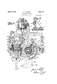
- Figure 1 is a top plan view of the machlne as a whole
- Fig. 2 is a View in front elevation of the same
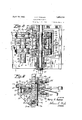
- Fig. 3 is a view in vertical section taken substantially on a broken line 3, 3 of Fig. 9;
- Fig. 4 is a detail view in perspective of one of the clutch members
- Fig. 5 is aview in end elevation of the machine
- Fig. 6 is a view in vertical section taken on a broken line 6, 6 of Fig. 1;
- Fig. '7 is an enlarged view in horizontal section taken on a broken line 7, 7 of Fig. 8 and showing the movement of certain parts in dotted lines;
- Fig. 8 is an enlarged view, partly in elevation, and partly in vertical section taken on a broken line 8, 8 of Fig. 1;
- Fig. 9 is a viewin vertical section taken on a broken line 9, 9 of Fig. 8.
- the numeral 5 designates a horizontal base plate upon which the machine is supported.
- Said base plate has an offset portion 6 and an upstanding face plate 7 secured to or integral with the front edge of said offset portion, and wing bracket portions 8 extend rearward from the vertical edges of the face plate.
- Said face plate is provided with a large opening 9 for reasons hereinafter apparent;
- a bracket bearing 10 is secured to the base plate 5 and a cylinder 11 is pivoted at 12 to said bracket.
- Said cylinder has a piston 13 mounted therein with a rod 14 projecting exteriorly therefrom and having a rack bar portion 15 at its outer end.
- Said rod and bar is arranged to slidably move back and forth in a dovetail groove 16 provided in the side of a bracket member 17 that is fixedly secured to the base plate and as shown in detail in Fig. 6.
- Said cylinder has entry ports at either end with hose 18 and 19 respectively connected thereto and leading to an air compression tank or the like.
- Each of said hose may be provided with a foot lever whereby air may be admitted through valves to either end of the cylinder to force the piston and its rod outwardly or inwardly as desired.
- the air tank and foot levers are not shown in the drawings and it will be understood that other means may be used for causing the rack bar to move back and forth.
- the teeth of the rack bar 15 mesh with the teeth 20 formed on the peripheral edge of a segmental drum member 21.
- said drum member is hollow and is supported in the large opening 9 of the face plate 7 on a vertical shaft 22 whereby it mayeither turn on or with said shaft as hereinafter set forth.
- the upper end of said shaft is journaled through the edge portion of the face plate while its lower end has its bearing in a nut 23 threaded into said face plate whereby any slack caused by wear or the like may be taken up as will be understood.
- a hearing plate 24 is fixed to this end portion of the shaft and a ball thrust bearing 25 may be installed thereon with a projecting hub portion 26 of the segmental. drum member fitting into said bearing.
- a coiled spring 27 may be installed around said hub between the bearing and segmental drum in order to resiliently support the weight and permit slight up and down movement of the drum.
- the segmental drum 21 has a clutch member 28 secured by screws 29 to its upper and inner side and a corresponding clutch member 30 secured to its lower inner side by screws 31, one of which clutch members is shown in detail in Fig. 4.
- the upper clutch member has a complementary clutch member 32 coacting therewith and revolubly mounted on the vertical shaft 22 while the lower clutch member has a corresponding clutch member 33 arranged in mesh therewith.
- Said last named two clutch members are respectively provided with an inwardly projecting female hub portion 34 and a male hub portion 35 telescopically projecting into said female hub.
- a coiled spring 36 is interposed between the clutch members and around said hubs whereby they are yieldingly held in engagement with the clutch members that are secured to the segmental drum member.
- An arm 37 is secured by screws 38 to the clutch member 32 and a corresponding arm 1 39 is secured by screws 40 to the clutch member 33.
- the head portions 41 and 42 respectively of said arms are semi-cylindrically concave to receive semi-cylindrical plates 43 and 44 that are secured therein by screws or bolts 45.
- the concave portions of said plates are adapted to register with a semicylindrical coremcmber 46 that is secured vertically to the face plate 7 by screws or other fastenings 47. It will be understood that said plates and cores are made in varin-ri uu ous sizes to fit the different sizes of connecting rods.
- connection rods which fits around the crank pin of a crankshaft is made in two equal parts that are held together by bolts as is well understood, and my device is adapted for babbitting both of said parts.
- either of said parts is placed over the core member 46 with its bolt holes fitting over small studs 48 set in plates that are held in spaced relation against the outside of the face plate 7 by means hereinafter described.
- Compressed air is then admitted through the hose 18 of the cylinder 11 and the rack bar 15 will carry the segmental drum 21 around whereby the clutch members hereinbefore described will carry the arms 37 and 39 from the dotted position to the full line position as clearly shown in Fig. 7
- the head plates 43 and 44 are selected to snugly fit the core member 46 that is used in order to completely close the space between the side edges of the connecting rod bearing and the core member.
- a core member is used that is slightly smaller than the crank pin to which the particular connecting rod belongs.
- A. V-shaped slot or groove 49 is provided in the upper head plate 43 through which the Babbitt metal is poured into the hearing or rather into the space between the bearing and the core member.
- a semi-annular groove 50 on the under and upper side of the head plates, as shown in Fig. 9, provides means whereby a collar or annular shoulder is formed on either side of the hearing when the metal is poured which may, of course, be dressed off after the bearing is removed from the device.
- Said mechanism comprises a shelf bracket 52 that is fastened by screws 53 to the face plate 7.
- Link plates 54 and 55 are respectively pivoted in spaced relation at 56 and 57 to raised supports on said shelf.
- the outer ends of said link plates are respectively pivoted at 58 and 59 to a bar member 60 while their inner ends are pivoted at 61 and 62 to a bar 63.
- the bar 63 is provided with a turned down lip 64 which slides in a slot 65 and moves a member 66 forward which is siidably mounted on the shelf.
- the slidable member 66 is provided with a slot 67 wherein the square depending heads 68 and 69 of pins 70 and 71 are slidably held. Said pins are slidably disposed in sleeves T2 and 73 respectively that are adjustably housed in slots 7 4 and 75 through the face plate 7.
- the inner ends of said sleeves are provided with flanges that rest against bearing plates 76 and 77 that bear against the inside of said face plate and cover said slots, while the outer ends of said sleeves are threaded is made by loosening the sleeves and slidably moving the plates which carry the pins and studs toward or away from each other.
- a dog 80 is pivoted at 81 to the segmental drum 21 and the finger end of said dog, that is held in an outward position by a spring 82, is arranged to engage the extended end of the link plate 54: as most clearly shown in Fig. 7 of the drawings.
- said drum is moved to the dotted position the contact of said dog with said link plate carries the bar members 60 and 63 to the dotted positions.
- he lip 64 of the latter bar member will move the slidable member 66 forward thus pushing the pins 70 and 7-1 outwardly against the connecting rod bearing and kicking it oil? from the core member 46 and the studs 18.
- the bar 60 is provided with a curved end portion 83 that is adapted to be engaged by a screw 84: that is adjustably set in a lug 85 on the segmental drum 21.
- a screw 84 that is adjustably set in a lug 85 on the segmental drum 21.
- a machine for babbitting connecting rods having in combination a frame with hearing plates, a revoluble drum member, means for causing reciprocative rotary movement or the drum, detachable core members, means for retaining connecting rod bearin portions in placeon the core members, space apart arms actuated by the drum, detachable head plates for the arms adapted to be moved by the drum into cooperative engagement with the core members and oneitherside of a connecting rod portion positioned on the core membersand clutch connections betweenrthe arms and drum for .moving-the head plates into secure engagement with the sides of connecting rod bearings.
- a machine for babbitting connecting rods having in combination a frame with bearing plates, a 'revoluble drum member, means for causing reciprocative rotary movement of the drum, a detachable core member, means for retaining connecting rod bearing portions in place on the core member, spaced apart arms actuated by the drum, detachable head plates for the arms adapted to be moved by the drum into cooperative engagement with the core member and on either side of a connecting rod portion positioned on the core member, clutch connections between the arms and the drum whereby the head plates may be moved into secure engagement with the sides of connecting rod bearings positioned on the core after the head plates have been moved to engagement with the core member, and spring means for yieldingly retaining said clutches in cooperative engagement.
- a machine for babbitting connecting rods having in combination a frame with hearing plates, a revoluble drum member, means for causing reciprocative rotary movement of the drum, a detachable core member,
- ⁇ means for retaining connecting rod bearing portions in place against the core member, spaced apart arms actuated by the drum, detachable head plates for the arms adapted to be moved by the drum into engagement with the core member and on either side of a connecting rod bearing positioned on the core member, clutch connectionsbetween the arms and the drum whereby the head plates are moved into snug engagement with the sides of connecting rod bearings positioned on the core after the head plates have been moved to engagement with said core, spring means for yieldingly retaining said clutches in oooperative engagement, and means for ejecting connecting rod bearings from the machine.
- a machine for babbitting connecting rods having in combination a frame with hearing plates, a revoluble drum member, means for causing reciprocative rotary movement of the drum, a detachable core member, means for retaining connecting rod hearings in place against the core member, spaced apart arms actuated by the drum, detachable head plates for the arms adapted to be moved by the drum into engagement with the core member andon either side of a connecting rod bearing positioned on the core member, clutch connections between the arms and the drum whereby the head plates are moved into secure engagement with the sides of connecting rod bearings after the head plates have been revolubly moved into engagement with said core, spring means for yieldingly retaining said clutches in cooperative engagement, means for ejecting connecting rods from the machine, and adjusting means for said ejecting and retaining means whereby connecting rod bearings of various sizes may be retained and ejected by the machine.
Landscapes
- Engineering & Computer Science (AREA)
- Mechanical Engineering (AREA)
- Mechanical Operated Clutches (AREA)
Description
April 19, 1932. H. H. RAWSON 1,854,718
BABBITTING MACHINE Filed Sept. 15, 1930 3 Sheets-Sheet l 4 r M f 2 7- w [NVEN TOR. Harry /7. Ra wson A TTORNEY.
April 19, 1932. H. H. RAWSON 1,854,718
BABBITTING MACHINE Fi-led Sept. 15, l950 5 Sheets-Sheet 2 I jes IN VEN TOR.
: I 7 Harry h. fiarrsqn izwzsw ATTORNEY.
Patented Apr. 19, 1932 UNITED STATES PATENT OFFICE HARRY H. BAWSON, OE SPOKANE, WASHINGTON, ASSIGNOR T WASHINGTON MA- CHINERY & SUPPLY COMPANY, OF SPOKANE, WASl-IINGTON .BABBITTING MACHINE Application filed September 15,1930. Serial No. 481,956.
My invention relates to machines for babbitting connecting rods and certain objects of the invention are to provide a machine whereby the bearing portions of connecting rods may be readily and automatically held in positlon and in readiness for babbitting. Further objects of the invention are to pro vide means whereby the connecting rod bearings may be automatically ejected'from the machine. Still further objects are to provide adjustable means whereby the device is adapted for babbitting all types and sizes of connecting rods.
With the above and other objects in Viewv which will appear as the description proceeds, the invention consists of the novel construction, adaptation, combination, and arrangement of parts hereinafter described and claimed. These objects are accomplished by devices illustrated in the accompanying drawings; wherein:
Figure 1 is a top plan view of the machlne as a whole;
Fig. 2 is a View in front elevation of the same;
Fig. 3 is a view in vertical section taken substantially on a broken line 3, 3 of Fig. 9;
Fig. 4 is a detail view in perspective of one of the clutch members;
Fig. 5 is aview in end elevation of the machine;
Fig. 6 is a view in vertical section taken on a broken line 6, 6 of Fig. 1;
Fig. '7 is an enlarged view in horizontal section taken on a broken line 7, 7 of Fig. 8 and showing the movement of certain parts in dotted lines;
Fig. 8 is an enlarged view, partly in elevation, and partly in vertical section taken on a broken line 8, 8 of Fig. 1; and
Fig. 9 is a viewin vertical section taken on a broken line 9, 9 of Fig. 8.
Referring to the drawings throughout which like reference numerals indicate like parts, the numeral 5 designates a horizontal base plate upon which the machine is supported. Said base plate has an offset portion 6 and an upstanding face plate 7 secured to or integral with the front edge of said offset portion, and wing bracket portions 8 extend rearward from the vertical edges of the face plate. Said face plate is provided with a large opening 9 for reasons hereinafter apparent;
A bracket bearing 10 is secured to the base plate 5 and a cylinder 11 is pivoted at 12 to said bracket. Said cylinder has a piston 13 mounted therein with a rod 14 projecting exteriorly therefrom and having a rack bar portion 15 at its outer end. .Said rod and bar is arranged to slidably move back and forth in a dovetail groove 16 provided in the side of a bracket member 17 that is fixedly secured to the base plate and as shown in detail in Fig. 6. Said cylinder has entry ports at either end with hose 18 and 19 respectively connected thereto and leading to an air compression tank or the like. Each of said hose may be provided with a foot lever whereby air may be admitted through valves to either end of the cylinder to force the piston and its rod outwardly or inwardly as desired. The air tank and foot levers are not shown in the drawings and it will be understood that other means may be used for causing the rack bar to move back and forth.
The teeth of the rack bar 15 mesh with the teeth 20 formed on the peripheral edge of a segmental drum member 21. As shown in'Figs. 7 and 8, said drum member is hollow and is supported in the large opening 9 of the face plate 7 on a vertical shaft 22 whereby it mayeither turn on or with said shaft as hereinafter set forth. The upper end of said shaft is journaled through the edge portion of the face plate while its lower end has its bearing in a nut 23 threaded into said face plate whereby any slack caused by wear or the like may be taken up as will be understood. A hearing plate 24 is fixed to this end portion of the shaft and a ball thrust bearing 25 may be installed thereon with a projecting hub portion 26 of the segmental. drum member fitting into said bearing. As most clearly shown in Fig. 8, a coiled spring 27 may be installed around said hub between the bearing and segmental drum in order to resiliently support the weight and permit slight up and down movement of the drum.
The segmental drum 21 has a clutch member 28 secured by screws 29 to its upper and inner side and a corresponding clutch member 30 secured to its lower inner side by screws 31, one of which clutch members is shown in detail in Fig. 4. The upper clutch member has a complementary clutch member 32 coacting therewith and revolubly mounted on the vertical shaft 22 while the lower clutch member has a corresponding clutch member 33 arranged in mesh therewith. Said last named two clutch members are respectively provided with an inwardly projecting female hub portion 34 and a male hub portion 35 telescopically projecting into said female hub. A coiled spring 36 is interposed between the clutch members and around said hubs whereby they are yieldingly held in engagement with the clutch members that are secured to the segmental drum member.
An arm 37 is secured by screws 38 to the clutch member 32 and a corresponding arm 1 39 is secured by screws 40 to the clutch member 33. The head portions 41 and 42 respectively of said arms are semi-cylindrically concave to receive semi-cylindrical plates 43 and 44 that are secured therein by screws or bolts 45. The concave portions of said plates are adapted to register with a semicylindrical coremcmber 46 that is secured vertically to the face plate 7 by screws or other fastenings 47. It will be understood that said plates and cores are made in varin-ri uu ous sizes to fit the different sizes of connecting rods.
The bearing portion of connecting rods which fits around the crank pin of a crankshaft is made in two equal parts that are held together by bolts as is well understood, and my device is adapted for babbitting both of said parts. After removing the bolts, either of said parts is placed over the core member 46 with its bolt holes fitting over small studs 48 set in plates that are held in spaced relation against the outside of the face plate 7 by means hereinafter described. Compressed air is then admitted through the hose 18 of the cylinder 11 and the rack bar 15 will carry the segmental drum 21 around whereby the clutch members hereinbefore described will carry the arms 37 and 39 from the dotted position to the full line position as clearly shown in Fig. 7
lVhen the arms 37 and 39 close they will carry the head plates 43 and 44 just clear of the outer edges or sides of the connecting rod bearing due to the spring 36 retaining said arms in a spread apart position as the head plates close down u on the core member 46. After said plates have closed down upon said core the machine will continue to turn causing the clutch members 28 and 30 to force the clutch members32 and 33 and their arms toward each other and thus closing their head plates securely against the outer or side edges of the connecting rod bearing as clearly shown in Fig. 9 of the drawings.
The head plates 43 and 44 are selected to snugly fit the core member 46 that is used in order to completely close the space between the side edges of the connecting rod bearing and the core member. A core member is used that is slightly smaller than the crank pin to which the particular connecting rod belongs. A. V-shaped slot or groove 49 is provided in the upper head plate 43 through which the Babbitt metal is poured into the hearing or rather into the space between the bearing and the core member. A semi-annular groove 50 on the under and upper side of the head plates, as shown in Fig. 9, provides means whereby a collar or annular shoulder is formed on either side of the hearing when the metal is poured which may, of course, be dressed off after the bearing is removed from the device.
When pouring the Babbitt metal gas is always present and forms objectionable bubbles within the bearing. To eliminate this I have found it advisable to thoroughly tamp or poke the metal within the bearing while still in the molten state with a wire or the like and to play a gas jet upon the molten metal at the same time which burns out the gas and thus removes the bubbles. T he wedge shaped metal portion left by the slot or groove may, of course, be scraped back into the supply of molten metal. Before pouring the metal the oil hole or holes through the bearing may be plugged with a piece of wire 51 as shown in Fig. 9
For the purpose of ejecting or kicking off the connecting rod after it has been babbitted, I have provided mechanism that is shown most clearly in Figs. 3, 7 and 9 of the drawings. Said mechanism comprises a shelf bracket 52 that is fastened by screws 53 to the face plate 7. Link plates 54 and 55 are respectively pivoted in spaced relation at 56 and 57 to raised supports on said shelf. The outer ends of said link plates are respectively pivoted at 58 and 59 to a bar member 60 while their inner ends are pivoted at 61 and 62 to a bar 63. The bar 63 is provided with a turned down lip 64 which slides in a slot 65 and moves a member 66 forward which is siidably mounted on the shelf.
7 The slidable member 66 is provided with a slot 67 wherein the square depending heads 68 and 69 of pins 70 and 71 are slidably held. Said pins are slidably disposed in sleeves T2 and 73 respectively that are adjustably housed in slots 7 4 and 75 through the face plate 7. The inner ends of said sleeves are provided with flanges that rest against bearing plates 76 and 77 that bear against the inside of said face plate and cover said slots, while the outer ends of said sleeves are threaded is made by loosening the sleeves and slidably moving the plates which carry the pins and studs toward or away from each other.
In the operation of this mechanism for ejecting the finished connecting rod bearings a dog 80 is pivoted at 81 to the segmental drum 21 and the finger end of said dog, that is held in an outward position by a spring 82, is arranged to engage the extended end of the link plate 54: as most clearly shown in Fig. 7 of the drawings. When said drum is moved to the dotted position the contact of said dog with said link plate carries the bar members 60 and 63 to the dotted positions. he lip 64 of the latter bar member will move the slidable member 66 forward thus pushing the pins 70 and 7-1 outwardly against the connecting rod bearing and kicking it oil? from the core member 46 and the studs 18.
The bar 60 is provided with a curved end portion 83 that is adapted to be engaged by a screw 84: that is adjustably set in a lug 85 on the segmental drum 21. After engagement by the dog as hereinbefore set forth the said bar together with its associated elements that are connected therewith will remain in the dotted position until said screw engages the curved end of said bar thus forcing the entire ejecting mechanism back to the full line position in readiness for the next operation. On the reverse or backward movement of the segmental drum the spring will allow the dog to move to the dotted position as it passes under the link plate.
It will now be apparent that I have provided a machine for babbitting connecting rods and the like comprising novel means'for quickly holding connecting rod hearings in place and in readiness to be babbitted, means for automatically ejecting the connecting rod bearings from the machine, and adjustable means for the ejecting mechanism and retaining means together with other novel details of construction and arrangement.
Having thus described my invention, it being understood that minor changes may be resorted to in its construction and arrangement without departing from the scope and spirit of the invention, what I claim and desire to secure by Letters Patent of the United States is 1. A machine for babbitting connecting rods having in combination a frame with hearing plates, a revoluble drum member, means for causing reciprocative rotary movement or the drum, detachable core members, means for retaining connecting rod bearin portions in placeon the core members, space apart arms actuated by the drum, detachable head plates for the arms adapted to be moved by the drum into cooperative engagement with the core members and oneitherside of a connecting rod portion positioned on the core membersand clutch connections betweenrthe arms and drum for .moving-the head plates into secure engagement with the sides of connecting rod bearings.
2. A machine for babbitting connecting rods having in combination a frame with bearing plates, a 'revoluble drum member, means for causing reciprocative rotary movement of the drum, a detachable core member, means for retaining connecting rod bearing portions in place on the core member, spaced apart arms actuated by the drum, detachable head plates for the arms adapted to be moved by the drum into cooperative engagement with the core member and on either side of a connecting rod portion positioned on the core member, clutch connections between the arms and the drum whereby the head plates may be moved into secure engagement with the sides of connecting rod bearings positioned on the core after the head plates have been moved to engagement with the core member, and spring means for yieldingly retaining said clutches in cooperative engagement.
3. A machine for babbitting connecting rods having in combination a frame with hearing plates, a revoluble drum member, means for causing reciprocative rotary movement of the drum, a detachable core member,
\ means for retaining connecting rod bearing portions in place against the core member, spaced apart arms actuated by the drum, detachable head plates for the arms adapted to be moved by the drum into engagement with the core member and on either side of a connecting rod bearing positioned on the core member, clutch connectionsbetween the arms and the drum whereby the head plates are moved into snug engagement with the sides of connecting rod bearings positioned on the core after the head plates have been moved to engagement with said core, spring means for yieldingly retaining said clutches in oooperative engagement, and means for ejecting connecting rod bearings from the machine.
4. A machine for babbitting connecting rods having in combination a frame with hearing plates, a revoluble drum member, means for causing reciprocative rotary movement of the drum, a detachable core member, means for retaining connecting rod hearings in place against the core member, spaced apart arms actuated by the drum, detachable head plates for the arms adapted to be moved by the drum into engagement with the core member andon either side of a connecting rod bearing positioned on the core member, clutch connections between the arms and the drum whereby the head plates are moved into secure engagement with the sides of connecting rod bearings after the head plates have been revolubly moved into engagement with said core, spring means for yieldingly retaining said clutches in cooperative engagement, means for ejecting connecting rods from the machine, and adjusting means for said ejecting and retaining means whereby connecting rod bearings of various sizes may be retained and ejected by the machine.
In testimony whereby I aflix my signature.
HARRY H. RAWS ON.
Priority Applications (1)
| Application Number | Priority Date | Filing Date | Title |
|---|---|---|---|
| US481956A US1854718A (en) | 1930-09-15 | 1930-09-15 | Babbitting machine |
Applications Claiming Priority (1)
| Application Number | Priority Date | Filing Date | Title |
|---|---|---|---|
| US481956A US1854718A (en) | 1930-09-15 | 1930-09-15 | Babbitting machine |
Publications (1)
| Publication Number | Publication Date |
|---|---|
| US1854718A true US1854718A (en) | 1932-04-19 |
Family
ID=23914056
Family Applications (1)
| Application Number | Title | Priority Date | Filing Date |
|---|---|---|---|
| US481956A Expired - Lifetime US1854718A (en) | 1930-09-15 | 1930-09-15 | Babbitting machine |
Country Status (1)
| Country | Link |
|---|---|
| US (1) | US1854718A (en) |
Cited By (1)
| Publication number | Priority date | Publication date | Assignee | Title |
|---|---|---|---|---|
| US2763042A (en) * | 1951-05-25 | 1956-09-18 | American Brake Shoe Co | Apparatus for applying lining to bearings |
-
1930
- 1930-09-15 US US481956A patent/US1854718A/en not_active Expired - Lifetime
Cited By (1)
| Publication number | Priority date | Publication date | Assignee | Title |
|---|---|---|---|---|
| US2763042A (en) * | 1951-05-25 | 1956-09-18 | American Brake Shoe Co | Apparatus for applying lining to bearings |
Similar Documents
| Publication | Publication Date | Title |
|---|---|---|
| FR2531641A1 (en) | DEVICE FOR BLOWING AND SPRAYING THE DIES OF FORGING PRESSES | |
| US1854718A (en) | Babbitting machine | |
| CN105752673A (en) | Iron mold power rollgang device | |
| US3290006A (en) | Pipe pulling device | |
| US2235619A (en) | Mechanical poultry picker | |
| CN102764872A (en) | Horizontal centrifugal casting machine | |
| US2627335A (en) | Flask hoist for foundry molding machines | |
| US4256167A (en) | Apparatus for centrifugal casting | |
| US2415620A (en) | Centrifugally casting machine | |
| US2556147A (en) | Rotatable buck reciprocating head pressing machine | |
| US2686945A (en) | Mold making machine with rollover device | |
| US2126738A (en) | Molding machine | |
| US1762309A (en) | Mat roaster | |
| US2397863A (en) | Tire spreader | |
| US2090784A (en) | Molding machine | |
| US2335401A (en) | Braking mechanism for mobile containers | |
| US1517609A (en) | Casting machine | |
| US2294267A (en) | Starching machine | |
| US2669196A (en) | Device for maintaining alignment between molds and cooperating rotating cores | |
| US1976670A (en) | Shoe sole leveling, shaping, and securing unit | |
| SU39940A1 (en) | Cone forming machine | |
| US1740775A (en) | mofall | |
| US1208788A (en) | Babbitting-machine. | |
| US2217837A (en) | Apparatus for spinning centrifugal molds | |
| CN204338836U (en) | With the taking mechanical hand of smoke discharging function |