US1854712A - Magnetic brake device - Google Patents
Magnetic brake device Download PDFInfo
- Publication number
- US1854712A US1854712A US438141A US43814130A US1854712A US 1854712 A US1854712 A US 1854712A US 438141 A US438141 A US 438141A US 43814130 A US43814130 A US 43814130A US 1854712 A US1854712 A US 1854712A
- Authority
- US
- United States
- Prior art keywords
- chamber
- valve
- pipe
- brake
- passage
- Prior art date
- Legal status (The legal status is an assumption and is not a legal conclusion. Google has not performed a legal analysis and makes no representation as to the accuracy of the status listed.)
- Expired - Lifetime
Links
Images
Classifications
-
- B—PERFORMING OPERATIONS; TRANSPORTING
- B61—RAILWAYS
- B61H—BRAKES OR OTHER RETARDING DEVICES SPECIALLY ADAPTED FOR RAIL VEHICLES; ARRANGEMENT OR DISPOSITION THEREOF IN RAIL VEHICLES
- B61H7/00—Brakes with braking members co-operating with the track
- B61H7/02—Scotch-blocks, skids, or like track-engaging shoes
- B61H7/04—Scotch-blocks, skids, or like track-engaging shoes attached to railway vehicles
- B61H7/06—Skids
- B61H7/08—Skids electromagnetically operated
Definitions
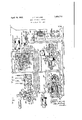
- Figure 1 is a diagrammatic view, mostly ,in section of a combined fluid pressure and magnetic brake apparatus embodying the invention
- Fig. 2 is a development of the brake valve device shown in Fig. 1.
- the switch device 14 may comprise a cylinder 21, containingV a piston 22, having a stem V23, projecting from one side thereof.
- the stem 23 extends through the casing of the switch device 14, and is provided, near its extremity, with a contact member 24, which is suitably insulated from the stem in the manner shown.
- the contact member 24 is preferably in the form of a disc., which is adapted to engageV with the contact 19 and another contact 25y connected to a source of current supply wire 26, to completethe circuit through which the magnetic brake shoe 6 is energized, when the switch device 14 is operated.
- the brake valve device 8 may comprise a casing having a chamber 28, connected to the main reservoir 10 by a passage and pipe 29, and contains a rotary valve 30, which is adapted to be operated by a handle 31.
- the piston chamber 32 is connected to the usual brake pipe 36, and the valve chamber 34 is connected through passage 37 with vthe main reservoir pipe 29.
- the passage 38 leading to the seat of the slide valve 35, is connected to a pipe 39, which leads to the brake cylinder 7
- passage 38 is connectedthrough cavity 40, with passage 41, which leads-to the ⁇ usual straight air pipe 42.
- port 43 registers with apassage 44, leading to the pipe 45, through which the sanding reservoir 11 is charged with fluid under pressure.
- the brake cylinder 7 and the chamber 48 of the pilot valve device 12 are vented to the atmosphere in the usual manner, through pipe 39, passage 38, valve cavity 40 of the emergency valve device 9, passage 41, straight air pipe 42, cavity 70 of the valve 30' ofv the brake valve device 8, and atmospheric exhaust port 71.
- Chamber 55' of the control valve device 13 is charged with fluid under pressure from the main reservoir through pipe 29, chamber 54 of the pilot valve device 12, past the fluted stem 72 of the double beat valve A50, chamber 51, and passage and pipe 59. With the chamber thus charged with fluid under pressure, the piston 56 will be positioned at the right, and valve chamber 57 and' the-reservoir will be charged with fluid under pressure through thel feed groove 74 i-n the usual manner.
- the brake valve When it is desired toy make a service application of the brakes, the brake valve is moved to its service position, thus connecting the main reservoir pipe 29 with the straight air pipe 42, (see Fig. 2).
- the brake cylinder 7 is now supplied with fluid under pressure through the pipe39, and since the chamber 48 is also connected to the brake cylinder pipe 39, such chamber will also be supplied with fluid under pressure.V
- the pressure of the Huid in chamber 48 is not sufficient to move the diaphragm 46v against the pressure of the spring 49, the pilot valve device 12, and the parts controlled thereby will not be operated. But should the pressure of the fluid admitted to the chamber 48, during an application of the brakes, exceed the pressure of they pressure of. the spring 49, then the diaphragm 46 will be flexed toward the right, and the pilot valve device 12 and associated parts will be operated in themanner hereinafter more fully described..
- valve When it is desired toA effect an emergency application of the brakes, the valve is moved to itsy emergency position, thus connecting the pipe 36 with the atmospheric vent port 7l, and the pipe 42v with the main reservoir pipe 29 (see Fig. 2),.v
- Fluid is then vented from piston chamber 32,4 sov that piston 33 is shifted tothe right by the-fiuid pressure in valve chamber 34.
- the valve is alsoshifted, so that cavity 76 connects passage with passage 44.
- Fluid under pressure is then supplied from the sanding reservoir 11,. to the sanding pipe. 66, and also through the pipe 67, past the ball check valve 68 to piston chamber 62.f Piston 22 is thereupon shifted downwardly so that the Contact member 24 closes the circuit tothe magneticbrake shoe 6, thereby energizing the coilsof said shoe.
- Fluid under pressure supplied from the sanding reservoir 11 gradually vents to the atmosphere through the restricted port 69, until the reservoir pressure has. been reduced suiiiciently to. permit the piston 22 to be moved upwardly by the spring 27.
- the circuit ofl the magnetic' brake shoe 6 is then opened. In this way the time in which the coils ⁇ (not shown) of the magnetic' brake shoe 6 are energized islimited in each brake application, so; as to prevent the possible burning out ofthe coils, in case the brakes should be left.
Landscapes
- Physics & Mathematics (AREA)
- Electromagnetism (AREA)
- Engineering & Computer Science (AREA)
- Mechanical Engineering (AREA)
- Braking Systems And Boosters (AREA)
Description
April 19, 1932. 1. c. MOCUNE MAGNETIC BRAKE DEVICE Filed March 22 INVENTOR JOSEPH C MCUNE AT1-OR EY Patented Apr. 19, 1932 UNITED STATES PATENT OFFICE Y JOSEPH c.1v1coUNE, oF nncnwoon, PENNSYLVANIA, ASSIGNOR To THEv wEsTINGHoUsE .AIR BRAKE COMPANY, OF WILMERDINQ PENNSYLVANIA, A CORPORATION 0F l PENNSYLVANIA MAGNETIC BRAKE DEVICE Application inea March a2, 1930. serial No. 438,141.
This invention relates to brakes, and more particularly to a combined fluid pressure and magnetic brake device.
An object of the invention is to provide a combined fluid pressure and magnetic brake apparatus in which the magnetic brake is operated when the brake cylinder pressure exceeds a predetermined amount.
Another object of the invention is to provide an improved brake apparatus of the above type, in which the magnetic brake is adapted to remain inactive, when an ordinary service application of the fluid pressure brakes is effected, and in which the magnetic brake is actuated by means operated when an emergency application of the brakes is effected.
- Another object of the invention is toV provide an improved magnetic brake device of the character mentioned which is relatively simple in construction, and reliable and .eX- act in function under all conditions of service.
The invention also comprises certain new and useful improvements in the: construction, arrangement and combination of the several parts of which it is composed, as will be hereinafter more fully described and claimed. y
In the accompanying drawings; Figure 1 is a diagrammatic view, mostly ,in section of a combined fluid pressure and magnetic brake apparatus embodying the invention and Fig. 2 is a development of the brake valve device shown in Fig. 1.
Referring to the drawings, the apparatus may comprise a magnetic brake 6, brake cylinder 7, brake valve device 8, emergency valve device 9, main reservoir or other source of iiuid under pressure 10, sanding reservoir 11,
The magnetic brake 6 may comprise a shoe which is suspended above the railvby coil springs 16 which are secured at one end to a portion 17 of the car truck. c
The magnetic brakeshoe may be of any approved construction, `and one terminal of the energizing coils thereof `(not shown) is connected to a ground 18, while the other terminal of said magnetcoils is connected to a contact 19 of the switch devicel4, by a wire 20.
The switch device 14 may comprise a cylinder 21, containingV a piston 22, having a stem V23, projecting from one side thereof. The stem 23 extends through the casing of the switch device 14, and is provided, near its extremity, with a contact member 24, which is suitably insulated from the stem in the manner shown. The contact member 24 is preferably in the form of a disc., which is adapted to engageV with the contact 19 and another contact 25y connected to a source of current supply wire 26, to completethe circuit through which the magnetic brake shoe 6 is energized, when the switch device 14 is operated.
Acoil spring 27 in the cylinder 21 urges the piston 22 upwardly, so that the contact member 24 is normally disengaged from the contacts 19 and 25, and the magnetic brake circuit is opened.
The brake valve device 8 may comprise a casing having a chamber 28, connected to the main reservoir 10 by a passage and pipe 29, and contains a rotary valve 30, which is adapted to be operated by a handle 31.
The emergency valve device 9 may comprise a casing having a piston chamber 32, containing a piston 33 and a valve chamber 34, containing Aa slide valve 35 adapted to be 0perated by piston 33.
The piston chamber 32 is connected to the usual brake pipe 36, and the valve chamber 34 is connected through passage 37 with vthe main reservoir pipe 29. The passage 38, leading to the seat of the slide valve 35, is connected to a pipe 39, which leads to the brake cylinder 7 In the release position of the slide valve 35, passage 38 is connectedthrough cavity 40, with passage 41, which leads-to the `usual straight air pipe 42. Also, inrelease position, port 43 registers with apassage 44, leading to the pipe 45, through which the sanding reservoir 11 is charged with fluid under pressure. y
lThe pilot valve device 12 lmay comprise a CIJ flexible diaphragm 46, subject to the opposing fluid pressures in diaphragm chambers 47 and 48, and to the pressure of a coil spring 49, contained in chamber 47, said diaphragm being adapted to operate a double beat valve 50, contained in a chamber 5.1. The double beat valve 50 is normally maintained seated against the seat 52 by a coil spring 53', contained in a chamber 54.
The control valve device4 13 may; comprise a casing having a piston chamber 55, containing a piston 56, and a valve chamber 57, containing a slide valve 58, adapted to operated by said piston. The piston chamber 55 is connected to the chamber 51 of' the pilot valve device 12, throughpipe and passage 59. The valve chamber 57. is connected tothe reservoir 15. by a passage and pipe 61.
When the apparatus is in the release position, as shown in Fig. 1, the brake cylinder 7 and the chamber 48 of the pilot valve device 12 are vented to the atmosphere in the usual manner, through pipe 39, passage 38, valve cavity 40 of the emergency valve device 9, passage 41, straight air pipe 42, cavity 70 of the valve 30' ofv the brake valve device 8, and atmospheric exhaust port 71.
Chamber 55' of the control valve device 13 is charged with fluid under pressure from the main reservoir through pipe 29, chamber 54 of the pilot valve device 12, past the fluted stem 72 of the double beat valve A50, chamber 51, and passage and pipe 59. With the chamber thus charged with fluid under pressure, the piston 56 will be positioned at the right, and valve chamber 57 and' the-reservoir will be charged with fluid under pressure through thel feed groove 74 i-n the usual manner.
With the 'emergency valve 35 in the release position, the sanding reservoir 11 will be charged with fluid under pressure from the main reservoir 10 through pipe 29, passage 37, valve chamber35,.ports 7 5- and 43, passage 44, and pipe 45. i
When it is desired toy make a service application of the brakes, the brake valve is moved to its service position, thus connecting the main reservoir pipe 29 with the straight air pipe 42, (see Fig. 2). The brake cylinder 7 is now supplied with fluid under pressure through the pipe39, and since the chamber 48 is also connected to the brake cylinder pipe 39, such chamber will also be supplied with fluid under pressure.V However, if the pressure of the Huid in chamber 48 is not sufficient to move the diaphragm 46v against the pressure of the spring 49, the pilot valve device 12, and the parts controlled thereby will not be operated. But should the pressure of the fluid admitted to the chamber 48, during an application of the brakes, exceed the pressure of they pressure of. the spring 49, then the diaphragm 46 will be flexed toward the right, and the pilot valve device 12 and associated parts will be operated in themanner hereinafter more fully described..
When it is desired toA effect an emergency application of the brakes, the valve is moved to itsy emergency position, thus connecting the pipe 36 with the atmospheric vent port 7l, and the pipe 42v with the main reservoir pipe 29 (see Fig. 2),.v
Fluid is then vented from piston chamber 32,4 sov that piston 33 is shifted tothe right by the-fiuid pressure in valve chamber 34. The valve is alsoshifted, so that cavity 76 connects passage with passage 44. Fluid under pressure is then supplied from the sanding reservoir 11,. to the sanding pipe. 66, and also through the pipe 67, past the ball check valve 68 to piston chamber 62.f Piston 22 is thereupon shifted downwardly so that the Contact member 24 closes the circuit tothe magneticbrake shoe 6, thereby energizing the coilsof said shoe.
Fluid under pressure supplied from the sanding reservoir 11 gradually vents to the atmosphere through the restricted port 69, until the reservoir pressure has. been reduced suiiiciently to. permit the piston 22 to be moved upwardly by the spring 27. The circuit ofl the magnetic' brake shoe 6 is then opened. In this way the time in which the coils `(not shown) of the magnetic' brake shoe 6 are energized islimited in each brake application, so; as to prevent the possible burning out ofthe coils, in case the brakes should be left. applied for too long a period When the emergency valve 35 is shifted to the righ-t,y in the manner above described, passage 38, at the seat of the slide valve 35, will be uncovered, so that fluid under pressure is supplied to the brake cylinder 7 from the main reservoir 10, through pipe 3.9', as has beenV previously described..
When the brake cylinderv pressure is in creased above a predetermined amount so that the fluid under pressure in chamber 48 deii'ects theL diaphragm 46 toward the right against the pressureof spring 49, the double beat valve will also be shifted from the position shown in Fig. l toward the right, and chamber 51 will be connected with chamber 47, through passage 77.
Fluid is then vented from piston chamber 55 to the atmosphere, through passage and pipe 59, chamber 51, passage 77, chamber 17,V
and vent port 78. The piston 56 of the control valve device 13 is then shifted to the left by the fluid pressure in valve chamber 57. The valve 58 is also shifted, so that the passage 63 at the seat of the valve 58 is uncovered. Fluid under pressure is then supplied from the reservoir 15 to the piston chamber 62, through pipe 61, valve chamber 57, and passage and pipe 63, past the ball check valve 64. The piston 22 is thereupon operated in the manner heretofore described, so that the circuit of the magnetic brake shoe 6 is closed. It will also be understood that the pressure of the fluid in the reservoir 15 will gradually blow down through the atmospheric vent port 69, in the manner heretofore described, so that the circuit of the magnetic brake shoe 6 will be opened after a period of time.
While one illustrative embodiment of the invention has been described in detail, it is not my intention to limit its scope to that embodiment or otherwise than by the terms of the appended claim. Y
Having now described my invention, what I claim as new and desire to secure by Letters Patent, is:
The combination with a brake cylinder, and means for supplying liuid under pressure to the brake cylinder, of a magnetic brake device, a pilot valve device subject to brake cylinder pressure, and operative only when the brake cylinder pressure exceeds a predetermined amount, a pneumatically operated switch device for controlling the circuit of the magnetic brake, a reservoir, and a control valve device adapted to be operated when said pilot valve device is operated for supplying fluid pressure from said reservoir to said switch device.
In testimony whereof I have hereunto set my hand, this 20th day of March, 1930.
JOSEPH C. MCCUNE.
Priority Applications (1)
| Application Number | Priority Date | Filing Date | Title |
|---|---|---|---|
| US438141A US1854712A (en) | 1930-03-22 | 1930-03-22 | Magnetic brake device |
Applications Claiming Priority (1)
| Application Number | Priority Date | Filing Date | Title |
|---|---|---|---|
| US438141A US1854712A (en) | 1930-03-22 | 1930-03-22 | Magnetic brake device |
Publications (1)
| Publication Number | Publication Date |
|---|---|
| US1854712A true US1854712A (en) | 1932-04-19 |
Family
ID=23739406
Family Applications (1)
| Application Number | Title | Priority Date | Filing Date |
|---|---|---|---|
| US438141A Expired - Lifetime US1854712A (en) | 1930-03-22 | 1930-03-22 | Magnetic brake device |
Country Status (1)
| Country | Link |
|---|---|
| US (1) | US1854712A (en) |
-
1930
- 1930-03-22 US US438141A patent/US1854712A/en not_active Expired - Lifetime
Similar Documents
| Publication | Publication Date | Title |
|---|---|---|
| US2068342A (en) | Load brake device | |
| US3118707A (en) | Load modified electric distribution system for brakes | |
| US1854712A (en) | Magnetic brake device | |
| US2726739A (en) | Pneumatic vehicle-brake apparatus | |
| US1486872A (en) | Load-brake device | |
| US2118412A (en) | Combined electric and pneumatic brake | |
| US1816078A (en) | Fluid pressure brake | |
| US1776300A (en) | Electropneumatic brake | |
| GB848111A (en) | Fluid pressure braking system for railway vehicles | |
| US1281801A (en) | Fluid-pressure brake. | |
| US1910543A (en) | Fluid pressure brake | |
| US1956674A (en) | Fluid pressure brake | |
| US2302377A (en) | Air brake | |
| US1797411A (en) | Fluid-pressure brake | |
| US1411368A (en) | Air-brake apparatus | |
| US2678851A (en) | Quick release apparatus for fluid pressure brakes | |
| US1816079A (en) | Fluid pressure brake | |
| US1514999A (en) | Electropneumatic brake | |
| US1657530A (en) | Fluid-pressure brake | |
| US1653133A (en) | Electropneumatic brake | |
| US2115523A (en) | High speed brake equipment | |
| US2398902A (en) | Brake cylinder venting apparatus | |
| US1601583A (en) | Air-brake apparatus | |
| US1588610A (en) | Electromagnetic brake valve | |
| US1720266A (en) | Variable-load apparatus |