US1411368A - Air-brake apparatus - Google Patents
Air-brake apparatus Download PDFInfo
- Publication number
- US1411368A US1411368A US262298A US26229818A US1411368A US 1411368 A US1411368 A US 1411368A US 262298 A US262298 A US 262298A US 26229818 A US26229818 A US 26229818A US 1411368 A US1411368 A US 1411368A
- Authority
- US
- United States
- Prior art keywords
- valve
- emergency
- chamber
- brake pipe
- slide valve
- Prior art date
- Legal status (The legal status is an assumption and is not a legal conclusion. Google has not performed a legal analysis and makes no representation as to the accuracy of the status listed.)
- Expired - Lifetime
Links
- 230000009467 reduction Effects 0.000 description 5
- 230000000153 supplemental effect Effects 0.000 description 4
- 238000005266 casting Methods 0.000 description 3
- 230000001788 irregular Effects 0.000 description 2
- 230000004044 response Effects 0.000 description 2
- 208000036366 Sensation of pressure Diseases 0.000 description 1
- 230000009471 action Effects 0.000 description 1
- 230000003190 augmentative effect Effects 0.000 description 1
- 230000006835 compression Effects 0.000 description 1
- 238000007906 compression Methods 0.000 description 1
- 238000010276 construction Methods 0.000 description 1
- 230000008878 coupling Effects 0.000 description 1
- 238000010168 coupling process Methods 0.000 description 1
- 238000005859 coupling reaction Methods 0.000 description 1
- 238000010586 diagram Methods 0.000 description 1
- 230000000717 retained effect Effects 0.000 description 1
- NXLOLUFNDSBYTP-UHFFFAOYSA-N retene Chemical compound C1=CC=C2C3=CC=C(C(C)C)C=C3C=CC2=C1C NXLOLUFNDSBYTP-UHFFFAOYSA-N 0.000 description 1
Images


Classifications
-
- B—PERFORMING OPERATIONS; TRANSPORTING
- B60—VEHICLES IN GENERAL
- B60T—VEHICLE BRAKE CONTROL SYSTEMS OR PARTS THEREOF; BRAKE CONTROL SYSTEMS OR PARTS THEREOF, IN GENERAL; ARRANGEMENT OF BRAKING ELEMENTS ON VEHICLES IN GENERAL; PORTABLE DEVICES FOR PREVENTING UNWANTED MOVEMENT OF VEHICLES; VEHICLE MODIFICATIONS TO FACILITATE COOLING OF BRAKES
- B60T15/00—Construction arrangement, or operation of valves incorporated in power brake systems and not covered by groups B60T11/00 or B60T13/00
- B60T15/02—Application and release valves
- B60T15/18—Triple or other relay valves which allow step-wise application or release and which are actuated by brake-pipe pressure variation to connect brake cylinders or equivalent to compressed air or vacuum source or atmosphere
- B60T15/184—Railway control or brake valves
Definitions
- This invention relates to improvements in that type of air brake apparatus disclosed in Patent No. 1,082,758 dated December 30, 1913, and in Patent No. 1,183,103, dated May 16, 1916, wherein brake pipe air is used for all service applications of the brakes, an emergency reservoir supplying air for emergency applications of the brakes.
- the brake pipe volume is augmented by a brake pipe reservoir which is in open communication with the brake pipe during all service applications of the brakes, and supplies the neoessary,volume of air for service braking.
- the brake cylinder pressure controls the movement of the triple valve to lap position, the triple valve operating in all applications of the brakes to admit air to the brake cylinder until a pressure is built up therein having a predetermined ratio to the amount of train pipe reduction, and this regardless of brake cylinder leaks and varying piston travel.
- Patent No. 1,183,103, dated May 16, 1916 shows a means whereby the emergency reservoir air may be discharged intg' the train pipe upon an increase of train pipe pressure to thereby quickly raise the brake pipe pressure for a quick release of the brakes.
- One of the main objects of this invention is to provide a triple valve having a main actuating piston subject on both sides to brake pipe pressure, means being provided whereby a reduction in brake pipe pressure will exhaust the brake pipe air from one side of said actuating piston, and permit the brake pipe air on the opposite side thereof to exert its full power to move said piston and the main slide valve connected thereto to application position.
- Another object of the invention is to provide in a triple valve an actuating piston subject on both sides to brake pipe air, a pilot or controlling valve operating upon a reduction of brake pipe pressure for an application of the brakes to exhaust the brake the brake pipe air from one side of the actuating piston, to thereby permit substantially the full power of the brake pipe air on the opposite side of the piston to move the main actuating piston and the slide valve connected thereto to application position.
- Another object of the invention is to provide means whereby when the actuating piston and the main slide valve have been moved to service application position brake and a main slide valve connected thereto,
- the piston being held normally between balanced air pressures and means being pro vided whereby a reduction of brake pipe pressure will-cause the substantial exhaust of the. air from one side of the actuating piston, thereby permitting the air on the other side thereof to act substantially unopposed and to exert its full power on the actuating piston to move it and its slidevalve to service position.
- Another object of the invention is to provide means whereby the brake cylinder pres sure will control the return of the graduating slidevalve from application position to lap position.
- a further object of the invention is to provide means whereby the brake cylinder pressure will control means for equalizing the brake pipe pressure on opposite sides of the main actuating piston, and thereby control the movement of the graduating slide valve from application position to lap pos ition.
- Another ob'ect of the invention is to provide means w ereby should the brake cylinder pressure leak down below a predetermined pressure, air from one side of the actuating piston will be exhausted, thereby permitting brake pipe air to move the main slide valve to service position to build up brake cylinder pressure sufficiently to compensate for the leak, said main slide valve being moved back to lap position when the desired brake cylinder pressure is again reached.
- Another objectof the invention is to provide an automatic mergency pilot valve which will operate when the brake pipe pressure has been reduced to or below a certain degree to bring about an emergency operation of the triple valve.
- Another object of the invention is to provide means whereby upon an increase in brake pipe pressure for a release of the brakes the emergency reservoir air will be admitted to one side of the main actuating piston to move said piston and the connected slide valve to full release position in opposition to the increased brake pipe pressure on the other side of the actuating piston.
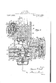
- Fig. 1 is a vertical, irregular, sectional view of the tri le valve, taken on the lines I-I of Fig. 3, t e section of the main slide valve and emergency valve being taken on the line II of Fig. 4;
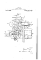
- Fig. 2 a section on line II-II of Figs. 1 and 4;
- Fig. 2 the same as Fig. 2, in emergency position;
- Fig. 2 a view similar to Fig. 2, showing the emergency slide valve in its second position;
- Fig. 3 an irregular, vertical, sectional view taken on the lines IIL- III of Figs. 1 and 4, the section of the automatic emergency valve being taken on the line III'*III of Fig 1;
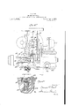
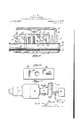
- Fig. 4 a plan view of the triple valve
- slide valve housings and slide valves being removed to show the valve seats and some of the orts and passages;
- Fig. 4 a similar view showing other ports and passages
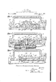
- Figs. 5, 5* and 5" sectional views of the main slide valve, the graduating valve and the valve seat, taken on the lines I-I, IIII and IIIIII of Fig. 11, showing the valves in brake pipe reservior charging position;
- Figs. 6, 6 and 6 are views similar to Figs. 5, 5 and 5", showing the valves in emergency reservoir charging position;
- Figs. 7, 7 a and 7" are views similar to Figs. 5, 5 and 5", showing the valves in service application position;
- Figs. 8, 8 and 8* are views similar to Figs. 5, 5 and 5", showing the valves in service lap osition;
- Figs. 9, 9 and 9 are views similar to Figs. 5, 5 and 5", showing the valves in emergency position;
- Fig. 10 a bottom plan view of graduating valve
- Fig. 11 a bottom plan view of main slide valve
- Fig. 12 a plan view of main slide valve seat
- Fig. 13 a vertical, sectional view of the release-governing valve on line XIIIXIII of Fig. 4 I
- Fig. 14 a detail bottom plan view of the release governing valve
- Fig. 15 a diagram of apparatus
- Fig. 16 a face view of the pilot valve supporting flan e
- Fig. 17 a face view of the pilot valve seat
- Fig. 18 a face view of the pilot valve
- Fig. 19 a vertical sectional view of the ilot valve in lap position on lines XX of Fi s. 16, 17 and 18;
- Fig. 21 a detail sectional view showing the check valve between the brake pipe reservoir and the quick-action chamber
- Fig. 22 a detail cross-sectional viewof the main slide valve, showing the ball check valve 147;
- Fig. 23 a detail view of the ball check valve cage removed from the slide valve.
- A designates the triple valve body; B the emergency reservoir; C the brake cylinder, and D a brake pipe reservoir (See Fig. 15.)
- the triple valve comprises a lower controller section E, which contains the means for controlling brake cylinder pressure; the main slide valve ,section F, which contains the service and emergency slide valves and the quick-release valve; and the emergency pilot valve section G, which is connected to the main section. (See Fig.- 3.)
- H designates the brake pipe; Ithe main or service slide valve; J the emergency slide valve; K the pilot valve controlling the triple valve for service applications of the brakes and the graduated release of the brakes; L the emergency pilot slide valve which controls the automatic emergency operation of the triple valve; and M the release-governing valve by means of which the triple may be adjusted for a graduated re lease of the brakes or a full, slow release of the brakes, or for a quick, full release of the brakes, and N the graduating valve.
- the main slide valve section of the triple valve body is formed with a main brake pipe chamber 2; a main slide valve chamber 3; a supplemental brake pipe chamber 4; and an emergency slide valve chamber 5, this later chamber being always in open communication with the main brake pipe chamber 2.
- a cylindrical chamber 6 in which is mounted to reciprocate a main actuating piston 7.
- a cylindrical chamber 8 in which is fitted to reciprocate an emergency piston 9, said piston forming one wall of a quick-action chamber 10, so that said'emergency piston will be subject on one side to brake pipe pressure, and on its other side to the pressure in the quick-action chamber.
- the brake pipe H is connected to the lower or controller section of the triple valve at H, and communicates directly with passages 11, 12 and 13, this latter passage ex tending around the supplemental brake pipe chamber and communicating with a port 14 in the main slide valve seat.
- Communicating with the passage 12 is a passage 15, which opens through a 'port 16, in the emergency valve seat, this latter port being in communication with the emergency slide valve chamber at all times through a port in the emergency slide valve, except when said valve is moved to emergency position, as will be fully hereinafter set forth.
- Brake pipe pressure will be registered in the main brake pipe chamber 2, and the emergency slide valve chamber 5, and the main actuating piston 7 and the emergency piston 9 will be subject to brake pipe pressure during all positions of the triple valve other than emergency.
- the emergency piston is larger in area than the main actuating piston. As shown in the drawings, the area is about twice that of the main actuating piston. This greater area is for a purpose which will fully hereinafter appear.
- the supplemental brake pipe chamber is fitted with a bushing 17, the upper surface of this bushing forming the main slide valve seat 18, through which the port 14 is formed.
- the main slide valve 1 On the seat 18 is mounted the main slide valve 1. On top of the main slide valve'is mounted the graduating valve N, this latter valve being held to its seat by a spring bearing thereon and retained in the usual housing in the slide valve chamber 3, (Fig. 2). The main slide valve is also held to its seat by a suitable spring.
- the main slide valve chamber 3 is closed by a'cap plate ing and serves to accurately guide the piston stem and the piston.
- the head 22 is provided with an upwardly extending post 23, which extends through a slot 24 in the main slide valve seat. and into a slot 25 in the main slide valve.
- the slot 24 is of suflicient length to permit of the full movement of the piston stem; and the slot 25 in the main slide valve is of sufiicient length to permit the piston to move the graduating valve a limited distance without moving the main slide valve.
- the post 23 is provided with an upwardly extending reduced portion 26, which engages a recess in the under side of the graduating valve. It is manifest that the graduating valve will be first moved by the actuating piston, and that when the lost motion is taken up in the slot 25, the post 23 will engage the main slide valve and thereafter the two valves will move together.
- the main actuating piston is also provided with a stem 27, which extends outwardly into. the brake pipe chamber 2, and carries at its free end a depending cross-head 28.
- the emergency piston 9 is provided with a central operating stem 29, the inner end of which extends into the emergency slide valve chamber.
- the emergency piston stem extends through an aperture in the lower end of the cross-head 28, and isformed on opposite sides of said cross-head with stops 30 and 31; the stop 30 is in the form of a collar, and the stop 31 is in the form of a head having an axial bore or'opening 32. (See Fig. 2.) There is a space between the two stops sufficient to permit of a limited independent movement of the connected parts, as will be more fully hereinafter described.
- the upper end of the cross-head 28 engages the inner end of a replacing plunger 33, which is normally maintained extended into the path-of the said cross-head by :1 replacing spring 34.
- One end of the replacing plunger is formed with a head 35, which is adapted to reciprocate in a cham' ber 36, the inner wall of said chamber formmg a stop for the plunger head to limit the movement of the plunger under the tension of the replacing spring.
- the emergency slide valve J i mounted between abutments formed on the emergency valve stem 37, and is held to its seat by a flat spring arranged between the said stem and the upper surface of said valve.
- One end of the emergency valve stem fits and slides in the axial bore 32 of the head 31, and there is suiiicient lost motion between these parts to permit the main actuating piston to move the main slide valve to service position without operating the emergency valve.
- the inner end of the" emergency valve stem is connected to a spring-pressed plunger 38, which normally holds the emergency slide valve in position on its seat and returns the said valve to normal position after an emergency application of the brakes when the pressures on opposite sides of the emergency piston have equalized, as will be more fully hereinafter described.
- the emergency valve seat is formed with a brake pipe exhaust port 39; and the emergency slide valve is formed with. a passage 40, which is adapted to lace the exhaust port in direct communication with the brake pipe port 16, to vent the brake pipe direct to atmosphere ⁇ for an emergency application of the brakes, and when the emergency slide valve is moved to emergency position.
- the emergency slide valve i also formed With a port 41, which at all times, except in the emergency position of the valve, is in direct communication with the brake pipe port 16, so that brake pipe pressure will be always registered in the emergency slide valve chamber 5 and the main brake pipe chamber 2. except as above stated.
- the controller section E of the triple valve comprises the main body, casting 42, which is formed with a flange at its upper end by means of which it i bolted to the under side ofthe main slide valve section F.
- the lower end of this casting 42 is provided with a horizontal circular flange to the under side of which is bolted a spacing ring 43, and to this spacing ring is bolted another spacing ring 44, and to the lower end of the section is bolted a cap plate 45.
- an actuating diaphragm 46 Between the flange on the lower end of the casting 42 and the spacing ring 43 is secured an actuating diaphragm 46, said diaphragm forming the lower wall of an actuating chamber 47, this chamber being in direct open communication with the main brake pipe chamber 2 through passage 48, so that brake pipe pressure will be always registered inthe actuating cham her and on the u per side oLthe actuating diaphragm 46.
- etween the spacing rings 43 and 44 is secured a controlling diaphragm 49, this diaphragm being larger in area than the actuating diaphragm 46.
- an emergency diaphragm 50 Between the lower side of the spacing ring 44 and the upper side of the cap plate 45 is secured an emergency diaphragm 50.
- a brake cylinder controlling chamber 51 which is in communication with the brake cylinder through the passage 52, a will be more fully hereinafter described.
- the chamber 53 between the controlling diaphragm and the emergency diaphragm is vented to atmosphere through passage 53 at all times, (see Fig. 3,) except when the valve is in emergency position, as will be fully herein set forth.
- Chamber 54 below the emergency diaphragm is in communication with the emergency reservoir through passage 55, so that emergency reservoir pressure will be always registered in said chamber, as will fully hereinafter apear.
- the head of the actuating diaphragm 46 is formed with a'central upwardly extending stem 56, which extends through the actuat ing chamber, its upper end being guided in a. socket formed in the upper wall of said chamber.
- This stem is slotted transversely and through said slot extends a substantially horizontal operating lever 57, a pair of pins 58 connecting said lever to the stem.
- the left-hand end of the lever 57 is pivoted on a fulcrum block mounted in the actuating chamber; the right-hand end of said lever extending through a suitable slot in the controller section and into the casing of the pilot valve K, said lever being of sutlicient length to provide an adequate movement of the pilot valve with a very slight movement of the actuatin diaphragm.
- the pilot slide valve Ix is moved in response to variations in pressure in the brake pipe and controls the charging of the brake ipe reservoir and emergency reservoir; serv- 1ce applications of the brake; the
- This valve comprises a plate 59, on the outer face of which is formed the pilot valve seat 60; and to said plate is secured a housing 61, this latter forming pilot valve chamber 62.
- the pilot slide valve K reciprocates vertically on valve seat 60, and is mounted between abutments or shoulders formed on the pilot valve stem 64, and is held to this seat by a flat spring, as shown clearly in Fig. 3.
- the righthand end of the lever 57 is connected to the stem 64, so that the pilot valve will be moved by said lever in response to the movements of the'diaphragms 46, 49 and 50.
- the upper end of the valve stem is guided in a rigid block; and the lower end thereof slides in a vertically arranged sleeve 65, said sleeve being adapted to reciprocate vertically in a stud 63 formed on the valve plate 59.
- the sleeve 65 is provided on its upper end with screw collars which are adapted to be engaged by the shouldered valve stem; and the lower end of said sleeve is provided with a collar 66, which is adapted to engage the rigid stud 63 on the valve plate to limit the upward movement of said sleeve.
- a spring 67 is interposed between the rigid stud of the valve plate and the collars on the upper end of the sleeve. and normally holds the stop collar 66 against the rigid stud 63.
- the sleeve is slidable in the stud 63, and the valve stem is independently slidable in the sleeve for purposes which will fully hereafter appear.
- the pilot valve and its seat are provided with ports and passages by means of which its various functions are secured, and these ports and passages will be fully described when describing in detail each operation of the valve.
- an adjustable stop 68 to limit the downwardmovement of the diaphragins.
- the upward movement of the diaphragms is limited by the upper end of the stem 56, engagin the bottom of the guiding socket formed in the upper wall of the actuating chamber.
- the release governing valve M (Figs. 1, 13 and 14) which controls the graduated release or the quick release of the brakes is mounted to slide on a horizontal valve seat 69 formed on the top of the main slide valve section F, the release valve chamber 70 being formed by a housing 71.
- the release valve is connected to a post 72, which extends upwardly through a slot 72*, from a reciprocatable rod 73, mounted in a suitable housing in the mainvalve section, and provided at one end with coupling lugs 74, to which a suitable operating rod may be secured.
- This valve is designed to be shifted manually into its quick-release or graduated'release position. lVhen the valve is in position to secure a quick release of the brakes, it is shifted to the position shown in Fig.
- the automatic emergency pilot valve provides means whereby when the brake pipepressure, and of course the brake pipe reservoir pressure which is in direct communication with the brake pipe, is abnormally reduced by slow reductions, the triple valve will be moved to emergency position to bring about an emergency application of the brakes.
- This valve comprlses a valve-casing 75, adapted to be secured to a vertical face of the main slide valve section, said casing forming a chamber 76 near its lower end, which is in communication through port 77 and connected passage 78, with a port 139 in the main slide valve seat,
- a piston casing 79 in which is mounted a piston 80, said' piston being held in its normal, lower position by means of a compression spring 81, said spring being arranged in a chamber 82 above the piston, as shown clearly in Fig.
- the chamber 82 is connected through port 83 and the connected passages with a port 99 in the main slide valve seat.
- the chamber 7 9 below the piston 80 is connected by port 84 and passages 89 to the quick-action chamber 10 and through a passage 90 to a port 91 in the seat of-the emergency slide valve, (Figs. 4: and 2) so that brake pipe reservoir pressure and the quick-action chamber pressure will be always registered in said chamber 79.
- a valve L slides on a seat formed on the outer side of the main piston casing 79', and said valve is connected to the piston 80 by a stem 85.
- the emergency pilot slide valve L is formed with a port 86, which normally communicates through a suitable passage with the interior of the chamber 79.
- the said pilot valve is mounted in a valve chamber 87, which chamber is in open communication with the chamber 76 formed at the bottom of the valve chamber, this latter chamber being in communication with the port 77.
Landscapes
- Engineering & Computer Science (AREA)
- Transportation (AREA)
- Mechanical Engineering (AREA)
- Valves And Accessory Devices For Braking Systems (AREA)
Description
S. G. NEAL.
AIR BRAKE APPARATUS.
APPLICATION FILED NOV-13,1918- RENEWED AUG-30,1921.
1,41 1,368. Patented Apr. 4, 1922.
15 SHEETS-SHEET W f 5 wuamtoz g 2 I .1
S. G. NEAL.
AIR BRAKE APPARATUS.
APPLICATION FILED NOV. I3. 1918. RENEWED AUG-30.1921.
1,41 1,368. Patented Apr. 4, 1922.
15 SHEETS-SHEET 2- afww. 951, Q
S. G. NEAL.
AIR BRAKE APPARATUS.
APPLICATION FILED NOV. 1a, 1918. RENEWED AUfi. so, 1921. 1 411 860 Patented Apr. 4, 1922.
15 $HEETSSHEET 3- s. G. NEAL.
AIR BRAKE APPARATUS. APPLICATION FILED NOV. 13, 1918. RENEW ED AUG. 30,1921. L H 1 8680 Patented Apr. 4 1922a 15 SHEETS-SHEET L.
INVENTOR ATTORNEYfl S. G. NEAL.
AIR BRAKE APPARATUS.
APPLICATION FILED NOV. 13, 1918.. RENEWED AUG-30,1921.
1,41 1 86. Pawnted Apr. 4, 1922.
15 SHEETS-SHEET 5- S. G. NEAL.
AIR BRAKE APPARATUS.
APPLICATION FILED NOV. 13. 1918i RENEWED AUG. 30. 1921.
1,41 1,368. Patented Apr. 4, 1922.
15 $HEETSSHEET 6- (qwuewtoz at K0191421 1;
Patented Apr. 41 1922.
15 SHEETS-SHEET 7.
'arto'cmuga S. G. NEAL.
AIR BRAKE APPARATUS.
APPLICATION man NOV. 13. 191B. RENEWED AUG. 30. 1921.
1,411,368. Patented Apr. 4, 1922.
15 SHEETSSHEET 8- F #p f W @L 1% I A m I J W 4%? w A? 27 AW fif \//J 2 MUM/8% S. G NEAL.
AIR BRAKE APPARATUS.
APPLICATION FILED NOV. 13, 1918. RENEWED AUG. 30. 1921.
Patented Apr. 4, 1922.
[5 SHEETSSHEET 9.
j J l V W? v A \m k Elmfiaavcr Ewe-Ava? 69/4196746 far/no Shag S. G. NEAL.
AIR BRAKE APPARATUS.
APPLICATION FILED NOV. 13, 1918. RENEWED AUG. 30, 1921.
I5 SHEETS-SHEET 10.
k. W z
6271/66 APP; 1047/04 65/7/04 @q 4 arr 0114 12134 avwewfoz s. e. NEAL. AIR BRAKE APPARATUS.
APPLICATION FILED NOV. I3, 1918. RENEWED AUG. 30, 1921.
I5 SHEETS-SHEET II.
1' {I} Q /59 w //7 mg m 9.9 I 52 /27 W4 7/ "Z 2: I I I I I \\\m\\\\\\\ m m WWW/ ismwcz ZAP Raw/770m 6] muewfoz KW V/ S. G. NEAL.
AIR BRAKE APPARATUS..
APPLICATION FILED NOV. 13, 1918. RENEWED AUG. 30, 1921.
1 41 1,368, Patented. Apr. 4,1922.
15 $HEETSSHEET 12.
g vwawfoz M/SLW S. G. NEAL.
AIR BRAKE APPARATUS. APPLICATION FILED NOV. I3, 1918- RENEWED AUG. 30, 1921.
31,41 1 fi6 Patented Apr. 4 1922.
15 SHEETSSHEET I4.
AIR BRAKE APPARATUS.
APPLICATION FILED NOV. 13. 1918. RENEWED AUG. 30. 1921.
Patented Apr. 4, 1922.
15 SHEETS-SHEET 5.
UNITED STATES PATENT OFFICE.
SPENCER GEARY NEAL, OF NEW YORK, N. Y., ASSIGNOR TO AUTOMATIC STRAIGHT AIR BRAKE COMPANY, OF WILMINGTON, DELAWARE, A CORPORATION OF DELA- WARE.
AIR-BRAKE APPARATUS.
Specification of Letters Patent.
- Patented Apr. 4, 1922.
Application filed November 13, 1918, Serial No. 262,298. Renewed August 30, 1921. Serial No. 497,045.
To all whom it may concern:
Be it known that I, SPENCER G. NEAL, a citizen of the United States, and resident of the borough of Manhattan, city, county, and State of New York, have invented certain new and useful Improvements in Air-Brake Apparatus, (Case # 36,) of which the following is a specification.
This invention relates to improvements in that type of air brake apparatus disclosed in Patent No. 1,082,758 dated December 30, 1913, and in Patent No. 1,183,103, dated May 16, 1916, wherein brake pipe air is used for all service applications of the brakes, an emergency reservoir supplying air for emergency applications of the brakes. In the apparatus disclosed in said patents the brake pipe volume is augmented by a brake pipe reservoir which is in open communication with the brake pipe during all service applications of the brakes, and supplies the neoessary,volume of air for service braking. It is a further characteristic of the apparatus disclosed in the patents mentioned that the brake cylinder pressure controls the movement of the triple valve to lap position, the triple valve operating in all applications of the brakes to admit air to the brake cylinder until a pressure is built up therein having a predetermined ratio to the amount of train pipe reduction, and this regardless of brake cylinder leaks and varying piston travel.
Patent No. 1,183,103, dated May 16, 1916, shows a means whereby the emergency reservoir air may be discharged intg' the train pipe upon an increase of train pipe pressure to thereby quickly raise the brake pipe pressure for a quick release of the brakes. I
The apparatus disclosed in this application has all of the essential functions of the apparatus disclosed in the two patents mentioned herein, and in addition possesses many broadly new principles of operation and features of construction, all of which will be fully pointed out hereinafter.
One of the main objects of this invention is to provide a triple valve having a main actuating piston subject on both sides to brake pipe pressure, means being provided whereby a reduction in brake pipe pressure will exhaust the brake pipe air from one side of said actuating piston, and permit the brake pipe air on the opposite side thereof to exert its full power to move said piston and the main slide valve connected thereto to application position.
Another object of the invention is to provide in a triple valve an actuating piston subject on both sides to brake pipe air, a pilot or controlling valve operating upon a reduction of brake pipe pressure for an application of the brakes to exhaust the brake the brake pipe air from one side of the actuating piston, to thereby permit substantially the full power of the brake pipe air on the opposite side of the piston to move the main actuating piston and the slide valve connected thereto to application position.
Another object of the invention is to provide means whereby when the actuating piston and the main slide valve have been moved to service application position brake and a main slide valve connected thereto,
the piston being held normally between balanced air pressures and means being pro vided whereby a reduction of brake pipe pressure will-cause the substantial exhaust of the. air from one side of the actuating piston, thereby permitting the air on the other side thereof to act substantially unopposed and to exert its full power on the actuating piston to move it and its slidevalve to service position.
Another object of the invention is to provide means whereby the brake cylinder pres sure will control the return of the graduating slidevalve from application position to lap position.
A further object of the invention is to provide means whereby the brake cylinder pressure will control means for equalizing the brake pipe pressure on opposite sides of the main actuating piston, and thereby control the movement of the graduating slide valve from application position to lap pos ition.
Another ob'ect of the invention is to provide means w ereby should the brake cylinder pressure leak down below a predetermined pressure, air from one side of the actuating piston will be exhausted, thereby permitting brake pipe air to move the main slide valve to service position to build up brake cylinder pressure sufficiently to compensate for the leak, said main slide valve being moved back to lap position when the desired brake cylinder pressure is again reached.
Another objectof the invention is to provide an automatic mergency pilot valve which will operate when the brake pipe pressure has been reduced to or below a certain degree to bring about an emergency operation of the triple valve.
Another object of the invention is to provide means whereby upon an increase in brake pipe pressure for a release of the brakes the emergency reservoir air will be admitted to one side of the main actuating piston to move said piston and the connected slide valve to full release position in opposition to the increased brake pipe pressure on the other side of the actuating piston.
In the drawings, Fig. 1 is a vertical, irregular, sectional view of the tri le valve, taken on the lines I-I of Fig. 3, t e section of the main slide valve and emergency valve being taken on the line II of Fig. 4;
Fig. 2 a section on line II-II of Figs. 1 and 4;
Fig. 2 the same as Fig. 2, in emergency position;
Fig. 2" a view similar to Fig. 2, showing the emergency slide valve in its second position;
Fig. 3 an irregular, vertical, sectional view taken on the lines IIL- III of Figs. 1 and 4, the section of the automatic emergency valve being taken on the line III'*III of Fig 1;
Fig. 4 a plan view of the triple valve, the
slide valve housings and slide valves being removed to show the valve seats and some of the orts and passages;
. Fig. 4 a similar view showing other ports and passages;
Figs. 5, 5* and 5" sectional views of the main slide valve, the graduating valve and the valve seat, taken on the lines I-I, IIII and IIIIII of Fig. 11, showing the valves in brake pipe reservior charging position;
Figs. 6, 6 and 6 are views similar to Figs. 5, 5 and 5", showing the valves in emergency reservoir charging position;
Figs. 7, 7 a and 7" are views similar to Figs. 5, 5 and 5", showing the valves in service application position;
Figs. 8, 8 and 8* are views similar to Figs. 5, 5 and 5", showing the valves in service lap osition;
Figs. 9, 9 and 9 are views similar to Figs. 5, 5 and 5", showing the valves in emergency position;
Fig. 10 a bottom plan view of graduating valve;
Fig. 11 a bottom plan view of main slide valve;
Fig. 12 a plan view of main slide valve seat;
Fig. 13 a vertical, sectional view of the release-governing valve on line XIIIXIII of Fig. 4 I
Fig. 14 a detail bottom plan view of the release governing valve;
Fig. 15 a diagram of apparatus;
Fig. 16 a face view of the pilot valve supporting flan e;
Fig. 17 a face view of the pilot valve seat;
Fig. 18 a face view of the pilot valve;
Fig. 19 a vertical sectional view of the ilot valve in lap position on lines XX of Fi s. 16, 17 and 18;
ig. 20 a view similar to Fig.'19, in service position; I
Fig. 21 a detail sectional view showing the check valve between the brake pipe reservoir and the quick-action chamber;
Fig. 22 a detail cross-sectional viewof the main slide valve, showing the ball check valve 147; and
Fig. 23 a detail view of the ball check valve cage removed from the slide valve.
Referring to the various parts by reten ence characters, A designates the triple valve body; B the emergency reservoir; C the brake cylinder, and D a brake pipe reservoir (See Fig. 15.)
The triple valve comprises a lower controller section E, which contains the means for controlling brake cylinder pressure; the main slide valve ,section F, which contains the service and emergency slide valves and the quick-release valve; and the emergency pilot valve section G, which is connected to the main section. (See Fig.- 3.)
H designates the brake pipe; Ithe main or service slide valve; J the emergency slide valve; K the pilot valve controlling the triple valve for service applications of the brakes and the graduated release of the brakes; L the emergency pilot slide valve which controls the automatic emergency operation of the triple valve; and M the release-governing valve by means of which the triple may be adjusted for a graduated re lease of the brakes or a full, slow release of the brakes, or for a quick, full release of the brakes, and N the graduating valve.
In order to simplify the description, the
parts of the apparatus and their functions, and the various ports, passages and valves will be described in detail in connection with the several valve operations.
The main slide valve section of the triple valve body is formed with a main brake pipe chamber 2; a main slide valve chamber 3; a supplemental brake pipe chamber 4; and an emergency slide valve chamber 5, this later chamber being always in open communication with the main brake pipe chamber 2. Intermediate between the main brake pipe chamber 2 and the supplemental brake pipe chamber 4 is formed a cylindrical chamber 6, in which is mounted to reciprocate a main actuating piston 7. Also formed in the main brake pipe chamber, axially in line with the emergency slide valve chamber 5 is a cylindrical chamber 8, in which is fitted to reciprocate an emergency piston 9, said piston forming one wall of a quick-action chamber 10, so that said'emergency piston will be subject on one side to brake pipe pressure, and on its other side to the pressure in the quick-action chamber.
The brake pipe H is connected to the lower or controller section of the triple valve at H, and communicates directly with passages 11, 12 and 13, this latter passage ex tending around the supplemental brake pipe chamber and communicating with a port 14 in the main slide valve seat. Communicating with the passage 12 is a passage 15, which opens through a 'port 16, in the emergency valve seat, this latter port being in communication with the emergency slide valve chamber at all times through a port in the emergency slide valve, except when said valve is moved to emergency position, as will be fully hereinafter set forth. Brake pipe pressure will be registered in the main brake pipe chamber 2, and the emergency slide valve chamber 5, and the main actuating piston 7 and the emergency piston 9 will be subject to brake pipe pressure during all positions of the triple valve other than emergency.
The emergency piston is larger in area than the main actuating piston. As shown in the drawings, the area is about twice that of the main actuating piston. This greater area is for a purpose which will fully hereinafter appear. The supplemental brake pipe chamber is fitted with a bushing 17, the upper surface of this bushing forming the main slide valve seat 18, through which the port 14 is formed.
On the seat 18 is mounted the main slide valve 1. On top of the main slide valve'is mounted the graduating valve N, this latter valve being held to its seat by a spring bearing thereon and retained in the usual housing in the slide valve chamber 3, (Fig. 2). The main slide valve is also held to its seat by a suitable spring. The main slide valve chamber 3 is closed by a'cap plate ing and serves to accurately guide the piston stem and the piston. The head 22 is provided with an upwardly extending post 23, which extends through a slot 24 in the main slide valve seat. and into a slot 25 in the main slide valve. The slot 24 is of suflicient length to permit of the full movement of the piston stem; and the slot 25 in the main slide valve is of sufiicient length to permit the piston to move the graduating valve a limited distance without moving the main slide valve. The post 23 is provided with an upwardly extending reduced portion 26, which engages a recess in the under side of the graduating valve. It is manifest that the graduating valve will be first moved by the actuating piston, and that when the lost motion is taken up in the slot 25, the post 23 will engage the main slide valve and thereafter the two valves will move together.
The main actuating piston is also provided with a stem 27, which extends outwardly into. the brake pipe chamber 2, and carries at its free end a depending cross-head 28. The emergency piston 9 is provided with a central operating stem 29, the inner end of which extends into the emergency slide valve chamber. The emergency piston stem extends through an aperture in the lower end of the cross-head 28, and isformed on opposite sides of said cross-head with stops 30 and 31; the stop 30 is in the form of a collar, and the stop 31 is in the form of a head having an axial bore or'opening 32. (See Fig. 2.) There is a space between the two stops sufficient to permit of a limited independent movement of the connected parts, as will be more fully hereinafter described. The upper end of the cross-head 28 engages the inner end of a replacing plunger 33, which is normally maintained extended into the path-of the said cross-head by :1 replacing spring 34. One end of the replacing plunger is formed with a head 35, which is adapted to reciprocate in a cham' ber 36, the inner wall of said chamber formmg a stop for the plunger head to limit the movement of the plunger under the tension of the replacing spring. When the replacing spring is compressedthrough the action of the main actuating piston and the crosswill engage the outer Wall of the chamber 36 and thereafter the plunger will form a rigid stop for the main actuating piston.
The emergency slide valve J i mounted between abutments formed on the emergency valve stem 37, and is held to its seat by a flat spring arranged between the said stem and the upper surface of said valve. One end of the emergency valve stem fits and slides in the axial bore 32 of the head 31, and there is suiiicient lost motion between these parts to permit the main actuating piston to move the main slide valve to service position without operating the emergency valve. The inner end of the" emergency valve stem is connected to a spring-pressed plunger 38, which normally holds the emergency slide valve in position on its seat and returns the said valve to normal position after an emergency application of the brakes when the pressures on opposite sides of the emergency piston have equalized, as will be more fully hereinafter described. The emergency valve seat is formed with a brake pipe exhaust port 39; and the emergency slide valve is formed with. a passage 40, which is adapted to lace the exhaust port in direct communication with the brake pipe port 16, to vent the brake pipe direct to atmosphere\ for an emergency application of the brakes, and when the emergency slide valve is moved to emergency position. The emergency slide valve i also formed With a port 41, which at all times, except in the emergency position of the valve, is in direct communication with the brake pipe port 16, so that brake pipe pressure will be always registered in the emergency slide valve chamber 5 and the main brake pipe chamber 2. except as above stated.
The controller section E of the triple valve comprises the main body, casting 42, which is formed with a flange at its upper end by means of which it i bolted to the under side ofthe main slide valve section F. The lower end of this casting 42 is provided with a horizontal circular flange to the under side of which is bolted a spacing ring 43, and to this spacing ring is bolted another spacing ring 44, and to the lower end of the section is bolted a cap plate 45. Between the flange on the lower end of the casting 42 and the spacing ring 43 is secured an actuating diaphragm 46, said diaphragm forming the lower wall of an actuating chamber 47, this chamber being in direct open communication with the main brake pipe chamber 2 through passage 48, so that brake pipe pressure will be always registered inthe actuating cham her and on the u per side oLthe actuating diaphragm 46. etween the spacing rings 43 and 44 is secured a controlling diaphragm 49, this diaphragm being larger in area than the actuating diaphragm 46. Between the lower side of the spacing ring 44 and the upper side of the cap plate 45 is secured an emergency diaphragm 50. All of these diaphragms are provided with independent central rigid heads which bear against each other at all times, so that the three diaphragms always move together. Between the actuating diaphragm aiid the controlling diaphragm is formed a brake cylinder controlling chamber 51, which is in communication with the brake cylinder through the passage 52, a will be more fully hereinafter described. The chamber 53 between the controlling diaphragm and the emergency diaphragm is vented to atmosphere through passage 53 at all times, (see Fig. 3,) except when the valve is in emergency position, as will be fully herein set forth. Chamber 54 below the emergency diaphragm is in communication with the emergency reservoir through passage 55, so that emergency reservoir pressure will be always registered in said chamber, as will fully hereinafter apear.
The head of the actuating diaphragm 46 is formed with a'central upwardly extending stem 56, which extends through the actuat ing chamber, its upper end being guided in a. socket formed in the upper wall of said chamber. This stem is slotted transversely and through said slot extends a substantially horizontal operating lever 57, a pair of pins 58 connecting said lever to the stem. The left-hand end of the lever 57 is pivoted on a fulcrum block mounted in the actuating chamber; the right-hand end of said lever extending through a suitable slot in the controller section and into the casing of the pilot valve K, said lever being of sutlicient length to provide an adequate movement of the pilot valve with a very slight movement of the actuatin diaphragm. I
The pilot slide valve Ix is moved in response to variations in pressure in the brake pipe and controls the charging of the brake ipe reservoir and emergency reservoir; serv- 1ce applications of the brake; the
graduated release of the brakes; the grac uated application of the brakes; the slow, full release of the brakes, and the quick, full release of the brakes. This valve comprises a plate 59, on the outer face of which is formed the pilot valve seat 60; and to said plate is secured a housing 61, this latter forming pilot valve chamber 62. The pilot slide valve K reciprocates vertically on valve seat 60, and is mounted between abutments or shoulders formed on the pilot valve stem 64, and is held to this seat by a flat spring, as shown clearly in Fig. 3. The righthand end of the lever 57 is connected to the stem 64, so that the pilot valve will be moved by said lever in response to the movements of the'diaphragms 46, 49 and 50. The upper end of the valve stem is guided in a rigid block; and the lower end thereof slides in a vertically arranged sleeve 65, said sleeve being adapted to reciprocate vertically in a stud 63 formed on the valve plate 59. The sleeve 65 is provided on its upper end with screw collars which are adapted to be engaged by the shouldered valve stem; and the lower end of said sleeve is provided with a collar 66, which is adapted to engage the rigid stud 63 on the valve plate to limit the upward movement of said sleeve. A spring 67 is interposed between the rigid stud of the valve plate and the collars on the upper end of the sleeve. and normally holds the stop collar 66 against the rigid stud 63. The sleeve is slidable in the stud 63, and the valve stem is independently slidable in the sleeve for purposes which will fully hereafter appear.
The pilot valve and its seat are provided with ports and passages by means of which its various functions are secured, and these ports and passages will be fully described when describing in detail each operation of the valve.
Through the cap plate 45 (see Fig. 3) is screwed an adjustable stop 68 to limit the downwardmovement of the diaphragins. The upward movement of the diaphragms is limited by the upper end of the stem 56, engagin the bottom of the guiding socket formed in the upper wall of the actuating chamber.
The release governing valve M, (Figs. 1, 13 and 14) which controls the graduated release or the quick release of the brakes is mounted to slide on a horizontal valve seat 69 formed on the top of the main slide valve section F, the release valve chamber 70 being formed by a housing 71. The release valve is connected to a post 72, which extends upwardly through a slot 72*, from a reciprocatable rod 73, mounted in a suitable housing in the mainvalve section, and provided at one end with coupling lugs 74, to which a suitable operating rod may be secured. This valve is designed to be shifted manually into its quick-release or graduated'release position. lVhen the valve is in position to secure a quick release of the brakes, it is shifted to the position shown in Fig. 13, and then places the emergency reservoir in communication with the brake pipe through passage 110, groove 111 and port and passage 95 when the main slide valve is moved to release position by an increase of. brake pipe pressure. When the release-governing valve is shifted to its graduated-release position this communication between the emergency reservoir and the brake pipe is closed. and the groove 137 is disconnected from ports 136' and 188, and the release of the brakes will take place wholly through the pilot valve. The ports and passages connected with the release valve will be "fully described in connection with they quick-release operation of the brake cylinder for service applications of the brakes, it is desirable to provide means to automatically bring about an emergency application of the brakes, should the brake pipe pressure be so reduced as to afford insuflicient braking power for the safe control of the train. The automatic emergency pilot valve provides means whereby when the brake pipepressure, and of course the brake pipe reservoir pressure which is in direct communication with the brake pipe, is abnormally reduced by slow reductions, the triple valve will be moved to emergency position to bring about an emergency application of the brakes. This valve comprlses a valve-casing 75, adapted to be secured to a vertical face of the main slide valve section, said casing forming a chamber 76 near its lower end, which is in communication through port 77 and connected passage 78, with a port 139 in the main slide valve seat, In the valve casing '75 is arranged a piston casing 79, in which is mounted a piston 80, said' piston being held in its normal, lower position by means of a compression spring 81, said spring being arranged in a chamber 82 above the piston, as shown clearly in Fig. 3. The chamber 82 is connected through port 83 and the connected passages with a port 99 in the main slide valve seat. The chamber 7 9 below the piston 80is connected by port 84 and passages 89 to the quick-action chamber 10 and through a passage 90 to a port 91 in the seat of-the emergency slide valve, (Figs. 4: and 2) so that brake pipe reservoir pressure and the quick-action chamber pressure will be always registered in said chamber 79. A valve L slides on a seat formed on the outer side of the main piston casing 79', and said valve is connected to the piston 80 by a stem 85. The emergency pilot slide valve L is formed with a port 86, which normally communicates through a suitable passage with the interior of the chamber 79. The said pilot valve is mounted in a valve chamber 87, which chamber is in open communication with the chamber 76 formed at the bottom of the valve chamber, this latter chamber being in communication with the port 77. When the brake pipe pressure is reduced abnormally the pressure in the chamber 79 will be sui ficiently reduced to permit the spring 81 to lower the piston 80 and the connected valve L to the position shown in Fig. 3, thereby placing the chamber 76 in communication
Priority Applications (1)
| Application Number | Priority Date | Filing Date | Title |
|---|---|---|---|
| US262298A US1411368A (en) | 1918-11-13 | 1918-11-13 | Air-brake apparatus |
Applications Claiming Priority (1)
| Application Number | Priority Date | Filing Date | Title |
|---|---|---|---|
| US262298A US1411368A (en) | 1918-11-13 | 1918-11-13 | Air-brake apparatus |
Publications (1)
| Publication Number | Publication Date |
|---|---|
| US1411368A true US1411368A (en) | 1922-04-04 |
Family
ID=22996950
Family Applications (1)
| Application Number | Title | Priority Date | Filing Date |
|---|---|---|---|
| US262298A Expired - Lifetime US1411368A (en) | 1918-11-13 | 1918-11-13 | Air-brake apparatus |
Country Status (1)
| Country | Link |
|---|---|
| US (1) | US1411368A (en) |
-
1918
- 1918-11-13 US US262298A patent/US1411368A/en not_active Expired - Lifetime
Similar Documents
| Publication | Publication Date | Title |
|---|---|---|
| US1411368A (en) | Air-brake apparatus | |
| US1879643A (en) | Quick release device | |
| US3502374A (en) | Brake cylinder release valve | |
| US1487692A (en) | Fluid-pressure brake | |
| US2408123A (en) | Variable load brake | |
| US1078303A (en) | Triple valve for air-brakes. | |
| US1895479A (en) | Fluid pressure brake | |
| US1816078A (en) | Fluid pressure brake | |
| US1502519A (en) | Air-brake apparatus | |
| US2035046A (en) | Fluid pressure brake | |
| US1797411A (en) | Fluid-pressure brake | |
| US2088167A (en) | Fluid pressure brake | |
| US1780321A (en) | Triple-valve device | |
| US890823A (en) | Triple valve for graduating release. | |
| US1601587A (en) | Maurice | |
| US1418961A (en) | Air-brake apparatus | |
| US1012695A (en) | Triple valve for air-brakes. | |
| US1082758A (en) | Triple valve for air-brakes. | |
| US941914A (en) | Fluid-pressure-brake apparatus. | |
| US892122A (en) | Fluid-pressure brake-mechanism. | |
| US446386A (en) | William r | |
| US869637A (en) | Sensitive triple valve. | |
| US802285A (en) | Fluid-pressure brake. | |
| US2068318A (en) | Fluid pressure brake | |
| US831864A (en) | Retaining and recharging valve for air-brakes. |