US1854711A - Truck body - Google Patents
Truck body Download PDFInfo
- Publication number
- US1854711A US1854711A US460367A US46036730A US1854711A US 1854711 A US1854711 A US 1854711A US 460367 A US460367 A US 460367A US 46036730 A US46036730 A US 46036730A US 1854711 A US1854711 A US 1854711A
- Authority
- US
- United States
- Prior art keywords
- containers
- truck
- sockets
- retaining
- aisle
- Prior art date
- Legal status (The legal status is an assumption and is not a legal conclusion. Google has not performed a legal analysis and makes no representation as to the accuracy of the status listed.)
- Expired - Lifetime
Links
- 239000007789 gas Substances 0.000 description 5
- 210000005069 ears Anatomy 0.000 description 3
- 210000002105 tongue Anatomy 0.000 description 3
- 239000000463 material Substances 0.000 description 2
- 241000575946 Ione Species 0.000 description 1
- LTXREWYXXSTFRX-QGZVFWFLSA-N Linagliptin Chemical compound N=1C=2N(C)C(=O)N(CC=3N=C4C=CC=CC4=C(C)N=3)C(=O)C=2N(CC#CC)C=1N1CCC[C@@H](N)C1 LTXREWYXXSTFRX-QGZVFWFLSA-N 0.000 description 1
- 241000838698 Togo Species 0.000 description 1
- 238000010276 construction Methods 0.000 description 1
- 238000006073 displacement reaction Methods 0.000 description 1
- 238000005192 partition Methods 0.000 description 1
- 238000009877 rendering Methods 0.000 description 1
- 230000000717 retained effect Effects 0.000 description 1
- 238000000926 separation method Methods 0.000 description 1
Images

Classifications
-
- B—PERFORMING OPERATIONS; TRANSPORTING
- B60—VEHICLES IN GENERAL
- B60P—VEHICLES ADAPTED FOR LOAD TRANSPORTATION OR TO TRANSPORT, TO CARRY, OR TO COMPRISE SPECIAL LOADS OR OBJECTS
- B60P3/00—Vehicles adapted to transport, to carry or to comprise special loads or objects
- B60P3/055—Vehicles adapted to transport, to carry or to comprise special loads or objects for transporting bottles
Definitions
- Vto truck bod ies for use vin transporting 'cylindrical containers, particularly cylinders such ,as vafre employed for carrying compressed gases.
- Cylinders #containing Acompressed gases are usually fitted with :safety VValves, but the V'ailvessometimes fai-1, :and in that ⁇ case an enh cess of pressure can be built up, due, for instance, to the heat fof the outside atmosphere.
- the main yobject of any .inver-lation -is to v provide 'a ltruck body by means of which the containers are )retained vin position in such a manner that they are not subjected to severe impacts during transit, feither by :striking vagainst .each ⁇ other or against pamts -o fthe vehicle, and intov or'out of which the containers can nevertheless 'be .loaded for unload-ed easily and conveniently.
- the body includes :a floor 1Q., a transverse front mail 1.1 and three longitudinallyextending walls 12, two of which constitute the sides of thetruck body andthe .other oi' which constitutes .an intermediate partition.
- each aisle il iprovi'de a .retaining ycross. han' 1'6. having at its ends up- Warmllyv extending brackets 1.7 formed with tongues .11'8 projedting outwardly therefrom.
- Each fcross fbarr is lof such v'dimens-ions (depending uaponfthe Width ofthe :aisle which it s to housed) that the tonguestS' will enter the ,slots 111% 'of the sockets.
- yonfeasch side olf the aisle, the retaining har being thereby secured in position.
- the containers 13 may be stacked on end in rows in the truck, and the retaining bars then placed in position to hold in place the rearmost rows in the aisles. rIhus the containers are secured in position in such a manner that they cannot fall with any force against each other or against any part of the truck. Nevertheless the containers 'may be unloaded very conveniently, all that is necessary being that the retaining bar 16 at one end of an aisle be removed and replaced farther forward in the aisle after the containers have been unloaded.
- the rows of sockets 14 extend the whole length of the walls 12, as when the aisles have become partly emptied, the contents thereof can be shifted as a whole towards the rear of the truck, being then maintained in position by retaining bars engaging the front row like those engaging the rear row.
- each dummy comprises a ring 22 of a diameter corresponding with that of the containers 18, such ring being provided with a handle portion 23 and a hook portion 24 which is spaced away from the side of the ring 23 by a distance corresponding to the thickness of an upwardly extending web 25 with which the retaining bar 16 is provided.
- a dummy can be mounted in position on the retaining bar 16 by hooking the hook portion 24 thereof over the web 25 of the'retaining bar, such web then being enclosed between the hook portion 24 and the ring 22.
- the dummies are very easily placed in position and removed, and as many of them may be used as there'are vacancies in the last row of the containers.
- Figs. 4 there is shown an arrangement in which the walls 12 are provided with gates 26 intermediate their ends, permitting loading or unloading at the sides of the truck as well as at the rear end.
- retaining bars might be employed to close the portions of the aisles in front of the gates 26 and other retaining bars employed to close both ends of the aisles at the rear of the gates 26.
- FIG. 5 shows an arrangement similar to Fig. 4 but in which no intermediate wall 12 is employed, the truck not being divided into aisles.
- Fig. 6 is illustrated an arrangement in which a transverse wall 27 1s arranged at a suitable Vdistance behind the front end wall 11 of the truck body so as to provide a transverse aisle which is closed by a side gate 28, the retaining bars being, of course, disposed transversely of this aisle.
- the back portion of the truck body is divided into two aisles like those described above in connection with Figs. 1 to 3.
- a truck body for transporting cylindrical containers of uniform diameter
- the combination with a pair of members for confining a plurality of said containers in rows between them, a series of sockets mounted on each of said members, the individual sockets of each series being spaced apart by a distance substantially equal to the diameter of a container, and a retaining bar for engagement with an end row of said containers and adapted to be inserted between said members to enter one or another pair of said sockets in accordance with the position of the end row of containers; of a dummy of a width substantially equal to the diameter of said containers, said dummy having a hook for detachably mounting it upon said retain-V ing bar.
- a truck body for transporting cylindrical containers of uniform diameter the combination with a pair of members for conining a plurality of said containers in rows between them, a series of sockets mounted on each of said members, the individual sockets of each series being spaced apart by a distance substantially equal to the diameter of a container, and a retaining bar for engagement with an end row of said containers and adapted to be inserted between said members to enter one or another pair of said sockets in accordance with the position of the end row of containers, said retaining bar being provided with an upwardly extending web; of a dummy detaohably connected with said retaining bar and comprising a ring of a diameter substantially the same as that of said containers and a hook spaced from said ring for the admission of the webV of said retaining bar.
Landscapes
- Engineering & Computer Science (AREA)
- Health & Medical Sciences (AREA)
- Public Health (AREA)
- Transportation (AREA)
- Mechanical Engineering (AREA)
- Packages (AREA)
Description
April 19, 1932. W G MAYER K 1,854,711
TRUCK BODY Filed June 11, 1930 '2 Sheets-Sheet l wrruessfs 2 lNvEN-roR A A Y April 19, 1932. lw. G. MAYER l TRUCK BODY Filed June 11, 19`3O 2 Sheets-Sheet 2 wlTNESSE feti Patented pr. 19, 1932 WILLIAM G. .MAYEIL 0i? EITTSBURGH, PENNSYLVANIA TRUCK iaicmy Application. led June "11, 1980. Serial No. 460,387.
f'Ilhe pnesent invention .relates Vto truck bod ies for use vin transporting 'cylindrical containers, particularly cylinders such ,as vafre employed for carrying compressed gases.
Cylinders #containing Acompressed gases are usually fitted with :safety VValves, but the V'ailvessometimes fai-1, :and in that `case an enh cess of pressure can be built up, due, for instance, to the heat fof the outside atmosphere.
- In thesefcircumstances there `can loccur `an eX- plosi-on fof a 4:partcularly disastrous character. Szuohgexplfosions sare liable to be 4precipitated hy 'a shanp `blow upon the cylinder, such as would .resuflft from *the cylinder al l ing against the iioor or :a Wall of the truck transporting it, lor from one cylinder falling against another. The main yobject of any .inver-lation -is to vprovide 'a ltruck body by means of which the containers are )retained vin position in such a manner that they are not subjected to severe impacts during transit, feither by :striking vagainst .each `other or against pamts -o fthe vehicle, and intov or'out of which the containers can nevertheless 'be .loaded for unload-ed easily and conveniently.
.A truck body constructed in accordance with any invention, together with seyeral modified arrangements thereof, is described,
by Way :of example, )in the fllowinfg `speci- 2 flcation and show-n in the accompanying ing-several alternative arnangements of the Retenring new to Figs. 1 to, 3, which :show one arnangement `of my lirnyproyed; uruclrfbody which .Ih-as been iiound yeryconvenient use,
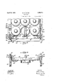
the body, includes :a floor 1Q., a transverse front mail 1.1 and three longitudinallyextending walls 12, two of which constitute the sides of thetruck body andthe .other oi' which constitutes .an intermediate partition. The longitudinal Walls 12 are spaced from each =.othe1-'=by :distances sdbstantial'ly .equal to multiples of fthedianfieters fof the i contain-- ers (indicated fat 113) lto lbe transported, .such distanrces, in the construction shfoWI-i :iin Figs. 1 3, .being fsuii'cient to enable the :containers 13 ito be :anranige'd snuglyV side :by side ifn rows of three. "Thus there is mo vopportunity der lateral displacement of the Vcontafin'ers when the .row-s 1are complete.
Each of t'hefouter Walls `is .provided with one, `and the xoen-ter Wall two, 'rows of socketslfis. `The 'individual sockets olf .these rows aireispaced apart by a 'distance substaln tial'ly equal to the diameter .of ione fof the containers 1&3, rand 'each socket is formed with a fpair-Yo `ears Ma spaced 'so sas to provide hetweentheinazslot lsb. Uertain ofthe .rows oit sodkets (1in lthe example shown in Figs. l to 3., the two lrowvson :the intermediate 1ongitudinal Wall :142) .have rods :extending through the ears 1de 'of vall the sockets of the new, .such yrods topferasting to Vclose the togo ends 'off the slots 11416 fof-the sockets.
The afrrangernentfshown fin Figs. 1 tor 3.
presents two aisles `for :the .reception ont the containers For each aisle il iprovi'de a .retaining ycross. han' 1'6. having at its ends up- Warmllyv extending brackets 1.7 formed with tongues .11'8 projedting outwardly therefrom. Each fcross fbarr is lof such v'dimens-ions (depending uaponfthe Width ofthe :aisle which it s to housed) that the tonguestS' will enter the ,slots 111% 'of the sockets. yonfeasch side olf the aisle, the retaining har being thereby secured in position. In `placingftl-re retaining bar position, fone of the tongues 18 thereof is inserted the-'slot 14h of 'one loithe sockets. carrried Iby the intermediate Wall 1Q, beneath the :rod E1'5. The 'oppositefend of `the retaining 4'hair is then swung down so that the tongue 18 at that end enters the slot of the socketionthe side Wall 12, being Asecured therein 'by a, pin 1 9 passing through suitable holes in the ears 14a. of the socket. The pin 19 is .preferably attached. to. the retaining bar by a chain 2,0, soas to tprevent,lloss,.and is provided with a pivQtedlatchJZl which can he turned at rglht angles to the ,pin (Fig. 2) when the latter 'has lbeen passed through the holes in the ears 14a, thereby preventing accidental disconnection of the pin.
It will be seen that by my invention the containers 13 may be stacked on end in rows in the truck, and the retaining bars then placed in position to hold in place the rearmost rows in the aisles. rIhus the containers are secured in position in such a manner that they cannot fall with any force against each other or against any part of the truck. Nevertheless the containers 'may be unloaded very conveniently, all that is necessary being that the retaining bar 16 at one end of an aisle be removed and replaced farther forward in the aisle after the containers have been unloaded. It is not essential that the rows of sockets 14 extend the whole length of the walls 12, as when the aisles have become partly emptied, the contents thereof can be shifted as a whole towards the rear of the truck, being then maintained in position by retaining bars engaging the front row like those engaging the rear row.
On some occasions, for example when some have been unloaded for delivery to a consumer, the number of containers in an aisle will be such that the rearmost row is not complete. To prevent material movement of the containers in these conditions, I provide dummies, of which a plurality may be car ried on the truck, available for employment if and when required. One of such dummies is shown in use in each aisle in Figs. 1 to 3. Each dummy comprises a ring 22 of a diameter corresponding with that of the containers 18, such ring being provided with a handle portion 23 and a hook portion 24 which is spaced away from the side of the ring 23 by a distance corresponding to the thickness of an upwardly extending web 25 with which the retaining bar 16 is provided. A dummy can be mounted in position on the retaining bar 16 by hooking the hook portion 24 thereof over the web 25 of the'retaining bar, such web then being enclosed between the hook portion 24 and the ring 22. The dummies are very easily placed in position and removed, and as many of them may be used as there'are vacancies in the last row of the containers. By this means, whatever the number of containers that is being transported at any time in an aisle of the truck, the containers are securely and firmly supported in such a way that there can be no material impacts between themselves or against parts of the truck.
The manner in which the walls and loading openings of truck bodies embodying my invention may be arranged is susceptible of wide variation. Three of the numerous possible arrangements other than that shown in Figs. 1 to 3 are illustrated in Figs. 4, 5 and 6 of the drawings. In Fig. 4 there is shown an arrangement in which the walls 12 are provided with gates 26 intermediate their ends, permitting loading or unloading at the sides of the truck as well as at the rear end. In such a case retaining bars might be employed to close the portions of the aisles in front of the gates 26 and other retaining bars employed to close both ends of the aisles at the rear of the gates 26. This would be of advantage in some cases, as dividing the truck into four compartments, each of which compartments might be loadedwith containers holding a particular compressed gas, thereby rendering any one of the several kinds of gas quickly available. Fig. 5 shows an arrangement similar to Fig. 4 but in which no intermediate wall 12 is employed, the truck not being divided into aisles. In Fig. 6 is illustrated an arrangement in which a transverse wall 27 1s arranged at a suitable Vdistance behind the front end wall 11 of the truck body so as to provide a transverse aisle which is closed by a side gate 28, the retaining bars being, of course, disposed transversely of this aisle. The back portion of the truck body is divided into two aisles like those described above in connection with Figs. 1 to 3. One or the other of these and other possible arrangements may be employed, depending upon the conditions in which the truck is to be used, and what is found convenient under the particular circumstances. rlhe arrangements permitting of side loading and unloading are sometimes of especial convenience, as also, upon occasion, are those permitting separation of containers holding different gases.
I claim:
1. In a truck body for transporting cylindrical containers of uniform diameter, the combination with a pair of members for confining a plurality of said containers in rows between them, a series of sockets mounted on each of said members, the individual sockets of each series being spaced apart by a distance substantially equal to the diameter of a container, and a retaining bar for engagement with an end row of said containers and adapted to be inserted between said members to enter one or another pair of said sockets in accordance with the position of the end row of containers; of a dummy of a width substantially equal to the diameter of said containers, said dummy having a hook for detachably mounting it upon said retain-V ing bar.
2. In a truck body for transporting cylindrical containers of uniform diameter, the combination with a pair of members for conining a plurality of said containers in rows between them, a series of sockets mounted on each of said members, the individual sockets of each series being spaced apart by a distance substantially equal to the diameter of a container, and a retaining bar for engagement with an end row of said containers and adapted to be inserted between said members to enter one or another pair of said sockets in accordance with the position of the end row of containers, said retaining bar being provided with an upwardly extending web; of a dummy detaohably connected with said retaining bar and comprising a ring of a diameter substantially the same as that of said containers and a hook spaced from said ring for the admission of the webV of said retaining bar.
In testimony whereof, I si my name. WILLIAM G. MAYER.
Priority Applications (1)
| Application Number | Priority Date | Filing Date | Title |
|---|---|---|---|
| US460367A US1854711A (en) | 1930-06-11 | 1930-06-11 | Truck body |
Applications Claiming Priority (1)
| Application Number | Priority Date | Filing Date | Title |
|---|---|---|---|
| US460367A US1854711A (en) | 1930-06-11 | 1930-06-11 | Truck body |
Publications (1)
| Publication Number | Publication Date |
|---|---|
| US1854711A true US1854711A (en) | 1932-04-19 |
Family
ID=23828420
Family Applications (1)
| Application Number | Title | Priority Date | Filing Date |
|---|---|---|---|
| US460367A Expired - Lifetime US1854711A (en) | 1930-06-11 | 1930-06-11 | Truck body |
Country Status (1)
| Country | Link |
|---|---|
| US (1) | US1854711A (en) |
Cited By (9)
| Publication number | Priority date | Publication date | Assignee | Title |
|---|---|---|---|---|
| US2834304A (en) * | 1954-09-21 | 1958-05-13 | Evans Prod Co | Freight loading apparatus |
| US4542774A (en) * | 1982-09-09 | 1985-09-24 | Aga Ab | Delivery system and method for pressurized gas |
| US4641755A (en) * | 1985-06-10 | 1987-02-10 | The United States Of America As Represented By The Secretary Of The Navy | Projectile stowage rack |
| US5154556A (en) * | 1990-08-30 | 1992-10-13 | Camco International Inc. | Retention device for metal cylindrical containers |
| US5423590A (en) * | 1993-07-21 | 1995-06-13 | Scullin; Jan J. | Transport trailer and method for transporting cylindrical containers |
| US7275902B1 (en) | 2004-04-29 | 2007-10-02 | Welding Company Of America | Gas cylinder delivery system |
| US20100072154A1 (en) * | 2008-09-23 | 2010-03-25 | Articulation, Inc. | Compartment divider assembly |
| US20190380491A1 (en) * | 2018-06-19 | 2019-12-19 | Glenn Ehrgott | Tire rack securing system |
| CN111186356A (en) * | 2020-01-14 | 2020-05-22 | 宋和平 | Hydrogen transport vehicle |
-
1930
- 1930-06-11 US US460367A patent/US1854711A/en not_active Expired - Lifetime
Cited By (10)
| Publication number | Priority date | Publication date | Assignee | Title |
|---|---|---|---|---|
| US2834304A (en) * | 1954-09-21 | 1958-05-13 | Evans Prod Co | Freight loading apparatus |
| US4542774A (en) * | 1982-09-09 | 1985-09-24 | Aga Ab | Delivery system and method for pressurized gas |
| US4641755A (en) * | 1985-06-10 | 1987-02-10 | The United States Of America As Represented By The Secretary Of The Navy | Projectile stowage rack |
| US5154556A (en) * | 1990-08-30 | 1992-10-13 | Camco International Inc. | Retention device for metal cylindrical containers |
| US5423590A (en) * | 1993-07-21 | 1995-06-13 | Scullin; Jan J. | Transport trailer and method for transporting cylindrical containers |
| US7275902B1 (en) | 2004-04-29 | 2007-10-02 | Welding Company Of America | Gas cylinder delivery system |
| US20100072154A1 (en) * | 2008-09-23 | 2010-03-25 | Articulation, Inc. | Compartment divider assembly |
| US20190380491A1 (en) * | 2018-06-19 | 2019-12-19 | Glenn Ehrgott | Tire rack securing system |
| US10980342B2 (en) * | 2018-06-19 | 2021-04-20 | Glenn Ehrgott | Tire rack securing system |
| CN111186356A (en) * | 2020-01-14 | 2020-05-22 | 宋和平 | Hydrogen transport vehicle |
Similar Documents
| Publication | Publication Date | Title |
|---|---|---|
| US1854711A (en) | Truck body | |
| US1341996A (en) | Freight loading and unloading crane | |
| US1875107A (en) | Parcel carrier for baby carriages | |
| US1360412A (en) | Interchangeable-unit car | |
| US1536751A (en) | Vehicle tow bar | |
| US679567A (en) | Means for handling baggage. | |
| US1521156A (en) | Vehicle body | |
| US595056A (en) | Dumping-wagon | |
| US1446799A (en) | Truck | |
| US3052485A (en) | Impact gate | |
| US1197021A (en) | Wagon attachment. | |
| US1994399A (en) | Device for the transportation of goods | |
| US1858408A (en) | Freight car | |
| US1072887A (en) | Freight-car or the like. | |
| US658365A (en) | Hog or cattle holding rack. | |
| US480308A (en) | Merchandising-car | |
| US1838175A (en) | Guard for poultry cars | |
| US125592A (en) | Improvement in wagons for fountains charged with soda-water | |
| US1699524A (en) | Poultry car | |
| US241545A (en) | kelly | |
| US2984371A (en) | Dispensing carton carrier for vehicles | |
| US1670738A (en) | Ballot holder for trucks | |
| DE3509325A1 (en) | FOLDABLE PACK BAG FOR SHOPPING CART OF CONSUMER MARKETS | |
| US556800A (en) | Car for transporting live stock | |
| US165632A (en) | Improvement in cart-chutes |