US185458A - Improvement in steam pile-drivers - Google Patents
Improvement in steam pile-drivers Download PDFInfo
- Publication number
- US185458A US185458A US185458DA US185458A US 185458 A US185458 A US 185458A US 185458D A US185458D A US 185458DA US 185458 A US185458 A US 185458A
- Authority
- US
- United States
- Prior art keywords
- steam
- pile
- hammer
- cylinder
- piston
- Prior art date
- Legal status (The legal status is an assumption and is not a legal conclusion. Google has not performed a legal analysis and makes no representation as to the accuracy of the status listed.)
- Expired - Lifetime
Links
- 239000002184 metal Substances 0.000 description 4
- 229910052751 metal Inorganic materials 0.000 description 4
- XEEYBQQBJWHFJM-UHFFFAOYSA-N Iron Chemical compound [Fe] XEEYBQQBJWHFJM-UHFFFAOYSA-N 0.000 description 2
- 229910000754 Wrought iron Inorganic materials 0.000 description 2
- 230000000284 resting effect Effects 0.000 description 2
- 241001052209 Cylinder Species 0.000 description 1
- CWYNVVGOOAEACU-UHFFFAOYSA-N Fe2+ Chemical compound [Fe+2] CWYNVVGOOAEACU-UHFFFAOYSA-N 0.000 description 1
- 229940000425 combination drug Drugs 0.000 description 1
- 239000013013 elastic material Substances 0.000 description 1
- 230000005484 gravity Effects 0.000 description 1
- 229910052742 iron Inorganic materials 0.000 description 1
- 230000001105 regulatory effect Effects 0.000 description 1
- 238000004326 stimulated echo acquisition mode for imaging Methods 0.000 description 1
- 238000009966 trimming Methods 0.000 description 1
Images
Classifications
-
- E—FIXED CONSTRUCTIONS
- E02—HYDRAULIC ENGINEERING; FOUNDATIONS; SOIL SHIFTING
- E02D—FOUNDATIONS; EXCAVATIONS; EMBANKMENTS; UNDERGROUND OR UNDERWATER STRUCTURES
- E02D7/00—Methods or apparatus for placing sheet pile bulkheads, piles, mouldpipes, or other moulds
- E02D7/02—Placing by driving
- E02D7/06—Power-driven drivers
- E02D7/10—Power-driven drivers with pressure-actuated hammer, i.e. the pressure fluid acting directly on the hammer structure
Definitions
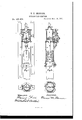
- the object of my invention is the improvement of that class of pile-hammers in which the direct action of steam is used by attaching hammer to the piston-rod of a steam-cylinder, suspended inv leaders of ordinary piledrivers.
- Figure 1 represents a full front view of ham-. mer resting on pile p and sliding in leaders at.
- Fig. 2 represents a vertical section through same, showing arrangement of valve motion, steam-cylinder, &c., and manner of connecting piston-rod n to hammer 0 made in two parts, and held together by key y, piston-rod having two wooden rings, 00, or other elastic material, placed above and below, to relieve jar upon piston m.
- Fig. 3 is a horizontal section through cylinder 1), showing manner of connecting same to stay 8 by means of bolts; also, lower cylinder head or flange w, forming guides to retain hammer in leaders 0,.
- Fig. 4 is a horizontal section through tubular frame 17, showing manner of connecting same to stay 8 by means of rivets having countersunk heads at either end, and running through to inside of guides, upon which the hammer slides in its movement; also, shows top view of cone or base q, and manner of bolting same to frame, said cone being also riveted by means of countersunk rivets to stays s.
- Said plunger 3 has twoconnections from lower side of same, one by means of small pipe and cock 1, with steam-chest, and the other byflmcansof valve 1" with open air.
- the plungers e and g are connected by a rod which is secured to slide-valve h, an upward or downward movement ofplungers being communicated by On steam entering steam-chest 0, the cock l b'eing partially open, steam is admitted to lower side of plunger 9, thereby equalizing pressure ontop and bottom sidesof said plunger, which therefor'e exerts no influence on slide-valve, but,
- valve g h e operated by steam-pressure, in com-bination with cylinders 'df and pipeand cock l on the steam-chest c,:t'or regulatingtheribrce of blow of the pile-driver, all constructed and arranged substantially as shown and specified.
- Thetubular frame It, connected with the cylinder 12 and ring q, constructed and arranged substantially as shown, and for the a purpose set forth.
Landscapes
- Engineering & Computer Science (AREA)
- Life Sciences & Earth Sciences (AREA)
- General Life Sciences & Earth Sciences (AREA)
- Mining & Mineral Resources (AREA)
- Paleontology (AREA)
- Civil Engineering (AREA)
- General Engineering & Computer Science (AREA)
- Structural Engineering (AREA)
- Treatment Of Fiber Materials (AREA)
Description
T. M. SKINNER.
STEAM FILE-DRIVER.
Patented Dec. 19, 1876.
Fig.2.
LII
ynesses. I nve ntor.
7w m mm W a? a;
THE GRAPHIC COJLY UNITED S'ra'rs THOMAS M. SKINNER, OF QHlGAGO, ILLINOIS;
IMPROVEMENT IN STEAM PlLE-DRIVERS.
Specification forming part of Letters Patent No. 185,458, dated December 19, 1876; application filed September 28, 1876.
To all whom it may concern.-
Be it known that I, THOMAS MINER SKIN- NER, of Chicago, in the county of Cook and State of Illinois, have invented a new and useful Improvement in Pile-Driving Machines, which improvement is fully set forth in the following specification, reference being had to the accompanying drawings.
The object of my invention is the improvement of that class of pile-hammers in which the direct action of steam is used by attaching hammer to the piston-rod of a steam-cylinder, suspended inv leaders of ordinary piledrivers.
First, by using a hammer which receives its impetus both from its own weight and by the direct downward pressure of steam on the piston attached, the reaction of steampressure being overcome by the weight of metal in cylinder and frame, said weight being greater than steam-pressure on piston, and such as to prevent frame of hammer lifting from pile at the termination of the downward stroke.
Second, by the use of a cast or-wrought iron (or other metal) ring or base attached to frame of steam pile-hammers, said ring or base having aconical or tapering hole through center,
which, fitting or resting on head of pile, forms a support for hammer, and protection to pile from splitting, and obviates the use of the usual wrought-iron pile-band and all trimming or chopping on head of pile.
Third, in the combination, with steam pilehammers, of a valve motion, having no levers, cams, or other appliances liable to disorder from the excessive jarring to which they are subject, and whose motion is positively regulated by the valve or cook Z, (shown on drawing,) thereby enabling the operator tov strike light or heavy blows at pleasure.
Fourth, by the tubular form of frame and arrangement of connections with cylinder, insuring the greatest strength, and preventing all twisting, springing, or binding of piston, piston-rod, or hammer, and holding the pile in the exact position where needed.
By using steam both at the downward as well as the upward stroke of the piston I am enabled to use a lighter hammer at shorter stroke, greater speed, and in a position farther from vertical than where action of gravity alone is relied upon, the force of the blow being only limited by the amount and weight of metal in the frame and cylinder.
By connecting cylinder and frame to the iron stay running from top to bottom of same the entire machine is firmly held together, relieving all excessive strain on bolts connecting bottom of cylinder and frame, and by the manner in which said stay is connected to cylinder by means of bolts the same can-be readily disengaged when required.
The operation can be seen by reference to the accompanying drawings.
Figure 1 represents a full front view of ham-. mer resting on pile p and sliding in leaders at.
Fig. 2 represents a vertical section through same, showing arrangement of valve motion, steam-cylinder, &c., and manner of connecting piston-rod n to hammer 0 made in two parts, and held together by key y, piston-rod having two wooden rings, 00, or other elastic material, placed above and below, to relieve jar upon piston m.
Fig. 3 is a horizontal section through cylinder 1), showing manner of connecting same to stay 8 by means of bolts; also, lower cylinder head or flange w, forming guides to retain hammer in leaders 0,.
Fig. 4 is a horizontal section through tubular frame 17, showing manner of connecting same to stay 8 by means of rivets having countersunk heads at either end, and running through to inside of guides, upon which the hammer slides in its movement; also, shows top view of cone or base q, and manner of bolting same to frame, said cone being also riveted by means of countersunk rivets to stays s.
The entire machine being raised to top of leaders by a rope passing from ring 1;, attached to top cylinder-head u to the drum of an ordinary hoisting-engine, allows the pile p to be placed in position by means of a line running to winch. The hammer is then carefully lowered until cone q rests on pile. The rope or hammer line is then relieved of all strain, and allowed to hang loose in position. The steampipe k having been connected to boiler by means of rubber hose, or a flexible jointed pipe, steam is turned on, filling steam-chest means of said rod to slide-valve.
0 at top and bottom, of which are two cylinders, d and 'f, the smallercylinderd being closed by small plunger 0, having an open air connection on top side, and the larger cylin der f being closed by plunger g, whose area shall be about twice that of e. Said plunger 3 has twoconnections from lower side of same, one by means of small pipe and cock 1, with steam-chest, and the other byflmcansof valve 1" with open air. The plungers e and g are connected by a rod which is secured to slide-valve h, an upward or downward movement ofplungers being communicated by On steam entering steam-chest 0, the cock l b'eing partially open, steam is admitted to lower side of plunger 9, thereby equalizing pressure ontop and bottom sidesof said plunger, which therefor'e exerts no influence on slide-valve, but,
there being a strong upward pressure on iplungm 0, said plungerrises, carrying with it slidevalve h and plunger 9, thereby opening lower steam-port of cylinder 1), and'admitting steam on lower side of piston to, which, by means of piston-rod n, raises hammer" 0 until said -hammer comes in contact with lever e, which,
raising valve 1", releases "pressure-from lower side of plunger g, and said plungerbeingiotv 1 double the area of plunger e, and consequently having double the pressure on its upper side,
ing steainon lower side through pipe '5 ,'icausing said piston m, piston-rod 7n, and hammer 0, all attached, to drop suddenly on headiof pile. As hammer 0, on its downward stroke,
passes below lever z, releasingsaid lever and allowing valve 1' to drop to its @seat thereby shutting 011' all communication bet-ween the open air and lower side of plunger g,-it causes the steam, which is passing through the pipe I, to again equalize the pressure on both sides of plunger 9, and, as before, plunger 0 exerts its which means a lighter blow is struck without reducing rapidity of movement of hammer,
thereby enabling the operator to vary his blow for different classes of work.
I claim as my invention-- -l.The metal frame t, constructed as described, in combination with the cylinder?) and valve 9 h e, wheniarranged and operated as shown and specified.
2. The conical base or ring q forsu pporting =the pile-driveron the pile and protecting-the same, in combination with the frame t agd cylinderb, substantially as specified.
3. The valve g h e operated by steam-pressure, in com-bination with cylinders 'df and pipeand cock l on the steam-chest c,:t'or regulatingtheribrce of blow of the pile-driver, all constructed and arranged substantially as shown and specified.
, 4. Thetubular frame It, connected with the cylinder 12 and ring q, constructed and arranged substantially as shown, and for the a purpose set forth.
- THOS. M. SKINNER.
Witnesses:
HARRY Fox, *WILLEND S. GARKIN.
Publications (1)
| Publication Number | Publication Date |
|---|---|
| US185458A true US185458A (en) | 1876-12-19 |
Family
ID=2254864
Family Applications (1)
| Application Number | Title | Priority Date | Filing Date |
|---|---|---|---|
| US185458D Expired - Lifetime US185458A (en) | Improvement in steam pile-drivers |
Country Status (1)
| Country | Link |
|---|---|
| US (1) | US185458A (en) |
-
0
- US US185458D patent/US185458A/en not_active Expired - Lifetime
Similar Documents
| Publication | Publication Date | Title |
|---|---|---|
| US2068045A (en) | Piston pile driver | |
| US3583499A (en) | Hydraulic pile extractor | |
| US185458A (en) | Improvement in steam pile-drivers | |
| US1077469A (en) | Power-driven hammer. | |
| US859629A (en) | Stamp-mill. | |
| US1173996A (en) | Apparatus for extracting piles. | |
| US284282A (en) | Pile-driver | |
| US961039A (en) | Pump. | |
| US705097A (en) | Copying-press. | |
| US208448A (en) | Improvement in rock-drills | |
| US228557A (en) | Operating submarine gr | |
| US836630A (en) | Punch or riveter. | |
| US650691A (en) | Ash or other hoist. | |
| US5172A (en) | Jambs nasmyth | |
| US789324A (en) | Automatic jet-pipe for excavation. | |
| US659489A (en) | Dredge. | |
| US665473A (en) | Lifting device for press-rolls of paper-making machinery. | |
| US398491A (en) | Steam-actuated valve | |
| US755467A (en) | Hydraulic ram. | |
| US1314257A (en) | Hydraulic hoist for ash-cans and the like | |
| US80550A (en) | David joy | |
| US484223A (en) | Auxiliary valve for elevators | |
| US390627A (en) | James todd | |
| US208282A (en) | Improvement in hydraulic elevators | |
| US1141054A (en) | Governor attachment. |