US1854588A - Merry-go-round - Google Patents
Merry-go-round Download PDFInfo
- Publication number
- US1854588A US1854588A US322038A US32203828A US1854588A US 1854588 A US1854588 A US 1854588A US 322038 A US322038 A US 322038A US 32203828 A US32203828 A US 32203828A US 1854588 A US1854588 A US 1854588A
- Authority
- US
- United States
- Prior art keywords
- merry
- round
- rods
- seat
- wheel
- Prior art date
- Legal status (The legal status is an assumption and is not a legal conclusion. Google has not performed a legal analysis and makes no representation as to the accuracy of the status listed.)
- Expired - Lifetime
Links
- 238000010276 construction Methods 0.000 description 5
- 238000005266 casting Methods 0.000 description 3
- 239000000463 material Substances 0.000 description 3
- 239000002184 metal Substances 0.000 description 2
- 239000004568 cement Substances 0.000 description 1
- 235000020030 perry Nutrition 0.000 description 1
- 239000002023 wood Substances 0.000 description 1
Images

Classifications
-
- A—HUMAN NECESSITIES
- A63—SPORTS; GAMES; AMUSEMENTS
- A63G—MERRY-GO-ROUNDS; SWINGS; ROCKING-HORSES; CHUTES; SWITCHBACKS; SIMILAR DEVICES FOR PUBLIC AMUSEMENT
- A63G1/00—Roundabouts
- A63G1/12—Roundabouts rotated by the passengers themselves
Definitions
- This invention relates to merry-go-rounds and the object of the invention is to provide a merry-go-round of the type which may be easily operated by one or more of the occupants being particularly adapted for use by children and which is to be known as a Kiddy-Ped-About.
- Another object of the invention is to provide an occupant operated merry-go-round which is simple in construction and which may be manufactured from inexpensive materials.
- Another object of the invention is to provide a Inerry-go-round which is of such size that it may be set up in a small space, thus permitting of its use as a healthful and amusing exercising device for children and one which may be set up within the confines of their home yards.
- Another object of the invention is to provide a merry-go-round having a minimum number of parts, which are strong in construction, certain in operation, and which will not often need repair even when constantly used.
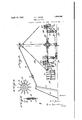
- FIG. 1 is a plan of a merry-go-round embodying my invention
- Fig. 2 is a section on the line 22 of Fig. l, partly broken away;
- Fig. 3 is a perspective of the back for the operators seat and the rear portion of the seat;
- Fig. 4 is perspective of the front portion of the operators seat andsthe support therefor;
- Fig. 5 is a plan of the spike tooth wheel comprising one element of my invention; and Fig. 6 is a vertical section of the same.
- 1 indicates the central post which is supported on a lower casting 2, the casting being suitably sunk into the ground or otherwise firmly fixed.
- a cap 8 is provided for the top of the post. Ball bearings are Renewed August 21, 1931.
- guy wires 4 Attached to and extending outwardly from the cap 8 are guy wires 4 which are suitably anchored in the ground as at 5. Supporting poles 6 are provided for the guy wires and turn buckles 7 for drawing them taut and structions of the same material than the rods 10, since the former rods support the larger proportion of the weight the operating elements, as will presently appear.
- a continuous member 11 formed of a series of rods, this construction serving to strengthen the structure and also provide a means, in connection with the rods 9 and 10, for supporting the seats 12 adjacent the outer ends of the radiating rods.
- These seats12 may be of any, desired design being preferably provided with means, such as a sloping seat and retaining arms, for preventing the rider from being thrown out of his seat during the operation of the merry-go-round.
- one or more seats 13 for the operators are mounted on the rods 9 and 10.
- metal bearings for the crank shaft may be provided on the bars.
- crank shaft is formed to provide pedals 16. Between two of the bars 14 an op-" erating wheel 1'? is mounted on the crank shaft .near its inner end. This wheel 17 is provided with spike teeth 18, each tooth having a pointed end, the purpose of which will be apparent as the description proceeds.
- the wheel 17 is adapted to travel on a track of special construction.
- the track comprises a channel bar 20, concentrically arranged with respect to the post 1. Extending between the sides of the bar 20 at regular intervals are rods 21, which provide spaces into which the spike teeth of the wheel enter.
- the track is suitably secured to the ground or supporting surface, as by embedding it in cement.
- the operator seated on the seat 13 operates the pedals to turn the wheel 17, the spike teeth enter the spaces between the tie rods, the step-by-step movement of the wheel rotating the entire device, including the seat mounting structure and the seats.
- the track may be made from two circular bands instead of a channel bar.
- Additional wires for supporting and steadying the structure are shown at 22 which extend from the post to the radial bars.
- This means for adjusting the seat comprises the back 23 which is secured to the radial rod 9.
- the seat back is formed of a series of slats 24 between the outer pairs of which are a series of horizontal nails or supporting bars 25.
- On the adjacent rod 10 is mounted an upwardly extending support 26 provided with a series of bars 27.
- the operators seat is provided at one end with a pair of hooks 28 which are adapted to engage over the nails or bars 25, while the narrowed front portion 29 of the seat is adapted to rest on one of the bars 27.
- the merry-go-round, as shown, is preferably constructed almost entirely from wood, thus cheapening the structure and permit-- ting of the renewal of any parts at minimum expense.
- a circular track In a merry-go-round, a circular track, a supporting post concentrically mounted therewith, a plurality of rods radiating from said post, a wheel depending from one of said rods adapted to cooperate with said track to rotate said post and radial rods, an upwardly extending back on said mentioned rod, an upwardly extending support on the next adjacent rod, and an operators seat adapted to be secured between said last mentioned rods, the rear of said seat being adjustably mounted on said upwardly extending back and the front of said seat being adjustably mounted on said support.
Landscapes
- Seats For Vehicles (AREA)
Description
s-Sheet l R T JONES Original Filed Nov. 28, 1928 2 Sheet A fil 19, 1932.
April 19, 1932. R T JONES 1,854,588
- MERRY-GQ-ROUND Original Filed Nov. 26, 1928 2 Shets-Sheet 2 O O O 000 Patented Apr. 19, 1932 ice R T JONES, 0F PERRY, IOWA MERRY-GO-ROUND Application filed November 26, 1928, Serial No. 322,038.
This invention relates to merry-go-rounds and the object of the invention is to provide a merry-go-round of the type which may be easily operated by one or more of the occupants being particularly adapted for use by children and which is to be known as a Kiddy-Ped-About.
Another object of the invention is to provide an occupant operated merry-go-round which is simple in construction and which may be manufactured from inexpensive materials.
Another object of the invention is to provide a Inerry-go-round which is of such size that it may be set up in a small space, thus permitting of its use as a healthful and amusing exercising device for children and one which may be set up within the confines of their home yards.
Another object of the invention is to provide a merry-go-round having a minimum number of parts, which are strong in construction, certain in operation, and which will not often need repair even when constantly used.
I accomplish the above and other objects of the invention by means of the construction shown in the accompanying drawings, in which Fig. 1 is a plan of a merry-go-round embodying my invention;
Fig. 2 is a section on the line 22 of Fig. l, partly broken away;
Fig. 3 is a perspective of the back for the operators seat and the rear portion of the seat;
Fig. 4 is perspective of the front portion of the operators seat andsthe support therefor;
Fig. 5 is a plan of the spike tooth wheel comprising one element of my invention; and Fig. 6 is a vertical section of the same.
On the drawings, in which like reference characters indicate like parts on all of the views thereof, 1 indicates the central post which is supported on a lower casting 2, the casting being suitably sunk into the ground or otherwise firmly fixed. A cap 8 is provided for the top of the post. Ball bearings are Renewed August 21, 1931.
provided between the casting 2 and the post and between the cap 3and the post.
Attached to and extending outwardly from the cap 8 are guy wires 4 which are suitably anchored in the ground as at 5. Supporting poles 6 are provided for the guy wires and turn buckles 7 for drawing them taut and structions of the same material than the rods 10, since the former rods support the larger proportion of the weight the operating elements, as will presently appear.
Connecting the rods 9 and 10 is a continuous member 11, formed of a series of rods, this construction serving to strengthen the structure and also provide a means, in connection with the rods 9 and 10, for supporting the seats 12 adjacent the outer ends of the radiating rods. These seats12 may be of any, desired design being preferably provided with means, such as a sloping seat and retaining arms, for preventing the rider from being thrown out of his seat during the operation of the merry-go-round.
Within the circumference of the continuous member 11, one or more seats 13 for the operators are mounted on the rods 9 and 10. Depending from the rods 9 on which the operators seat is mounted are bars 14, suit-" ably spaced so as to support a crank shaft 15. If desired, metal bearings for the crank shaft may be provided on the bars.
The crank shaft is formed to provide pedals 16. Between two of the bars 14 an op-" erating wheel 1'? is mounted on the crank shaft .near its inner end. This wheel 17 is provided with spike teeth 18, each tooth having a pointed end, the purpose of which will be apparent as the description proceeds. The
of the seats and wheel is formed from a plurality of these teeth secured between plates 19.
The wheel 17 is adapted to travel on a track of special construction. The track comprises a channel bar 20, concentrically arranged with respect to the post 1. Extending between the sides of the bar 20 at regular intervals are rods 21, which provide spaces into which the spike teeth of the wheel enter. The track is suitably secured to the ground or supporting surface, as by embedding it in cement.
\Vhen the operator, seated on the seat 13 operates the pedals to turn the wheel 17, the spike teeth enter the spaces between the tie rods, the step-by-step movement of the wheel rotating the entire device, including the seat mounting structure and the seats. If preferable, the track may be made from two circular bands instead of a channel bar.
Additional wires for supporting and steadying the structure are shown at 22 which extend from the post to the radial bars.
In order that the merry-go-round may be operated by persons of different ages and sizes, I have provided a means for adjustingthe operators seat 13 so that it may be raised and lowered as desired. This means for adjusting the seat comprises the back 23 which is secured to the radial rod 9. The seat back is formed of a series of slats 24 between the outer pairs of which are a series of horizontal nails or supporting bars 25. On the adjacent rod 10 is mounted an upwardly extending support 26 provided with a series of bars 27. The operators seat is provided at one end with a pair of hooks 28 which are adapted to engage over the nails or bars 25, while the narrowed front portion 29 of the seat is adapted to rest on one of the bars 27.
While I am aware that it has previously been proposed in a somewhat similar apparatus to provide a gear wheel meshing with a toothed track for operating the apparatus, it is novel, so far as I am aware, to provide atrack that is formed with open spaces and a wheel having spike teeth which operates therein, which structure obviates the obvious difficulties that occur when dirt collects on a gear wheel, and when the intermeshing parts become worn and thus interfere with the movement of the device and often render it totally inoperative.
The merry-go-round, as shown, is preferably constructed almost entirely from wood, thus cheapening the structure and permit-- ting of the renewal of any parts at minimum expense.
I do not wish to limit myself to the use of any particular material, since it is obvious that many of the parts could be constructed of metal.
Having thus described my invention what I claim as new and desire to secure by Letters Patent of the United States, is:
In a merry-go-round, a circular track, a supporting post concentrically mounted therewith, a plurality of rods radiating from said post, a wheel depending from one of said rods adapted to cooperate with said track to rotate said post and radial rods, an upwardly extending back on said mentioned rod, an upwardly extending support on the next adjacent rod, and an operators seat adapted to be secured between said last mentioned rods, the rear of said seat being adjustably mounted on said upwardly extending back and the front of said seat being adjustably mounted on said support.
In testimony whereof I hereunto atiix my signature.
R T JONES.
Priority Applications (1)
| Application Number | Priority Date | Filing Date | Title |
|---|---|---|---|
| US322038A US1854588A (en) | 1928-11-26 | 1928-11-26 | Merry-go-round |
Applications Claiming Priority (1)
| Application Number | Priority Date | Filing Date | Title |
|---|---|---|---|
| US322038A US1854588A (en) | 1928-11-26 | 1928-11-26 | Merry-go-round |
Publications (1)
| Publication Number | Publication Date |
|---|---|
| US1854588A true US1854588A (en) | 1932-04-19 |
Family
ID=23253127
Family Applications (1)
| Application Number | Title | Priority Date | Filing Date |
|---|---|---|---|
| US322038A Expired - Lifetime US1854588A (en) | 1928-11-26 | 1928-11-26 | Merry-go-round |
Country Status (1)
| Country | Link |
|---|---|
| US (1) | US1854588A (en) |
-
1928
- 1928-11-26 US US322038A patent/US1854588A/en not_active Expired - Lifetime
Similar Documents
| Publication | Publication Date | Title |
|---|---|---|
| US3598406A (en) | Gymnastic apparatus | |
| US1854588A (en) | Merry-go-round | |
| DE69611734T2 (en) | ROUND TRIP FOR AMUSEMENT FAIR | |
| US1731658A (en) | Play and exercising device | |
| US4251069A (en) | Child recreation structure | |
| US1818545A (en) | Tent | |
| US1791227A (en) | Merry-go-round | |
| US1675249A (en) | Apparatus for supporting and straining lawn-tennis and like nets | |
| US1714247A (en) | Swing | |
| US1733919A (en) | Chair | |
| US1720397A (en) | Roundabout | |
| DE1111554B (en) | Climbing frame for children that can be anchored and dismantled in the ground | |
| US1812946A (en) | Roundabout | |
| US2644674A (en) | Drive-over metal cattle gate | |
| US2255175A (en) | Amusement device | |
| US1752208A (en) | Stadium chair | |
| US968803A (en) | Amusement apparatus. | |
| US1760811A (en) | Occupant-propelled carrousel | |
| US2066448A (en) | Starting gate with self-aligning spiked stall partitions | |
| US1626142A (en) | Playground slide | |
| US670706A (en) | Exercising-machine. | |
| DE202009007472U1 (en) | Trampoline with a standing platform | |
| US2066447A (en) | Starting gate | |
| US770121A (en) | Roundabout. | |
| US3602500A (en) | Seesaw toy |