US1854579A - Safety razor - Google Patents
Safety razor Download PDFInfo
- Publication number
- US1854579A US1854579A US567084A US56708431A US1854579A US 1854579 A US1854579 A US 1854579A US 567084 A US567084 A US 567084A US 56708431 A US56708431 A US 56708431A US 1854579 A US1854579 A US 1854579A
- Authority
- US
- United States
- Prior art keywords
- guard
- plate
- frame
- stropping
- blade
- Prior art date
- Legal status (The legal status is an assumption and is not a legal conclusion. Google has not performed a legal analysis and makes no representation as to the accuracy of the status listed.)
- Expired - Lifetime
Links
Images
Classifications
-
- B—PERFORMING OPERATIONS; TRANSPORTING
- B26—HAND CUTTING TOOLS; CUTTING; SEVERING
- B26B—HAND-HELD CUTTING TOOLS NOT OTHERWISE PROVIDED FOR
- B26B21/00—Razors of the open or knife type; Safety razors or other shaving implements of the planing type; Hair-trimming devices involving a razor-blade; Equipment therefor
- B26B21/40—Details or accessories
- B26B21/50—Means integral with, or attached to, the razor for stropping the blade
Definitions
- My invention relates to safety razors and aims to provide certain improvements there- 1n.
- the present invention is particularly directed to that type of safety razor comprising a blade holder mounted on a spindle pivoted in a frame and in geared relationship with a roller adapted to be rotated in alternate directions by application to a rigid stropping medium.
- a razor of this type possesses the advantage that the pressure exerted by the blade on the stropping medium is directly proportional to the downward thrust exerted by the user on the spindle or roller, which contacts with the stropping medium.
- the object of this invention is to provide a safety razor which is of simple construction with few number of parts, which is capable of cheap manufacture and will not readily go out of order.
- I provide safety razor wherein the guard-plate is retained in the shaving position by a spring and is adapted to be held in the stropping position against the action of said spring by a catch associated with said frame.
- I may hold the guard-plate in either the shaving 0r stropping positions by friction derived either from the pivot of the guard-plate or by the guard plate being in frictional contact with the frame itself.
- I may provide a safety razor wherein the guard-plate in acted upon by a spring adapted to hold it in either of two positions, namely the stopping or the shaving position.
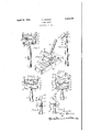
- Figure 1 is a front elevation of one form of safety razor
- Figure 2 is a sectional side elevation of F igure 1;
- Figure 3 is a perspective view showing the position of the razor whilst stropping the blade
- Figure 4 is an alternative construction wherein the guard-plate is frictionally controlled
- Figure 5 is a front elevation of yet another modification wherein the guard-plate is spring controlled
- Figure 6 is a part sectional view of Figure 5 showing the guard-plate in the shaving position.
- Figure 7 is a similar view showing the guard-plate in the stropping position.
- the safety razor comprises a handle 2 secured to a U-shaped frame 3, comprising end and side portions. Towards the extremities of the forked ends of the frame is pivotally mounted a spindle at carrying the blade holder or clip 5 adapted to grip the blade 6.
- the blade holder spindle 4 is furnished with a spur pinion 7 in geared relationship with a second gear 8 carried on a roller 9 (the gear 8 being directly behind pinion 7, as viewed in Fig. 1.)
- a guardplate 10 is mounted on spindle 11 in the frame 3.
- the guard-plate is furnished with a helical spring 12 in such a manner as to cause it to turn about its pivot and press against the blade 6 which is engaged by hook shaped portions 13 on the guard-plate 10.
- a projecting lug 14.- is formed on one member of the frame 3, which is adapted to engage the edge of the guard-plate 10 and thus keep the latter clear of the path swept by the blade during stropping.
- the guard-plate 10 is provided with projections 15 adapted to bear on the sides of the frame and prevent the guard-plate from swinging through between the side members of the frame whilst not in engagement with the blade 6.
- the guardplate 10 is pivoted to the frame with a certain degree of friction so that the guard-plate will remain in any position in which it is placed. Said friction may be produced either through the medium of the pivotal bearings 11 of the guard-plate 10, or this friction may be produced or assisted by mounting the guard-- plate as shown, in such a position on the main frame, that the portion 16 thereof is brought into frictional engagement with the main frame.
- Figs. 5, 6 and 7 illustrate yet another modification according to which the guardplate is adapted to be held in the shaving position or in the strcpping position by means of a sprin
- a slightly curved lear spring 29 is held centrally by means of a rivet 21 which also serves to hold the frame to the handle 2.
- he extremities of the leaf spring 20 are adapted to bear on cams 22 formed on the guard-plate 10, the arrangement being such that the spring 20 will. hold the guard-plate in either of the two positions in which it is placed, that is to say, it will hold it in the shaving position or it will hold it in the stropping position.
- the former position is shown in Fig. 6, whilst the latter position is shown in Fig. 7.
- the sides of the frame 3 are provided with extending cheeks of projections 2% adapted to it astride the strop and constitute a guide to prevent the razor slipping off sideways.
- the action of these cheeks 2-l is clearly shown in 3.
- a safety razor comprising in combinat1on a frame, a blade holder pivotally mounted in said frame, a roller in geared relationship with said blade holder and adapted to be rotated in alternate directions by appli cation to a rigid stropping medium, extensionp on said frame adapted to [it astride said stropping medium and act as guides to prevent the razor slipping off during the stropping operation, a guard-plate mounted on a pivot pin in said frame and means for holding the said guard-plate in the respective shaving and stropping positions by friction derived from the said guard-plate pivot pin.
- a safety razor comprising in combination a frame, a blade holder pivotally mounted in said frame, a roller in geared relationship with said blade holder and adapted to be rotated in alternate directions by application to a rigid stropping medium, extensions on said frame adapted to fit astride said stropping medium and act as guides to prevent the razor slipping off during the stropping operation, a guard-plate mounted on a pivot pin in said frame and means for holding the said guard-plate in the respective shaving and stropping positions by friction due to said guard-plate being in frictional contact with said frame.
- a safety razor comprising, a substantially U-shaped frame having end and side portions, a blade holder, means pivotally mounting said blade holder on said frame for movement between shaving position and stropping position, a blade in said blade holder, a guard plate disposed between the side portions of said frame, means pivotally mounting said guard plate on said frame for movement between shaving position engaging said blade and stropping position disengaged from said blade, and means comprising one of said portions arranged to bear against the adjacent edge portion of said guard plate for retaining said guard plate in stropping position.
- a safety razor comprising, a frame, a blade holder, means pivotally mounting said blade holder on said frame for movement between shaving position and stropping position, a blade in said blade holder, a guard plate, means pivotally mounting said guard plate on said frame for movement between shaving position engaging said blade and stropping position, means urging said guard plate into engagement with said blade and means for holding said guard plate in stropping position, said holding means including a lug on said frame for engaging said guard plate.
Landscapes
- Life Sciences & Earth Sciences (AREA)
- Forests & Forestry (AREA)
- Engineering & Computer Science (AREA)
- Mechanical Engineering (AREA)
- Dry Shavers And Clippers (AREA)
Description
0. CREMER SAFETY RAZOR April 19, 1932.
Filed Oct. 5, 1951 Patented Apr. 19, 1932 UNHTED STATES OSCAR CREMER, OF TOLWORTH, ENGLAND SAFETY RAZOR Application filed October 5, 1931, Serial No. 567,084, and in Great Britain March 28, 1930.
My invention relates to safety razors and aims to provide certain improvements there- 1n.
The present invention is particularly directed to that type of safety razor comprising a blade holder mounted on a spindle pivoted in a frame and in geared relationship with a roller adapted to be rotated in alternate directions by application to a rigid stropping medium.
A razor of this type possesses the advantage that the pressure exerted by the blade on the stropping medium is directly proportional to the downward thrust exerted by the user on the spindle or roller, which contacts with the stropping medium.
Moreover, if this roller is extended over the full width of the strop, the maximum degree of friction is attained on said spindle or roller.
The object of this invention is to provide a safety razor which is of simple construction with few number of parts, which is capable of cheap manufacture and will not readily go out of order.
This and further objects will more fully appear in the following specification and drawings considered together or separately.
According to this invention I provide in 39 a safety razor, the combination with a blade holder mounted on a spindle pivoted in a frame, and in geared relationship with a roller adapted to be rotated in alternate directions by application to a stropping medium, of cheeks or extensions on said frame adapted to fit astride said stropping medium and act as guides to prevent the razor slipping off during the stropping operation.
In one arrangement I provide safety razor wherein the guard-plate is retained in the shaving position by a spring and is adapted to be held in the stropping position against the action of said spring by a catch associated with said frame.
In an alternative construction I may hold the guard-plate in either the shaving 0r stropping positions by friction derived either from the pivot of the guard-plate or by the guard plate being in frictional contact with the frame itself.
In yet another construction I may provide a safety razor wherein the guard-plate in acted upon by a spring adapted to hold it in either of two positions, namely the stopping or the shaving position.
One embodiment of the invention is illustrated? in the accompanying drawings, of which Figure 1 is a front elevation of one form of safety razor;
Figure 2 is a sectional side elevation of F igure 1;
Figure 3 is a perspective view showing the position of the razor whilst stropping the blade;
Figure 4 is an alternative construction wherein the guard-plate is frictionally controlled;
Figure 5 is a front elevation of yet another modification wherein the guard-plate is spring controlled;
Figure 6 is a part sectional view of Figure 5 showing the guard-plate in the shaving position; and
Figure 7 is a similar view showing the guard-plate in the stropping position.
Referring to Figs. 1 to 3, the safety razor comprises a handle 2 secured to a U-shaped frame 3, comprising end and side portions. Towards the extremities of the forked ends of the frame is pivotally mounted a spindle at carrying the blade holder or clip 5 adapted to grip the blade 6. The blade holder spindle 4 is furnished with a spur pinion 7 in geared relationship with a second gear 8 carried on a roller 9 (the gear 8 being directly behind pinion 7, as viewed in Fig. 1.)
In order to support the pivoted blade holder 5 and blade 6 Whilst shaving a guardplate 10 is mounted on spindle 11 in the frame 3. The guard-plate is furnished with a helical spring 12 in such a manner as to cause it to turn about its pivot and press against the blade 6 which is engaged by hook shaped portions 13 on the guard-plate 10.
In order to hold the guard-plate 10 in the position shown in Fig. 3 whilst stropping the blade a projecting lug 14.- is formed on one member of the frame 3, which is adapted to engage the edge of the guard-plate 10 and thus keep the latter clear of the path swept by the blade during stropping.
The guard-plate 10 is provided with projections 15 adapted to bear on the sides of the frame and prevent the guard-plate from swinging through between the side members of the frame whilst not in engagement with the blade 6.
In Fig. an alternative construction for holding the guard-plate out of the way whilst stropping the razor is provided. In this construction the part similar to those pre iously described are referred. to by the same reference numerals.
According to this modification the guardplate 10 is pivoted to the frame with a certain degree of friction so that the guard-plate will remain in any position in which it is placed. Said friction may be produced either through the medium of the pivotal bearings 11 of the guard-plate 10, or this friction may be produced or assisted by mounting the guard-- plate as shown, in such a position on the main frame, that the portion 16 thereof is brought into frictional engagement with the main frame.
Figs. 5, 6 and 7 illustrate yet another modification according to which the guardplate is adapted to be held in the shaving position or in the strcpping position by means of a sprin For this purpose a slightly curved lear spring 29 is held centrally by means of a rivet 21 which also serves to hold the frame to the handle 2. he extremities of the leaf spring 20 are adapted to bear on cams 22 formed on the guard-plate 10, the arrangement being such that the spring 20 will. hold the guard-plate in either of the two positions in which it is placed, that is to say, it will hold it in the shaving position or it will hold it in the stropping position. The former position is shown in Fig. 6, whilst the latter position is shown in Fig. 7.
In all the Figs. above described, the sides of the frame 3 are provided with extending cheeks of projections 2% adapted to it astride the strop and constitute a guide to prevent the razor slipping off sideways. The action of these cheeks 2-l is clearly shown in 3.
irlthough I have shown and described one embodiment of this invention, it will be understood that various modifications may be resorted to without departing from the spirit of the invention.
lV hat I claim is 1. A safety razor comprising in combinat1on a frame, a blade holder pivotally mounted in said frame, a roller in geared relationship with said blade holder and adapted to be rotated in alternate directions by appli cation to a rigid stropping medium, extensionp on said frame adapted to [it astride said stropping medium and act as guides to prevent the razor slipping off during the stropping operation, a guard-plate mounted on a pivot pin in said frame and means for holding the said guard-plate in the respective shaving and stropping positions by friction derived from the said guard-plate pivot pin.
2. A safety razor comprising in combination a frame, a blade holder pivotally mounted in said frame, a roller in geared relationship with said blade holder and adapted to be rotated in alternate directions by application to a rigid stropping medium, extensions on said frame adapted to fit astride said stropping medium and act as guides to prevent the razor slipping off during the stropping operation, a guard-plate mounted on a pivot pin in said frame and means for holding the said guard-plate in the respective shaving and stropping positions by friction due to said guard-plate being in frictional contact with said frame.
3. A safety razor comprising, a substantially U-shaped frame having end and side portions, a blade holder, means pivotally mounting said blade holder on said frame for movement between shaving position and stropping position, a blade in said blade holder, a guard plate disposed between the side portions of said frame, means pivotally mounting said guard plate on said frame for movement between shaving position engaging said blade and stropping position disengaged from said blade, and means comprising one of said portions arranged to bear against the adjacent edge portion of said guard plate for retaining said guard plate in stropping position.
4:. A safety razor comprising, a frame, a blade holder, means pivotally mounting said blade holder on said frame for movement between shaving position and stropping position, a blade in said blade holder, a guard plate, means pivotally mounting said guard plate on said frame for movement between shaving position engaging said blade and stropping position, means urging said guard plate into engagement with said blade and means for holding said guard plate in stropping position, said holding means including a lug on said frame for engaging said guard plate.
5. The invention as set forth in claim 3, wherein the said end portion of said frame constitutes the said retaining means and bears against the end edge portion of the said guard plate.
6. The invention as set forth in claim 3, wherein one of the said side portions constitutes the said retaining means and the said side portion bears against the adjacent side edge portion of said guard plate when the latter is in stropping position.
OSCAR CREMER.
Applications Claiming Priority (1)
| Application Number | Priority Date | Filing Date | Title |
|---|---|---|---|
| GB1854579X | 1930-03-28 |
Publications (1)
| Publication Number | Publication Date |
|---|---|
| US1854579A true US1854579A (en) | 1932-04-19 |
Family
ID=10892045
Family Applications (1)
| Application Number | Title | Priority Date | Filing Date |
|---|---|---|---|
| US567084A Expired - Lifetime US1854579A (en) | 1930-03-28 | 1931-10-05 | Safety razor |
Country Status (1)
| Country | Link |
|---|---|
| US (1) | US1854579A (en) |
-
1931
- 1931-10-05 US US567084A patent/US1854579A/en not_active Expired - Lifetime
Similar Documents
| Publication | Publication Date | Title |
|---|---|---|
| US1741891A (en) | Safety razor | |
| US1854579A (en) | Safety razor | |
| US1327498A (en) | Honing device or holder for safety-razors | |
| US1579844A (en) | Safety razor | |
| US2565281A (en) | Razor and sharpener therefor | |
| US2265880A (en) | Hair clipper | |
| US1718008A (en) | Safety razor and stropping device | |
| US1548471A (en) | Safety razor | |
| US1978988A (en) | Self sharpening safety razor | |
| US1220837A (en) | Safety-razor. | |
| US1885444A (en) | Stropper | |
| US2098465A (en) | Combination safety razor and sharpener | |
| US1639335A (en) | Blade holder | |
| US1716897A (en) | Safety razor | |
| US1700436A (en) | Safety razor | |
| US2669141A (en) | Sliding jaw screw cap jar wrench | |
| US2276331A (en) | Safety razor | |
| US1943156A (en) | Device for sharpening the blades of safety razors | |
| US1728729A (en) | Safety razor | |
| US1770170A (en) | Safety razor | |
| US1905330A (en) | Combined safety razor and sharpening device | |
| US2336063A (en) | Combined razor and sharpening device | |
| US1679329A (en) | Blade holder | |
| US1293546A (en) | Safety-razor-blade holder. | |
| GB338419A (en) | Improvements in or relating to safety razors |