US1854564A - Looper mechanism for sewing machines - Google Patents
Looper mechanism for sewing machines Download PDFInfo
- Publication number
- US1854564A US1854564A US417170A US41717029A US1854564A US 1854564 A US1854564 A US 1854564A US 417170 A US417170 A US 417170A US 41717029 A US41717029 A US 41717029A US 1854564 A US1854564 A US 1854564A
- Authority
- US
- United States
- Prior art keywords
- looper
- eccentric
- shaft
- sewing machines
- sections
- Prior art date
- Legal status (The legal status is an assumption and is not a legal conclusion. Google has not performed a legal analysis and makes no representation as to the accuracy of the status listed.)
- Expired - Lifetime
Links
- 238000009958 sewing Methods 0.000 title description 10
- 230000008878 coupling Effects 0.000 description 8
- 238000010168 coupling process Methods 0.000 description 8
- 238000005859 coupling reaction Methods 0.000 description 8
- 239000004744 fabric Substances 0.000 description 3
- 230000033001 locomotion Effects 0.000 description 3
- 230000010355 oscillation Effects 0.000 description 3
- 239000011435 rock Substances 0.000 description 3
- 238000010276 construction Methods 0.000 description 1
Images

Classifications
-
- D—TEXTILES; PAPER
- D05—SEWING; EMBROIDERING; TUFTING
- D05B—SEWING
- D05B57/00—Loop takers, e.g. loopers
- D05B57/02—Loop takers, e.g. loopers for chain-stitch sewing machines, e.g. oscillating
Definitions
- the invention relates to new and useful improvements in a looper mechanism for sewing machines, and more particularly to the mechanism for imparting oscillations to the looper.
- An object of the invention is to provide a looper operating mechanism wherein the eccentric member which imparts oscillations to the looper is secured to the actuating shaft therefor by a sleeve which is rigidly held in a set position on said shaft.
- a further object of the invention is to provide a machine of the above character wherein the sleeve which supports the eccentric also serves to join the sections of the actuating shaft which operate the feed and the needle lever respectively.
- Figure 1 is a plan view of the parts beneath a portion of the cloth plate showing the looper mechanism and the means for imparting oscillating ⁇ motions to the looper..
- F ig. 2 is a View partly in front elevation and partly in section of the looper operating mechanism.
- f ig. 3 is an enlarged sectional View on Jthe line 3 3 of F ig. 1.
- Fig. 4 is a detached perspective View showing the sleeve for joining the ends of the shaft sections and also the eccentric formed integral therewith which impart-s oscillations to the looper.
- the invention is directed to a looper operating mechanism for sewing machines and is shown as applied to a sewing machine having a supporting bed 1 carrying a cloth plate 2.
- a sewing machine having a supporting bed 1 carrying a cloth plate 2.
- the main shaft which consists of two sections 3 and v4.
- the section 3 is the driven section and carries the usual crank or eccentric member for imparting vibrations to the needle lever.
- the section 4 operates the feed and imparts lateral or needle avoiding movements to the looper.
- the ends of the shaft sections 3 and 4 are joined Located in the keyways in the shaft sections and in the sleeve is a square key 6.7) which positively -gcins the shafts.
- the keyway 5a in the sleeve extends all the way through the connecting member supporting the eccentric and through the eccentric.
- Cooperating with this ball eccentric 8 is an ec ⁇ centric strap 9.
- the eccentric strap 9 engages a ball stud 10 carried by an arm 11 of a rock lever 12.V
- This rock lever 12 is mounted on a suitable supporting shaft carried by the bed of the machine.
- the rock lever also includes an arm 13 carrying a ball stud 14.
- loopers There are two loopers shown in the drawings which are indicated at 15 and 16. These two loopers are mounted on a. looper rocker 17 and are connected by a link 1.8.
- a link 19 is attached to the looper 15 and to the ball stud 14. This link 19 is made in sections and is adapted to be buckled in order to position the loopers for threading.
- This link which is capable of buckling forms no part of the present invention, but is shown, described and claimed in the application of Frederick F. Zeier and Clarence C. Smith ⁇ filed August 27, 192e, serial No. 302,229.
- the looper rocker 17 is cscillated by means of an eccentric 2O mounted on the shaft section 4.
- An eccentric strap 21 cooperating with the eccentric engages a ball stud 22 carried by an arm 23 which is rigidly attached to the shaft 24 on which the looper rocker 17 is clamped.
- the feed bar carrying the feed dog is indicated at 25 in the drawings.
- This feed bar is connected to a feed rocker 26.
- the feed rocker is oscillated by a link 27 cooperating with a crank on the end of the shaftsection 4.
- the eccentric 8 is connected to the shaft sections 3 and l through the connection of the coupling sleeve to these shaft sections.
- the shaft section 3 passes through the eccentric.
- the coupling sleeve serves as the sole means for supporting the eccentric and forms a very rigid support therefor insuring its proper seating on the shaft sect-ions 3 and 4.
- the section 3 may be provided with a crank and suitably inserted in the bearings therefor, while the section el is also provided i ith a. crank and inserted in its supporting bearings. by an endwise motion.
- a looper mechanism for sewing machines comprising a sectional main actuating shaft, a coupling sleeve for joiningthe ends of said sectional shaft, means for securing said sleeve to the ends of said shaft sections for joining the same, an eccentric formed integral with said sleeve, and actuating devices operated by said eccentric for moving the looper into and out of the needle thread loops.
- a looper mechanism for sewing machines comprising a sectional main actuating shaft, a coupling sleeve for joining the ends of said sectional shaft, means associated with said coupling sleeve and the ends of said shaft sections for securing said sections together in a. predetermined timed relation, an eccentric formed integral with said sleeve, and actuating devices operated by said eccentric for moving the looper into and out of the needle loops.
Landscapes
- Engineering & Computer Science (AREA)
- Textile Engineering (AREA)
- Sewing Machines And Sewing (AREA)
Description
c. c. SMITH LOOPER MECHANISM FOR SEWING MACHINES April 19, 1932.
Filed Dec. 28, 1929 April 19, 1932. c. c. SMITH LOOPER MECHANISM FOR SEWING MACHINES Filed Dec. 28, 1929 2 Sheets-Sheet 2 -lll Patented Apr. 19, 1932 CLARENCE C. SMITH, OIE' CHICAGO, ILLINOIS, ASSIGNOR TO UNION SPECIAL MACHINE I COMPANY, F CHICAGO, ILLINOIS, A CORPORATION 0F ILLINOIS LOOPER MECHANISM FOR SEWING MACHINES l Application filed December 28, 1929. Serial No. 417,170.
The invention relates to new and useful improvements in a looper mechanism for sewing machines, and more particularly to the mechanism for imparting oscillations to the looper.
An object of the invention is to provide a looper operating mechanism wherein the eccentric member which imparts oscillations to the looper is secured to the actuating shaft therefor by a sleeve which is rigidly held in a set position on said shaft. Y
A further object of the invention is to provide a machine of the above character wherein the sleeve which supports the eccentric also serves to join the sections of the actuating shaft which operate the feed and the needle lever respectively.
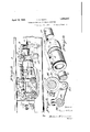
In the drawings Figure 1 is a plan view of the parts beneath a portion of the cloth plate showing the looper mechanism and the means for imparting oscillating` motions to the looper..
F ig. 2 is a View partly in front elevation and partly in section of the looper operating mechanism.
f ig. 3 is an enlarged sectional View on Jthe line 3 3 of F ig. 1.
Fig. 4 is a detached perspective View showing the sleeve for joining the ends of the shaft sections and also the eccentric formed integral therewith which impart-s oscillations to the looper.
The invention is directed to a looper operating mechanism for sewing machines and is shown as applied to a sewing machine having a supporting bed 1 carrying a cloth plate 2. Mounted for rotation in suitable bearings in the cloth plate is the main shaft which consists of two sections 3 and v4. The section 3 is the driven section and carries the usual crank or eccentric member for imparting vibrations to the needle lever. The section 4 operates the feed and imparts lateral or needle avoiding movements to the looper. The ends of the shaft sections 3 and 4 are joined Located in the keyways in the shaft sections and in the sleeve is a square key 6.7) which positively -gcins the shafts. Mounted on the coupling sleeve 5 and formed as an integral part thereof is a ball eccentric 8. The keyway 5a in the sleeve extends all the way through the connecting member supporting the eccentric and through the eccentric. Cooperating with this ball eccentric 8 is an ec` centric strap 9. The eccentric strap 9 engages a ball stud 10 carried by an arm 11 of a rock lever 12.V This rock lever 12 is mounted on a suitable supporting shaft carried by the bed of the machine. The rock lever also includes an arm 13 carrying a ball stud 14.
There are two loopers shown in the drawings which are indicated at 15 and 16. These two loopers are mounted on a. looper rocker 17 and are connected by a link 1.8. A link 19 is attached to the looper 15 and to the ball stud 14. This link 19 is made in sections and is adapted to be buckled in order to position the loopers for threading. This link which is capable of buckling forms no part of the present invention, but is shown, described and claimed in the application of Frederick F. Zeier and Clarence C. Smith` filed August 27, 192e, serial No. 302,229.
The looper rocker 17 is cscillated by means of an eccentric 2O mounted on the shaft section 4. An eccentric strap 21 cooperating with the eccentric engages a ball stud 22 carried by an arm 23 which is rigidly attached to the shaft 24 on which the looper rocker 17 is clamped.
The feed bar carrying the feed dog is indicated at 25 in the drawings. This feed bar is connected to a feed rocker 26. The feed rocker is oscillated by a link 27 cooperating with a crank on the end of the shaftsection 4.
From the above it will be apparent that the eccentric 8 is connected to the shaft sections 3 and l through the connection of the coupling sleeve to these shaft sections. The shaft section 3 passes through the eccentric. The coupling sleeve serves as the sole means for supporting the eccentric and forms a very rigid support therefor insuring its proper seating on the shaft sect-ions 3 and 4. By making the shaft in sections and coupling the same by the sleeve, it will be readily noted that the section 3 may be provided with a crank and suitably inserted in the bearings therefor, while the section el is also provided i ith a. crank and inserted in its supporting bearings. by an endwise motion. After the two shafts are in place they are joined by this coupling sleeve and the square key lying in the keyways will always secure the two shaft sections in a predetermined timed relation to each other. They will likewise secure the eccentric to the joined shaft sections in a predetermined time relation thereto. Through tlhis keyw'ay lne crank at the feed end of the main shaft and the crank at the needle operating end of the main shaft and also the eccentric for moving the looper into and out of the needle thread loops are all positiv-ely joined in a predetermined timed rela-tion to each other. T he assembling of the parts cannot disturb this timed relation.
It is obvious that minor changes in the details of construction and the arrangement of the parts may be made without departing from the spirit of the invention as set forth in the appended claims.
Having fully described my invention, what I claim as new and desire to secure by Letters Patent, is:
l. A looper mechanism for sewing machines comprising a sectional main actuating shaft, a coupling sleeve for joiningthe ends of said sectional shaft, means for securing said sleeve to the ends of said shaft sections for joining the same, an eccentric formed integral with said sleeve, and actuating devices operated by said eccentric for moving the looper into and out of the needle thread loops.
2. A looper mechanism for sewing machines comprising a sectional main actuating shaft, a coupling sleeve for joining the ends of said sectional shaft, means associated with said coupling sleeve and the ends of said shaft sections for securing said sections together in a. predetermined timed relation, an eccentric formed integral with said sleeve, and actuating devices operated by said eccentric for moving the looper into and out of the needle loops.
3. In a sewing machine, a sectional main actuating shaft, one of said sections carrying CLARENCE C. SMITH.
Priority Applications (1)
| Application Number | Priority Date | Filing Date | Title |
|---|---|---|---|
| US417170A US1854564A (en) | 1929-12-28 | 1929-12-28 | Looper mechanism for sewing machines |
Applications Claiming Priority (1)
| Application Number | Priority Date | Filing Date | Title |
|---|---|---|---|
| US417170A US1854564A (en) | 1929-12-28 | 1929-12-28 | Looper mechanism for sewing machines |
Publications (1)
| Publication Number | Publication Date |
|---|---|
| US1854564A true US1854564A (en) | 1932-04-19 |
Family
ID=23652858
Family Applications (1)
| Application Number | Title | Priority Date | Filing Date |
|---|---|---|---|
| US417170A Expired - Lifetime US1854564A (en) | 1929-12-28 | 1929-12-28 | Looper mechanism for sewing machines |
Country Status (1)
| Country | Link |
|---|---|
| US (1) | US1854564A (en) |
-
1929
- 1929-12-28 US US417170A patent/US1854564A/en not_active Expired - Lifetime
Similar Documents
| Publication | Publication Date | Title |
|---|---|---|
| US1854564A (en) | Looper mechanism for sewing machines | |
| US2669205A (en) | Work feeding mechanism for sewing machines | |
| US1450456A (en) | Feeding mechanism for sewing machines | |
| US1999893A (en) | Sewing machine | |
| US3583343A (en) | Sewing machine with top feed means | |
| US1929299A (en) | Feeding mechanism for flat bed machines | |
| US2029233A (en) | Looper mechanism for sewing machines | |
| US1773075A (en) | Sweing machine | |
| US1861540A (en) | Looper operating mechanism for sewing machines | |
| US1950337A (en) | Feeding mechanism for sewing machines | |
| US1737395A (en) | Needle-actuating mechanism for sewing machines | |
| US1973639A (en) | Sewing machine | |
| US885624A (en) | Sewing-machine. | |
| US591420A (en) | Union | |
| US1543946A (en) | Feeding mechanism for sewing machines | |
| US1200818A (en) | Needle-actuating mechanism for sewing-machines. | |
| US1257940A (en) | Looper mechanism for sewing-machines. | |
| US721082A (en) | Blindstitch sewing-machine. | |
| US591539A (en) | Union | |
| US1236599A (en) | Overseaming-machine. | |
| US461815A (en) | Sewing-machine | |
| US1243145A (en) | Looper mechanism for sewing-machines. | |
| US1841993A (en) | Sewing machine | |
| US1251474A (en) | Looper mechanism for sewing-machines. | |
| US1827577A (en) | Feed-off-the-arm sewing machine |