US1854534A - Floating roof for liquid storage tanks - Google Patents
Floating roof for liquid storage tanks Download PDFInfo
- Publication number
- US1854534A US1854534A US436482A US43648230A US1854534A US 1854534 A US1854534 A US 1854534A US 436482 A US436482 A US 436482A US 43648230 A US43648230 A US 43648230A US 1854534 A US1854534 A US 1854534A
- Authority
- US
- United States
- Prior art keywords
- roof
- pontoon
- tank
- members
- liquid storage
- Prior art date
- Legal status (The legal status is an assumption and is not a legal conclusion. Google has not performed a legal analysis and makes no representation as to the accuracy of the status listed.)
- Expired - Lifetime
Links
- 239000007788 liquid Substances 0.000 title description 23
- 239000002184 metal Substances 0.000 description 7
- 230000002093 peripheral effect Effects 0.000 description 6
- XLYOFNOQVPJJNP-UHFFFAOYSA-N water Substances O XLYOFNOQVPJJNP-UHFFFAOYSA-N 0.000 description 6
- 238000004519 manufacturing process Methods 0.000 description 5
- 239000007789 gas Substances 0.000 description 4
- 230000002459 sustained effect Effects 0.000 description 3
- 238000005452 bending Methods 0.000 description 2
- NRTLIYOWLVMQBO-UHFFFAOYSA-N 5-chloro-1,3-dimethyl-N-(1,1,3-trimethyl-1,3-dihydro-2-benzofuran-4-yl)pyrazole-4-carboxamide Chemical compound C=12C(C)OC(C)(C)C2=CC=CC=1NC(=O)C=1C(C)=NN(C)C=1Cl NRTLIYOWLVMQBO-UHFFFAOYSA-N 0.000 description 1
- 241000905957 Channa melasoma Species 0.000 description 1
- 241000009298 Trigla lyra Species 0.000 description 1
- 241000364021 Tulsa Species 0.000 description 1
Images
Classifications
-
- B—PERFORMING OPERATIONS; TRANSPORTING
- B65—CONVEYING; PACKING; STORING; HANDLING THIN OR FILAMENTARY MATERIAL
- B65D—CONTAINERS FOR STORAGE OR TRANSPORT OF ARTICLES OR MATERIALS, e.g. BAGS, BARRELS, BOTTLES, BOXES, CANS, CARTONS, CRATES, DRUMS, JARS, TANKS, HOPPERS, FORWARDING CONTAINERS; ACCESSORIES, CLOSURES, OR FITTINGS THEREFOR; PACKAGING ELEMENTS; PACKAGES
- B65D88/00—Large containers
- B65D88/34—Large containers having floating covers, e.g. floating roofs or blankets
Definitions
- drain that is used to carry raln water/off the top side of the roof is of such design or con.
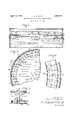
- Figure 1 of the drawings is a vertical trans-- verse sectional view of a liquid storage tank equipped with a floating roof embodying my present invention.
- Figure 2 is a fragmentary top plan view of said structure.
- - Figure 3 is an enlarged vertical sectional view of the roof drain.
- Figure 4 is a detail sectional view on an enlarged scale, taken on the line 4-4 of Figure l.
- A. designates the side wall of a liquid storage tank
- B designates a floating roof that normally rests upon and is sustained by the liquid in the tank.
- the roof B covers the major portion of the surface of the liquid in the tank, and the space between the pe- A of the tank is closed by an expansible and contractile structure, commonly referred to as a seal, that is provided with vertically- ⁇ disposed shoe members C that slide vertically 5 over the inner face of the side wall of the the pontoon D from metal plates that can ripheral edge of the roof andthe side wall tank when the roof B rises and falls, due to variations in the level of the liquid in the tank.
- the roof B herein shown is of the breather type, and is constructed of metal y plates connected together in such a way as to form-a limber sheet or diaphragm that is capable of flexing upwardly, as indicated in broken lines in Figure 1, ⁇ so as to increase the volume of the vapor space of the tank when n the roof is sustained by the liquid in the 6o tank.
- At the peripheral portion of the roof is an annular pontoon'D that floats onl the liquid in the tank and imparts buoyancy 'to the roof B.
- the pontoon D is so designed that the portion of the roof adjacent the inner edge of the pontoon will be held spaced slightly above the top surface of the liquid in the tank, thus providing a vaporspace or gas space for gases that rise from the liquid. If the pressure which the-gases or vapors exert upwardly on the under side 'of the central portion of the roof is -less hthan'the weight of said central portion, the central portion of the roof will deflect downwardly, as shown in full lines in Figure l, and when the pressure of the gases or vapors increases, the central portion of the roof will flex upwardly, as shown in broken lines in Figure l, therebyincreasing the volume of the vapor space.
- Floating roofs of the kind to which my invention relates .oftenV have a diameterl in excess of 100 ft. Accordingly, the fabrication and shipment of the circular pontoon for a large-sized roof is an item of considerable importance in the cost of manufacturing and ⁇ installing the roof.
- 011e object of my invention is to cut down this cost.
- the pontoon D is made up of two groups of L-shaped members or' plates 1 and 2 that constitute the bottom and side walls ofthe pontoonD, the top wall of the pontoon being formed preferably by the peripheral edge portion ofthe roof'B. 10
- the L-shaped mem ⁇ bers 1 constitute the outer side wall and a portion of the bottom of the pontoon D
- the L-shaped members 2 constitute the inner side wall and a portion of the bottom of said pontoon.
- the members. 1 are arranged so that the edge portions of the verticalv flanges and the horizontal flanges arein overlapping relation, and the overlapped portions of said members are permanently connected together in any suitable way, but preferably by welded joints
- the inner group of members 2 are similarly arranged and connected together by welded joints, and the horizontal' flanges of the two groups of members 1 and 2 are overlapped and joined together by welded joints m or 'in any other suitable manner.
- the pontoon D is combined with the roof B, but I prefer to provide the vertical legs of the inner group of members 2 of the pontoon with laterallyprojecting flangesy 3 that are attached to the underside of the roof B in any preferred way and provide the roof B at its peripheral edge with an upwardly-projecting flange 4 (see Figure 1) that is attached in Aany/suitable or preferred manner to the vertical legs of the outer group of members lof the pontoon.
- the horizontal legs of the members 1 and 2 of the pontoon are tapered longitudinally slightly or are made: substantially wedgeshaped, and it will also be noted that the inner group of members 2 are narrower than the outer group of members. It ispossible to proportion the members 1 and 2 in this way, because the inner vertical wall of the pontoon is of less diameter than the outer vertical wall of the pontoon, and by constructing the pontoon in this way, I materially reduce the cost of manufacturing the same, due to the saving in metal effected by using narrower members 2 to form the inner portion of the pontoon.
- the members 1 and 2 are angle-shaped, or L-shaped in outline, they can be produced from fiat metal plates by a simple bending operation, and another advantage of such a design of pontoon is thatit permits pontoons of large and small'diameters-to; be fabricated Awith equal ease.
- the pontoon D While I prefer to construct the pontoon D from two concentric rows of L-shaped members Whose vertical legs constitute the side walls of the pontoon and whose horizontal legs constitute the horizontal wall of the pon- ⁇ toon, l wish it to be understood that my broad idea contemplates constructing the pontoon from members of other shapes or form, as my invention, broadly stated, consists of a floating roof provided with a pontoon having a ycircular portion (either Vertical or horizontal) made up of or comprising a plurality of flat or straight plate-like members whose edge portions are connected together in such a way that said plate-like members, taken collectively, constitute a circular portion of the pontoon.
- a ycircular portion either Vertical or horizontal
- lt is preferably that the edge portions of said plate-like members be overthat do not have to be curved or bent or cut ⁇ into segmental shape during the fabrication of the pontoon, and any floating roof pontoon that embodies this feature or characteristie should be considered as coming within thescope of my invention, even though' the members or elements that make up the principal portion of the pontoon are not of the particular shape and arrangement herein illustrated.
- Another desirable feature of such a pontoon is that the joints of same can bd caulked from the upper side, even though the roof is floating on the liquid.
- the drain that is used to conduct rain water off the top side of the roof B is preferably of the inverted siphon type, and is composed of a vertically-disposed pipe E attached to the center of the roof B, and depending from the underside of same, and a hollow member or cup F arranged horizontally at the lower end of ,the pipe E and having its bottom butting against'the lower end of the pipe E and secured tovsame in any suitable way, as, for example, by a welded joint m2.
- the lVater which collects on the top side of the central portion of the roof B will overflow from same downwardly through the pipe E, as indicated by the arrow in Figure 3, and will thence escape from said piper into the cup F through ports 5 in the lower end of said pipe, said water finally escaping from the cup F through an ⁇ opening 6 in the top of same, and thence flowing downwardly towards the bottom of the tank.
- the liquid confined in the tank 1s oil the rain Water that escapes from the top/13o side of the roof through the drain pipe E will collect in a layer on the bottom of the tank, from which point said rain water can be dis charged through an outlet in the side wall of vthe tank, as is common practicein oil storage tanks.
- the vcup F may vary 1n shape and dated February 23, 1926.
- the drain formed by the pipe E and cup F, is used as a support for the central portion of the roof B when the,y
- the tank isy empty, and the roof is arranged at the lower end of the tank, as shown in broken lines in Figure 1.
- the pontoon D rests upon the bottom of the tank, thus sustaining the load of the peripheral portion of the roof, and the drain sustainsfthe load of the' central portion of the roof.
- the cup F of the drain serves as a foot piece for the drain pipe E that has a relatively large bearing area on the bottom of the tank, andthe pipe E is made long enough to produce a safe drain of the inverted siphon typ'evwhose long leg is of sufficient length to eliminate the possibility of the oil in the tank escaping upwardly through the pipe E.
- a floating roof embodying my present invention it is not necessary to equip the roof with depending legs or similar devices whose sole function is to sustain the weight of the roof when the tank is empty, because in my improved roof the pontoon D which is used to impart buoyancy to the roof and the drain pipe E which is used to conduct water olf the top side of the roof, co-act with each other to support the roof and hold it spaced away from the bottom of' the,l tank when the tank is empty.
- a floating roof for liquid storage tanks provided with a vpontoon having a vertical wall of circular form made up of a plurality ⁇ of fiat or straight metal plates whose vertical edge portionsare lapped and joined together,
- a floating roofl for liquid storage tanks provided with a circular pontoon-having a horizontal portion and vertical side 'walls made up of substantially L-shaped members joined together.
- a floating roof for liquid storage tanks provided with a .circular pontoon having a vhorizontal portion and vertical side walls made up of substantially L-shaped members arranged in overlapping relation and joined together.
- a floating roof for liquid storage tanks provided w ith, a circular pontoon that comprises two concentric rows of L-shaped members arranged with their edge portions over lapped'ff'cfv 6.
- a floating roof for liquid storage tanks provided with a circular pontoon that comprises two'concentric rows of L-shaped memers arranged with their edge portions overlapped, the members of the respective rows also being overlapped.
- a floating roof for liquid storage tanks provided with a circular pontoon made up principally of L-shaped members whose horizontal legs are tapered or substantially wedge-shaped.
- a floating roof for liquid storage tanks provided with a circular pontoon that comprises an inner row and an outer row of flanged metal plates, the plates of the inner row being of smaller circumferential dimension than the plates'of the outer row.
- a floating roof for liquid storage tanks and an annular pontoon at the peripheral edge ofA the roof whose top wall is formed by the roof and whose side walls and bottom wall are formed from substantially L-shaped members arranged in opposed relation in two concentric rows.
- a floating rooffor liquid storage tanks, and an annular pontoon at the peripheral edge of the roof whose top wall is formed by the roof and whose side walls and bottom wall are formed from substantially L-shaped members arranged in opposed relation in two concentric rows, with the members constituting each row disposed in overlapping relation and with the horizontal legs of the members of the respective rows disposed in overlapping relation.
Landscapes
- Engineering & Computer Science (AREA)
- Mechanical Engineering (AREA)
- Filling Or Discharging Of Gas Storage Vessels (AREA)
Description
April 19, 1932. J. H. WIGGINS FLOATING ROOF FOR LTQUTD STORAGE TANKS Filed March 17, i930 4T' To few/wijf Patented Apr. 19, 1932 STATES s .l i JOHN E. WIGGINS, F TULSA, OKLAHOMA FLOATING ROOF FOR LIQUID STORAGE TANKS Application led March '17, 1930. Serial No. 436,482.
drain that is used to carry raln water/off the top side of the roof is of such design or con.
struction that it serves as a support which holds the central portion of the roof in spaced relation with the bottom of the`tank when the tank isempty and the load of the roof is sustained by the bottom of the tank.
And .still another obj ect is to eliminate the necessity of forming a well in the bottom of a liquid storage tank. equipped with a floating roof provided with a drain of the inverted siphon type. Other objects and desirable features of my invention will be hereinafter pointed out.
Figure 1 of the drawings is a vertical trans-- verse sectional view of a liquid storage tank equipped with a floating roof embodying my present invention. j
Figure 2 is a fragmentary top plan view of said structure. A
-Figure 3 is an enlarged vertical sectional view of the roof drain; and
Figure 4 is a detail sectional view on an enlarged scale, taken on the line 4-4 of Figure l.
In the accompanying drawings which illustrate the preferred form of my invention, A. designates the side wall of a liquid storage tank, and B designates a floating roof that normally rests upon and is sustained by the liquid in the tank. The roof B covers the major portion of the surface of the liquid in the tank, and the space between the pe- A of the tank is closed by an expansible and contractile structure, commonly referred to as a seal, that is provided with vertically-` disposed shoe members C that slide vertically 5 over the inner face of the side wall of the the pontoon D from metal plates that can ripheral edge of the roof andthe side wall tank when the roof B rises and falls, due to variations in the level of the liquid in the tank. The roof B herein shown is of the breather type, and is constructed of metal y plates connected together in such a way as to form-a limber sheet or diaphragm that is capable of flexing upwardly, as indicated in broken lines in Figure 1,\so as to increase the volume of the vapor space of the tank when n the roof is sustained by the liquid in the 6o tank. At the peripheral portion of the roof is an annular pontoon'D that floats onl the liquid in the tank and imparts buoyancy 'to the roof B. In the roof herein shown the pontoon D is so designed that the portion of the roof adjacent the inner edge of the pontoon will be held spaced slightly above the top surface of the liquid in the tank, thus providing a vaporspace or gas space for gases that rise from the liquid. If the pressure which the-gases or vapors exert upwardly on the under side 'of the central portion of the roof is -less hthan'the weight of said central portion, the central portion of the roof will deflect downwardly, as shown in full lines in Figure l, and when the pressure of the gases or vapors increases, the central portion of the roof will flex upwardly, as shown in broken lines in Figure l, therebyincreasing the volume of the vapor space.
Floating roofs of the kind to which my invention relates .oftenV have a diameterl in excess of 100 ft. Accordingly, the fabrication and shipment of the circular pontoon for a large-sized roof is an item of considerable importance in the cost of manufacturing and` installing the roof.
011e object of my invention is to cut down this cost. To this end l propose to construct be shaped easily by a simple bending operation and which can be shipped in nested relation from the point of manu/facture tothe place of use. In the form of my invention herein illustrated the pontoon D is made up of two groups of L-shaped members or' plates 1 and 2 that constitute the bottom and side walls ofthe pontoonD, the top wall of the pontoon being formed preferably by the peripheral edge portion ofthe roof'B. 10
As shown in Figure 4, the L-shaped mem\ bers 1 constitute the outer side wall and a portion of the bottom of the pontoon D, and the L-shaped members 2 constitute the inner side wall and a portion of the bottom of said pontoon.. AThe members. 1 are arranged so that the edge portions of the verticalv flanges and the horizontal flanges arein overlapping relation, and the overlapped portions of said members are permanently connected together in any suitable way, but preferably by welded joints The inner group of members 2 are similarly arranged and connected together by welded joints, and the horizontal' flanges of the two groups of members 1 and 2 are overlapped and joined together by welded joints m or 'in any other suitable manner. Itis immaterial how the pontoon D is combined with the roof B, but I prefer to provide the vertical legs of the inner group of members 2 of the pontoon with laterallyprojecting flangesy 3 that are attached to the underside of the roof B in any preferred way and provide the roof B at its peripheral edge with an upwardly-projecting flange 4 (see Figure 1) that is attached in Aany/suitable or preferred manner to the vertical legs of the outer group of members lof the pontoon.
By referring to Figure 4 it will be `seen that the horizontal legs of the members 1 and 2 of the pontoon are tapered longitudinally slightly or are made: substantially wedgeshaped, and it will also be noted that the inner group of members 2 are narrower than the outer group of members. It ispossible to proportion the members 1 and 2 in this way, because the inner vertical wall of the pontoon is of less diameter than the outer vertical wall of the pontoon, and by constructing the pontoon in this way, I materially reduce the cost of manufacturing the same, due to the saving in metal effected by using narrower members 2 to form the inner portion of the pontoon. As the members 1 and 2 are angle-shaped, or L-shaped in outline, they can be produced from fiat metal plates by a simple bending operation, and another advantage of such a design of pontoon is thatit permits pontoons of large and small'diameters-to; be fabricated Awith equal ease. In shipping the roof from the place where the parts of same are shaped or formed to the place Where the roof is installed in a tank,`
used in the seal of the roof, as this is advantageous in the fabrication of the roof.
While I prefer to construct the pontoon D from two concentric rows of L-shaped members Whose vertical legs constitute the side walls of the pontoon and whose horizontal legs constitute the horizontal wall of the pon- `toon, l wish it to be understood that my broad idea contemplates constructing the pontoon from members of other shapes or form, as my invention, broadly stated, consists of a floating roof provided with a pontoon having a ycircular portion (either Vertical or horizontal) made up of or comprising a plurality of flat or straight plate-like members whose edge portions are connected together in such a way that said plate-like members, taken collectively, constitute a circular portion of the pontoon. lt is preferably that the edge portions of said plate-like members be overthat do not have to be curved or bent or cut` into segmental shape during the fabrication of the pontoon, and any floating roof pontoon that embodies this feature or characteristie should be considered as coming within thescope of my invention, even though' the members or elements that make up the principal portion of the pontoon are not of the particular shape and arrangement herein illustrated. Another desirable feature of such a pontoon is that the joints of same can bd caulked from the upper side, even though the roof is floating on the liquid.
The drain that is used to conduct rain water off the top side of the roof B is preferably of the inverted siphon type, and is composed of a vertically-disposed pipe E attached to the center of the roof B, and depending from the underside of same, and a hollow member or cup F arranged horizontally at the lower end of ,the pipe E and having its bottom butting against'the lower end of the pipe E and secured tovsame in any suitable way, as, for example, by a welded joint m2. lVater which collects on the top side of the central portion of the roof B will overflow from same downwardly through the pipe E, as indicated by the arrow inFigure 3, and will thence escape from said piper into the cup F through ports 5 in the lower end of said pipe, said water finally escaping from the cup F through an `opening 6 in the top of same, and thence flowing downwardly towards the bottom of the tank. If the liquid confined in the tank 1s oil, the rain Water that escapes from the top/13o side of the roof through the drain pipe E will collect in a layer on the bottom of the tank, from which point said rain water can be dis charged through an outlet in the side wall of vthe tank, as is common practicein oil storage tanks. The vcup F may vary 1n shape and dated February 23, 1926.
In the roof herein shown the drain, formed by the pipe E and cup F, is used as a support for the central portion of the roof B when the,y
tank isy empty, and the roof is arranged at the lower end of the tank, as shown in broken lines in Figure 1. At such times the pontoon D rests upon the bottom of the tank, thus sustaining the load of the peripheral portion of the roof, and the drain sustainsfthe load of the' central portion of the roof. The cup F of the drain serves as a foot piece for the drain pipe E that has a relatively large bearing area on the bottom of the tank, andthe pipe E is made long enough to produce a safe drain of the inverted siphon typ'evwhose long leg is of sufficient length to eliminate the possibility of the oil in the tank escaping upwardly through the pipe E. Notwithstanding the relatively great 'length of the drain pipe E, it is not necessary to form a vertical well in the bottom of the tank to receive the drain when the tank is empty or substantially so, due to the fact that the central portion of the roofl to which the drain is attached has sufficient 'flexibility to permit the central portion of the roof to flex upwardly, as indicated in broken lines at the lower end of Figure 1, whenthe pontoon D rests upon the bottom of the tank. Hence, in a floating roof embodying my present invention it is not necessary to equip the roof with depending legs or similar devices whose sole function is to sustain the weight of the roof when the tank is empty, because in my improved roof the pontoon D which is used to impart buoyancy to the roof and the drain pipe E which is used to conduct water olf the top side of the roof, co-act with each other to support the roof and hold it spaced away from the bottom of' the,l tank when the tank is empty.
lof flat or straight metal plates whose vertical edge portions are lapped and joined together, said plates having lateral extensions that constitute a horizontal portion 'of the pontoon. l, f 2. A floating roof for liquid storage tanks, provided with a vpontoon having a vertical wall of circular form made up of a plurality` of fiat or straight metal plates whose vertical edge portionsare lapped and joined together,
said plates having laterally-projectingflanges that are overlapped and connected together so as to form a horizontal portion of the pontoon. v
3. A floating roofl for liquid storage tanks, provided with a circular pontoon-having a horizontal portion and vertical side 'walls made up of substantially L-shaped members joined together.
4. A floating roof for liquid storage tanks, provided with a .circular pontoon having a vhorizontal portion and vertical side walls made up of substantially L-shaped members arranged in overlapping relation and joined together.
5. A floating roof for liquid storage tanks, provided w ith,a circular pontoon that comprises two concentric rows of L-shaped members arranged with their edge portions over lapped'ff'cfv 6. A floating roof for liquid storage tanks, provided with a circular pontoon that comprises two'concentric rows of L-shaped memers arranged with their edge portions overlapped, the members of the respective rows also being overlapped.
7. A floating roof for liquid storage tanks, provided with a circular pontoon made up principally of L-shaped members whose horizontal legs are tapered or substantially wedge-shaped. f Y
8. A floating roof for liquid storage tanks, provided with a circular pontoon that comprises an inner row and an outer row of flanged metal plates, the plates of the inner row being of smaller circumferential dimension than the plates'of the outer row.'
9. A floating roof for liquid storage tanks, and an annular pontoon at the peripheral edge ofA the roof whose top wall is formed by the roof and whose side walls and bottom wall are formed from substantially L-shaped members arranged in opposed relation in two concentric rows.
10. A floating rooffor liquid storage tanks, and an annular pontoon at the peripheral edge of the roof whose top wall is formed by the roof and whose side walls and bottom wall are formed from substantially L-shaped members arranged in opposed relation in two concentric rows, with the members constituting each row disposed in overlapping relation and with the horizontal legs of the members of the respective rows disposed in overlapping relation.
JOHN H. WIGGINS.
lll
Priority Applications (1)
| Application Number | Priority Date | Filing Date | Title |
|---|---|---|---|
| US436482A US1854534A (en) | 1930-03-17 | 1930-03-17 | Floating roof for liquid storage tanks |
Applications Claiming Priority (1)
| Application Number | Priority Date | Filing Date | Title |
|---|---|---|---|
| US436482A US1854534A (en) | 1930-03-17 | 1930-03-17 | Floating roof for liquid storage tanks |
Publications (1)
| Publication Number | Publication Date |
|---|---|
| US1854534A true US1854534A (en) | 1932-04-19 |
Family
ID=23732576
Family Applications (1)
| Application Number | Title | Priority Date | Filing Date |
|---|---|---|---|
| US436482A Expired - Lifetime US1854534A (en) | 1930-03-17 | 1930-03-17 | Floating roof for liquid storage tanks |
Country Status (1)
| Country | Link |
|---|---|
| US (1) | US1854534A (en) |
Cited By (3)
| Publication number | Priority date | Publication date | Assignee | Title |
|---|---|---|---|---|
| DE1039940B (en) * | 1957-07-11 | 1958-09-25 | John Henry Wiggins | Floating lid of a liquid high container |
| US2931534A (en) * | 1958-04-07 | 1960-04-05 | John H Wiggins | Automatic emergency drain mechanisms for floating roofs |
| US11548725B2 (en) | 2013-03-15 | 2023-01-10 | Industrial & Environmental Concepts, Inc. | Cover systems, tank covering methods, and pipe retention systems |
-
1930
- 1930-03-17 US US436482A patent/US1854534A/en not_active Expired - Lifetime
Cited By (3)
| Publication number | Priority date | Publication date | Assignee | Title |
|---|---|---|---|---|
| DE1039940B (en) * | 1957-07-11 | 1958-09-25 | John Henry Wiggins | Floating lid of a liquid high container |
| US2931534A (en) * | 1958-04-07 | 1960-04-05 | John H Wiggins | Automatic emergency drain mechanisms for floating roofs |
| US11548725B2 (en) | 2013-03-15 | 2023-01-10 | Industrial & Environmental Concepts, Inc. | Cover systems, tank covering methods, and pipe retention systems |
Similar Documents
| Publication | Publication Date | Title |
|---|---|---|
| US1819401A (en) | Floating roof | |
| US2321058A (en) | Floating roof for liquid storage tanks | |
| US2359416A (en) | Liquid storage tank | |
| US1493091A (en) | Floating deck | |
| US1735461A (en) | Method and means for sealing floating roofs | |
| US1854534A (en) | Floating roof for liquid storage tanks | |
| US1463268A (en) | Fireproof tank | |
| US1574013A (en) | Floating deck for liquid-storage tanks | |
| US2497047A (en) | Center-weighted floating roof | |
| NO125226B (en) | ||
| US1904339A (en) | Floating deck for liquid storage tanks | |
| US1666415A (en) | Floating deck or cover for oil tanks | |
| US1903291A (en) | Floating deck | |
| US1909484A (en) | Liquid storage reservoir | |
| US1777560A (en) | Floating deck | |
| US3647113A (en) | Floating roof for liquid storage tanks, particularly for the storage of liquid petroleum products | |
| US1716491A (en) | Floating deck, gas-tight type | |
| US2516101A (en) | Liquid seal for floating roofs | |
| US1893162A (en) | Sealing means for floating roofs for tanks | |
| US2461763A (en) | Tank roof | |
| US2070828A (en) | Floating deck for tanks | |
| US1989624A (en) | Floating roof for storage tanks | |
| US1514116A (en) | Oil-storage tank | |
| US1992221A (en) | Multiple seal floating deck tank | |
| US1928640A (en) | Container |