US1854520A - Aircraft - Google Patents
Aircraft Download PDFInfo
- Publication number
- US1854520A US1854520A US486884A US48688430A US1854520A US 1854520 A US1854520 A US 1854520A US 486884 A US486884 A US 486884A US 48688430 A US48688430 A US 48688430A US 1854520 A US1854520 A US 1854520A
- Authority
- US
- United States
- Prior art keywords
- rotors
- fuselage
- aircraft
- shaft
- pair
- Prior art date
- Legal status (The legal status is an assumption and is not a legal conclusion. Google has not performed a legal analysis and makes no representation as to the accuracy of the status listed.)
- Expired - Lifetime
Links
- 230000000694 effects Effects 0.000 description 5
- NWUMSRKLBRWRAS-UHFFFAOYSA-N Arundoin Natural products COC1CCC2(C)C(CCC3C2=CCC4(C)C5CC(C)(C)CCC5(C)CCC34C)C1(C)C NWUMSRKLBRWRAS-UHFFFAOYSA-N 0.000 description 1
- MRNPHCMRIQYRFU-UWAWSDATSA-N Cylindrin Chemical compound C([C@@]1(C)[C@H](C(C)C)CC[C@@H]1[C@@]1(C)CC=C23)C[C@@]1(C)[C@@H]3CC[C@@H]1[C@]2(C)CC[C@H](OC)C1(C)C MRNPHCMRIQYRFU-UWAWSDATSA-N 0.000 description 1
- BRQBMPGDACUHNR-UHFFFAOYSA-N Cylindrin Natural products COC1CCC2(C)C(CCC3C2=CCC4(C)C5CCC(C(C)C)C5CCC34C)C1(C)C BRQBMPGDACUHNR-UHFFFAOYSA-N 0.000 description 1
- 101100001674 Emericella variicolor andI gene Proteins 0.000 description 1
- 238000007664 blowing Methods 0.000 description 1
- 238000004891 communication Methods 0.000 description 1
- 238000010276 construction Methods 0.000 description 1
- 108010089310 cylindrin Proteins 0.000 description 1
- 238000012986 modification Methods 0.000 description 1
- 230000004048 modification Effects 0.000 description 1
- 230000000630 rising effect Effects 0.000 description 1
- 238000007789 sealing Methods 0.000 description 1
Images


Classifications
-
- B—PERFORMING OPERATIONS; TRANSPORTING
- B64—AIRCRAFT; AVIATION; COSMONAUTICS
- B64C—AEROPLANES; HELICOPTERS
- B64C23/00—Influencing air flow over aircraft surfaces, not otherwise provided for
- B64C23/08—Influencing air flow over aircraft surfaces, not otherwise provided for using Magnus effect
Definitions
- the present invention relates to aircraft in general and more particularly to heavierthan-air machines of the plane or wing type.
- the main object of the invention is to provide such machines with an arrangement of apparatus or devices which, independently of, or in cooperation with, the propelling means of the machine, facilitates the ascent or descent of the machine.
- the object of the present invention is to provide an improved arrangement so that the aircraft may rise or ascend from the ground or from any level to any other desired level in a much shortened linear range.
- the same apparatus is, of course,
- the present invention also comprehends apparatus of the type above described and provided with means whereby its effect during normal Hight is minimized or entirely eliminated.
- the present invention is in part directed to apparatus and devices for moving the lifting arrangement from its operative to its inoperative position and also for moving the same in the reverse direction, whether the plane be in Hight or on the ground.
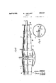
- Figure l is a side view of an aircraft embodying the preferred form of the invention.
- Figure 2 is a plan view of the stream line bar carrying the rotors
- Figure 3 is a sectional view, taken on the line 3 3 of Figure 4, of one of the rotor sections showing the manner in which it is supported and carried by the bar;
- Figure 4 is a sectional view taken on line 4-4-4 of Figure l with the rotors shown in 1 their extended or effective positions;
- Figure 5 is a View similar to Figure 4 with the rotors shown in their collapsed positions;
- Figure 6 is a partial sectional view taken upon line 6-6 of Figure 4.
- Figure 7 is a sectional view taken on line 7 7 of Figure 6;
- Figure 8 shows a modified form of the invention
- Figure 9 shows a modified form of the rotor carrying bar in the form of an airfoil.
- the present invention relates broadly to aircraft and to apparatus which is designed to utilize the Magnus effect to assist in the rising or landing of such aircraft or generally inv ascents or descents of such aircraft so that such operations may be accomplished at 100 very sharp angles which may perhaps approach the vertical.
- the present invention relates to the employment of a pair of rotatable rotors which extend laterally from the fuselage or any part of the airplane Where they can be conveniently Carried, housed and operated, the rotors being rotated along the horizontal axis at a speed under the control of the pilot.
- the rotation of such rotors cooperates with air currents blowing in a direction at right angles to the axis of the cylinders to bring about a reaction which is effective upon the rotors along a line upward and rearward at an angle to the direction of the aircurrent.
- the air current created by the ⁇ propeller is utilized to cooperate with the rotation of the cylinders to obtain the desired effect in the ldesired direction.
- the preferred form of the invention illustrated therein is shown as embodied and applied toan aircraft of the monoplane type and comprising a fuselage 10 and a pair of wings 11.
- a stream line pair of bars 12 are carried by the rotatable shaft 13 .the same being rotatably supported within the fuselage by the frame 14 and the bearing 15.
- the bars 12 Vare preferably made to rotate with the shaft 13 by means of the cross-pins l16.
- the shaft 13 is preferably provided -witha sprocket wheel 17 so that power may be transmitted to the same to rotate the bars 12 and rotor Vcylinders when the same are put into their effective positions.
- 18 shows a motor of any suitabletype housed Within the fuselage and which may be utilized for rotating the airfoils 12, it being understood, however, that if desired the same may be rotated by the propeller motor 19.
- the shaft 13 preferably projects beyond the front ends of the bars 12, as is shown in Figure 2, .these ends being rotatably carried by journals 2() which are. supported and carried by the strut structures 21 carried by the wings 11.
- the side walls .of the fuselage are provided with circular openings and arcuate plates 22 and 23 are disposed between the side walls of the fuselage and immediately adj acent the openings therein but slightly spaced therefrom. These plates 22 .and 23 serve as guides lfor the movement of the rotors. 24 and Each of the rotors 24 .and 25 consist-s of a series of telescoping cylindrical sections.
- each section 26 has an exterior diameter substantially equal to the openings in the side walls of the fuselage and are provided at their inner ends with exterior flanges 27 which may be made to slide within the arcuate guide plates 22 and 23 and which in the extended positions of the rotors 24 and 25 abut the inner face of the side walls of the fuselage.
- the outer end of each section 26 is provided with an inturned flange 31.
- Each succeeding section of which there may be as many as desired, such as the sections 28, 29, and 30, are somewhat smaller in diameter than each preceding section and are similarly provided with outward flanges 32 vat their inner ends and with inturned flanges 33 at their outer ends which cooperate with the corresponding flange of the adjacent section to'apermit ofthe ready expansion and collapse of the series of sections.
- the end section has its outerend closed by the wall 34 and which is provided with an opening of the same shape as the bar 12.
- the inner end of each section is additionally provided with a pair of inwardly projecting and suitably shaped guide lugs 35 which ride on the forward and rear edges of the 1bar 12.
- the engagement between the edges Vof .the bars 12 and the lugs 35 is such, as will be seen in Figure 6, that the rotation of the shaft 13 and of the bar 12 therewith will also bring about the rotation of all of the sections of the rotors 24 and 25.
- the end wall 34 yof the outermost cylindrin cal section 30 is preferably provided with an outward annular flange 36 which. is engaged to extend and collapse the rotors as hereinaft-er described, this flange 36 serving also the additional function of preventing the Vair from spilling off the ends of the rotors when the same are yin operation.
- the presentinvention also contemplates the provision of apparatus kand devices under the control of the airplane operator for the movement ofthe rotors 24 and 25 from their collapsed position shown in Figure 5 to their extended or effective position shown in Figure 4, or in the reverse direction.
- This apparat-us comprises a worm 37 rotatably mounted in bracket 38, the worm being provided with a hand wheel 39 for the manual operation of the same in either direction or a motor may be provided for the operation of this worm.
- the worm wheel 40 engaging the worm 37 and rotatably supported by brackets 41 and 42 carries on its shaft 43 a sprocket wheel 44, the latter being connected vices the drum 48 may be rotated in one direction or the other.
- a pair of cables 51 and 52 are partially wound on the drum 48, the cable 51 being designed to operate the rotor 24 and the cable 52 being designed to operate the rotor 25. Each of these cables pass around pulleys 65 and 65a carried by the plate 22.
- the cable 51 passing around this pulley is connected at one end to the lug 53 of an element 53a having a groove 53?) in which the plate 36 associated With the rotor 24 engages.
- the other end of the cable 51 is connected to the eye 54 disposed on the opposite face of the elements 53a.
- This second yend of the cable 51 passes from the eye 54 around the guide pulley 55 carried by one of the struts 21 and thence over the guide pulley 56 and back to the drum 48.
- the cable 52 is connected to the eye 53 on the element 53a and the other end of the cable is connected to the eye 54 and then passes around guide pulleys 55 and 56 and back to the drum 48.
- the pairs of eyes 53 and 54 and 53 and 54 respectively are carried by the elements 53a and 53a and the flanges 36 engage in the grooves 536 and 535 to permit the free rotation of the plate 36.
- FIG. 8 shows a form of the invention which obviates the use of cables for projecting or collapsing the roto-rs, this being accomplished by means of air pressure to extend or project the rotors and by means of exhaust to collapse the same.
- the T-pipe 60 is connected to the interior of the rotors, this pipe being connected to a pump (not shown) so that when it is desired to expand or project the rotors the air under pressure is caused to enter the rotors and when it is desired to collapse the same the pump is operated to exhaust the air from the interior of the cylinders, thereby subjecting the cylinders to atmospheric pressure which causes their collapse.
- guide plates 22 and 23 are replaced by a hermetically sealed cylinder 61, the same being interiorly divided by means of the walls 62 and 63.
- each rotor forms, together' with the corresponding chamber of the cylinder 6l, a hermetically sealed interior in communication with the pipe 60. This obviates the use of cables.
- Figure 8 may be combined with the other figures shownherein will be apparent' to persons skilled in the art.
- Figure 9 illustrates a modified form of the bar in the form of an airfoil 64 which may be used in lieu of the stream line bar 12 shown ⁇ in the remaining figures.
- ySuitable means may bel provided to indicate to the pilot when the bar 12 or airfoil is in the most efficient position for flying after the rotors have been collapsed.
- v Y Y J In an aircraft, a structural body, a pair of wings, a pair of revoluble sustaining elements, one on each side of the structural body, means for rotating said sustaining ele ⁇ ments, said elements being normally disposed interiorly of the structural body, and ⁇ means for projecting the same outwardly from the structural body to effective position.
- a structural body In an aircraft, a structural body, a pair of wings, a pair of revoluble sustaining elements, one on each side of the structural body, each comprising a series of telescopically collapsible cylindrical sections, means for rotating said sustaining elements, said elements being normally disposed interiorly of the structural body, and means for projecting the same outwardly from the structural body to effective, position.
- a structural body In an aircraft, a structural body, a pair of wings, a pair of revoluble sustaining elements, one on yeach side of the structural body, said elements being soconstructed and arranged that the same may be collapsed to a position interiorly of the structural body, or projectedy to a position exteriorly of the structuralk body, and means for moving the same from one position to the other.
- afuselage a pair of wings carried by saidv fuselage, a shaft-disposed transversely of said fuselage and ex tending exteriorly thereof, means for'rotating said shaft, a pair of revoluble sustaining elements, one on each side of said fuselage carried by said shaft, said sustaining elements each comprising a series'of telescopically collapsible and expansible cylindrical sections, and pneumatic means for moving these sustaining elements from collapsed to extended positions.
- a fuselage In an aircraft, a fuselage, a pair of wings carried by said fuselage, a shaft disposed transversely of said fuselage and extending exteriorly thereof, a bearing for each of the free ends of said shaft, struts carried by said wings supporting said bearings, means for rotating said shaft, a pair of revoluble sustaining elements, one on each side of said fuselage carried by said airfoil, said sustaining amen-ts each comprising a. series of telescopically collapsible'v and expansible cylindrical sections, andI meansy for' moving these sustaining elements. from collapsed to extended positions. l
- a structural body a shaft disposed trlnsversely of said structural body andfextending exteriorly thereof, a bearing foreach of the free ends of said shaft, struts supporting said bearings,.means for rotating said shaft,y an airfoil carried by said shaft, a pair of revoluble sustaining elements, one on eachside of said structural body carried by said airfoil', said sustaining elements eachv being constructed and arranged that the same f may be collapsed tol a position interiorly of' the structural body and projected to a position exteriorly of the structural body.
- a fuselage a shaft disposed transversely of said fuselage and eX- tending exteriorly thereof, a bearing for each of the free ends of said shaft, struts supporting said bearings, means for rotating said shaft, a; pair of revoluble sustaining elements, one on euch side of said fuselage carried by aid shaft, said sustaining elements cach being constructed and arranged that the same may-be collapsed to a position interiorly of the fuselage and projected to a position exteriorly of the fuselage.
- a structural body disposed interiorly of the structural body and transversely thereof, a pair of revoluble sustaining elements normally disposed within said chamber in collapsed position and sealing said chamber, each of said elements comprising a series of telescoping hollow cylindrical sections, and pneumatic means for moving said elements from collapsed to extended positions.
Landscapes
- Engineering & Computer Science (AREA)
- Aviation & Aerospace Engineering (AREA)
- Toys (AREA)
Description
April 19, 1932.
N. v.1. MEDvEDz-:FF
AIRCRAFT Filed Oct. 7', 1930 4 Sheets-Sheet' l April-19, 1932- N. J. MEDVEDEFF AIRCRAFT 4 sheets-sheet 2 Filed oct. fr, 195o April 19, 1932. N. J. MEDVEDEFF AIRCRAFT 4 Sheets-Sheet 4 Filed Oct. 7, 1930 INVENTOR /V/c/ro/as J//edvede//f BY M ATTORNEY:-
Patented Apr. 19, 1932 NICHOLAS J'. MEDVEDEFF, OF SCARSDALE, NEW YORK AIRCRAFT Application filed October 7, 1930. Serial No. 486,884.
The present invention relates to aircraft in general and more particularly to heavierthan-air machines of the plane or wing type. The main object of the invention is to provide such machines with an arrangement of apparatus or devices which, independently of, or in cooperation with, the propelling means of the machine, facilitates the ascent or descent of the machine.
More particularly the object of the present invention is to provide an improved arrangement so that the aircraft may rise or ascend from the ground or from any level to any other desired level in a much shortened linear range. The same apparatus is, of course,
employed for descending or landing with the same effect. Moreover, the devices being particularly useful during ascents and de- Y scents, it is frequently desirable to remove the effect of this apparatus during normal Hight. For this reason, therefore, the present invention also comprehends apparatus of the type above described and provided with means whereby its effect during normal Hight is minimized or entirely eliminated. For this purpose the present invention is in part directed to apparatus and devices for moving the lifting arrangement from its operative to its inoperative position and also for moving the same in the reverse direction, whether the plane be in Hight or on the ground. f f
Reference is hereby made'to my copending applications bearing the following lseria numbers; 470,409; 472.545; and ity will be apparent that features disclosed in the above mentioned copending applications may be embodied in an airplane embodying the subject matter of the present .application and it 5 ment of the invention by constructing the rowill also be apparent that the features distors in the form of a series of telescopic cylinders; which in normal Hight are preferably housed within thev airplane structure and which, when it is desired to ascend or descend, maybe operated to their effective positions; means also being provided for collapsing lcylinders or rotor sections within each other while in normal Hight.
l/Vith these and various other objects in View, the invention'consists in certain novel 60 features of construction andin combinations and arrangements more fully and particularly set forthihereinafter and more fully and clearly disclosed in the drawings constit-uting a part of the present application; it being understood, however, that the drawings taken together with'the lspecification submitted herewith'are' only illustrative of the invention and that modifications thereof, falling within the scope of the appended claims will be apparent to persons skilled in the art.
In the drawings: Figure l is a side view of an aircraft embodying the preferred form of the invention;
Figure 2 is a plan view of the stream line bar carrying the rotors;
Figure 3 is a sectional view, taken on the line 3 3 of Figure 4, of one of the rotor sections showing the manner in which it is supported and carried by the bar;
Figure 4 is a sectional view taken on line 4-4-4 of Figure l with the rotors shown in 1 their extended or effective positions;
Figure 5 is a View similar to Figure 4 with the rotors shown in their collapsed positions;
Figure 6 is a partial sectional view taken upon line 6-6 of Figure 4;
Figure 7 is a sectional view taken on line 7 7 of Figure 6;
Figure 8 shows a modified form of the invention; and
Figure 9 shows a modified form of the rotor carrying bar in the form of an airfoil.
rThe present invention relates broadly to aircraft and to apparatus which is designed to utilize the Magnus effect to assist in the rising or landing of such aircraft or generally inv ascents or descents of such aircraft so that such operations may be accomplished at 100 very sharp angles which may perhaps approach the vertical.
More particularly the present invention relates to the employment of a pair of rotatable rotors which extend laterally from the fuselage or any part of the airplane Where they can be conveniently Carried, housed and operated, the rotors being rotated along the horizontal axis at a speed under the control of the pilot. The rotation of such rotors cooperates with air currents blowing in a direction at right angles to the axis of the cylinders to bring about a reaction which is effective upon the rotors along a line upward and rearward at an angle to the direction of the aircurrent. While under some vconditions the air `currents existing in the `ambient atmosphere may be employed for that purpose, in the case of airplanes, the air current created by the` propeller is utilized to cooperate with the rotation of the cylinders to obtain the desired effect in the ldesired direction.
Referring to the drawings, the preferred form of the invention illustrated therein, is shown as embodied and applied toan aircraft of the monoplane type and comprising a fuselage 10 and a pair of wings 11. A stream line pair of bars 12 are carried by the rotatable shaft 13 .the same being rotatably supported within the fuselage by the frame 14 and the bearing 15. The bars 12 Vare preferably made to rotate with the shaft 13 by means of the cross-pins l16. The shaft 13 is preferably provided -witha sprocket wheel 17 so that power may be transmitted to the same to rotate the bars 12 and rotor Vcylinders when the same are put into their effective positions. 18 shows a motor of any suitabletype housed Within the fuselage and which may be utilized for rotating the airfoils 12, it being understood, however, that if desired the same may be rotated by the propeller motor 19.
The shaft 13 preferably projects beyond the front ends of the bars 12, as is shown in Figure 2, .these ends being rotatably carried by journals 2() which are. supported and carried by the strut structures 21 carried by the wings 11. The side walls .of the fuselage are provided with circular openings and arcuate plates 22 and 23 are disposed between the side walls of the fuselage and immediately adj acent the openings therein but slightly spaced therefrom. These plates 22 .and 23 serve as guides lfor the movement of the rotors. 24 and Each of the rotors 24 .and 25 consist-s of a series of telescoping cylindrical sections. For this purpose the sections 26 have an exterior diameter substantially equal to the openings in the side walls of the fuselage and are provided at their inner ends with exterior flanges 27 which may be made to slide within the arcuate guide plates 22 and 23 and which in the extended positions of the rotors 24 and 25 abut the inner face of the side walls of the fuselage. The outer end of each section 26 is provided with an inturned flange 31. Each succeeding section, of which there may be as many as desired, such as the sections 28, 29, and 30, are somewhat smaller in diameter than each preceding section and are similarly provided with outward flanges 32 vat their inner ends and with inturned flanges 33 at their outer ends which cooperate with the corresponding flange of the adjacent section to'apermit ofthe ready expansion and collapse of the series of sections.
The end section has its outerend closed by the wall 34 and which is provided with an opening of the same shape as the bar 12. The inner end of each section is additionally provided with a pair of inwardly projecting and suitably shaped guide lugs 35 which ride on the forward and rear edges of the 1bar 12. The engagement between the edges Vof .the bars 12 and the lugs 35 is such, as will be seen in Figure 6, that the rotation of the shaft 13 and of the bar 12 therewith will also bring about the rotation of all of the sections of the rotors 24 and 25.
It will `be seen from the above that when the rotors are in their extended or effective positions, the operation of the motor 18 will cause the rotation of the shaft 13, the airfoils 12 and of the rotors 24 and 25 by virtue of the Vengagement of the lugs 35 with the edges of the bar 12, and by virtue `of the engagement of the wall 34 lwith the airfoil.
The end wall 34 yof the outermost cylindrin cal section 30 is preferably provided with an outward annular flange 36 which. is engaged to extend and collapse the rotors as hereinaft-er described, this flange 36 serving also the additional function of preventing the Vair from spilling off the ends of the rotors when the same are yin operation.
The presentinvention also contemplates the provision of apparatus kand devices under the control of the airplane operator for the movement ofthe rotors 24 and 25 from their collapsed position shown in Figure 5 to their extended or effective position shown in Figure 4, or in the reverse direction.
This apparat-us comprises a worm 37 rotatably mounted in bracket 38, the worm being provided with a hand wheel 39 for the manual operation of the same in either direction or a motor may be provided for the operation of this worm. The worm wheel 40 engaging the worm 37 and rotatably supported by brackets 41 and 42 carries on its shaft 43 a sprocket wheel 44, the latter being connected vices the drum 48 may be rotated in one direction or the other. A pair of cables 51 and 52 are partially wound on the drum 48, the cable 51 being designed to operate the rotor 24 and the cable 52 being designed to operate the rotor 25. Each of these cables pass around pulleys 65 and 65a carried by the plate 22. The cable 51 passing around this pulley is connected at one end to the lug 53 of an element 53a having a groove 53?) in which the plate 36 associated With the rotor 24 engages. The other end of the cable 51 is connected to the eye 54 disposed on the opposite face of the elements 53a. This second yend of the cable 51 passes from the eye 54 around the guide pulley 55 carried by one of the struts 21 and thence over the guide pulley 56 and back to the drum 48. c
Similarly the cable 52 is connected to the eye 53 on the element 53a and the other end of the cable is connected to the eye 54 and then passes around guide pulleys 55 and 56 and back to the drum 48.
It will be seen, therefore, that as the hand wheel 39 is rotated in one direction the cables 51 and 52 will pull on the eyes 53 and 53 at the same time paying out the cable on the opposite side of the plate 36 thereby causing the collapse of the rotors. When the hand Wheel 39 is rotated in the opposite direction, the cables serve to extend or project the rotors into their operative positions.
In order to permit of the rotation of the end sections 30 of the rotors and of the plate 36 associated therewith, the pairs of eyes 53 and 54 and 53 and 54 respectively are carried by the elements 53a and 53a and the flanges 36 engage in the grooves 536 and 535 to permit the free rotation of the plate 36.
Figur-e 8 shows a form of the invention which obviates the use of cables for projecting or collapsing the roto-rs, this being accomplished by means of air pressure to extend or project the rotors and by means of exhaust to collapse the same. For this purpose the T-pipe 60 is connected to the interior of the rotors, this pipe being connected to a pump (not shown) so that when it is desired to expand or project the rotors the air under pressure is caused to enter the rotors and when it is desired to collapse the same the pump is operated to exhaust the air from the interior of the cylinders, thereby subjecting the cylinders to atmospheric pressure which causes their collapse.
In this form of the invention guide plates 22 and 23 are replaced by a hermetically sealed cylinder 61, the same being interiorly divided by means of the walls 62 and 63. In this form of the invention each rotor forms, together' with the corresponding chamber of the cylinder 6l, a hermetically sealed interior in communication with the pipe 60. This obviates the use of cables. The manner in which Figure 8 may be combined with the other figures shownherein will be apparent' to persons skilled in the art.
, Figure 9 illustrates a modified form of the bar in the form of an airfoil 64 which may be used in lieu of the stream line bar 12 shown` in the remaining figures. v
ySuitable means, not shown, may bel provided to indicate to the pilot when the bar 12 or airfoil is in the most efficient position for flying after the rotors have been collapsed.
` I have described what I believe to be the bestembodiments of my invention. I do not wish, however, to be confined to the embodiments shown, but what I desire to cover by Letters Patent.V is set forth in the appended claims. Y
I claim: v Y Y J 1. In an aircraft, a structural body, a pair of wings, a pair of revoluble sustaining elements, one on each side of the structural body, means for rotating said sustaining ele` ments, said elements being normally disposed interiorly of the structural body, and` means for projecting the same outwardly from the structural body to effective position.
2. In an aircraft, a structural body, a pair of wings, a pair of revoluble sustaining elements, one on each side of the structural body, each comprising a series of telescopically collapsible cylindrical sections, means for rotating said sustaining elements, said elements being normally disposed interiorly of the structural body, and means for projecting the same outwardly from the structural body to effective, position.
3. In an aircraft, a structural body, a pair of wings, a pair of revoluble sustaining elements, one on yeach side of the structural body, said elements being soconstructed and arranged that the same may be collapsed to a position interiorly of the structural body, or projectedy to a position exteriorly of the structuralk body, and means for moving the same from one position to the other.
4. In an aircraft, afuselage, a pair of wings carried by saidv fuselage, a shaft-disposed transversely of said fuselage and ex tending exteriorly thereof, means for'rotating said shaft, a pair of revoluble sustaining elements, one on each side of said fuselage carried by said shaft, said sustaining elements each comprising a series'of telescopically collapsible and expansible cylindrical sections, and pneumatic means for moving these sustaining elements from collapsed to extended positions. 4
5..In an aircraft, a fuselage, a pair of wings carried by said fuselage, a shaft disposed transversely of said fuselage and extending exteriorly thereof, a bearing for each of the free ends of said shaft, struts carried by said wings supporting said bearings, means for rotating said shaft, a pair of revoluble sustaining elements, one on each side of said fuselage carried by said airfoil, said sustaining amen-ts each comprising a. series of telescopically collapsible'v and expansible cylindrical sections, andI meansy for' moving these sustaining elements. from collapsed to extended positions. l
6. In an aircraft, ai. fuselage, a pair of wings" carried bysaid fuselage, a shaft disposed transversely of said' fuselage and extending exteriorlythereof, a bearing' for each rof thefreelend's of said shaft, struts supporting said bearings, means for rotating said shaft, an airfoil carried by said shaft, a; pair' of revolubl'e' sustaining elements, one on each side' of said fuselage carried by said airfoil,v said sustaining elements' each comprising a series of telescopically collapsible and eX- pansible cylindrical sections, and means; for mvvirsg these sustaining elements from collapsed to extended positions.
7. In an aircraft, a structural body, a shaft disposed trlnsversely of said structural body andfextending exteriorly thereof, a bearing foreach of the free ends of said shaft, struts supporting said bearings,.means for rotating said shaft,y an airfoil carried by said shaft, a pair of revoluble sustaining elements, one on eachside of said structural body carried by said airfoil', said sustaining elements eachv being constructed and arranged that the same f may be collapsed tol a position interiorly of' the structural body and projected to a position exteriorly of the structural body.
8. In an aircraft, a fuselage, a shaft disposed transversely of said fuselage and eX- tending exteriorly thereof, a bearing for each of the free ends of said shaft, struts supporting said bearings, means for rotating said shaft, a; pair of revoluble sustaining elements, one on euch side of said fuselage carried by aid shaft, said sustaining elements cach being constructed and arranged that the same may-be collapsed to a position interiorly of the fuselage and projected to a position exteriorly of the fuselage.
9. In an aircraft, a structural body, a cylindi-ical chamber disposed interiorly of the structural body and transversely thereof, a pair of revoluble sustaining elements normally disposed within said chamber in collapsed position and sealing said chamber, each of said elements comprising a series of telescoping hollow cylindrical sections, and pneumatic means for moving said elements from collapsed to extended positions.
In testimony whereof I have aiiixed my signature to this specification.
NICHOLAS J. MEDVEDEFF.
Priority Applications (1)
| Application Number | Priority Date | Filing Date | Title |
|---|---|---|---|
| US486884A US1854520A (en) | 1930-10-07 | 1930-10-07 | Aircraft |
Applications Claiming Priority (1)
| Application Number | Priority Date | Filing Date | Title |
|---|---|---|---|
| US486884A US1854520A (en) | 1930-10-07 | 1930-10-07 | Aircraft |
Publications (1)
| Publication Number | Publication Date |
|---|---|
| US1854520A true US1854520A (en) | 1932-04-19 |
Family
ID=23933565
Family Applications (1)
| Application Number | Title | Priority Date | Filing Date |
|---|---|---|---|
| US486884A Expired - Lifetime US1854520A (en) | 1930-10-07 | 1930-10-07 | Aircraft |
Country Status (1)
| Country | Link |
|---|---|
| US (1) | US1854520A (en) |
Cited By (3)
| Publication number | Priority date | Publication date | Assignee | Title |
|---|---|---|---|---|
| US2692451A (en) * | 1951-04-05 | 1954-10-26 | Elmer J Deuster | Animated fish lure |
| US20060124800A1 (en) * | 2004-05-10 | 2006-06-15 | Tehrani Omid S | Powered aircraft including inflatable and rotatable bodies exhibiting a circular cross-section perpendicular to its rotation axis and in order to generate a lift force |
| FR2948094A1 (en) * | 2009-07-17 | 2011-01-21 | Jean Louis Ligne | Supporting or ventilating structure i.e. aerodynamic/telescopic structure, for mobile machine, has rotor having sections axially fitted when capacity or power is weak, where sections are extended when capacity or power is high |
-
1930
- 1930-10-07 US US486884A patent/US1854520A/en not_active Expired - Lifetime
Cited By (4)
| Publication number | Priority date | Publication date | Assignee | Title |
|---|---|---|---|---|
| US2692451A (en) * | 1951-04-05 | 1954-10-26 | Elmer J Deuster | Animated fish lure |
| US20060124800A1 (en) * | 2004-05-10 | 2006-06-15 | Tehrani Omid S | Powered aircraft including inflatable and rotatable bodies exhibiting a circular cross-section perpendicular to its rotation axis and in order to generate a lift force |
| US7427047B2 (en) * | 2004-05-10 | 2008-09-23 | Omid Saeed Tehrani | Powered aircraft including inflatable and rotatable bodies exhibiting a circular cross-section perpendicular to its rotation axis and in order to generate a lift force |
| FR2948094A1 (en) * | 2009-07-17 | 2011-01-21 | Jean Louis Ligne | Supporting or ventilating structure i.e. aerodynamic/telescopic structure, for mobile machine, has rotor having sections axially fitted when capacity or power is weak, where sections are extended when capacity or power is high |
Similar Documents
| Publication | Publication Date | Title |
|---|---|---|
| US1446522A (en) | Aeroplane | |
| US1662406A (en) | Airplane | |
| US1854520A (en) | Aircraft | |
| US2502045A (en) | Fluid-sustained and fluid-propelled airplane | |
| US2023760A (en) | Rotor flying machine | |
| US2052086A (en) | Flying machine | |
| US1464339A (en) | Safety appliance for aeroplanes | |
| US1512912A (en) | Aeroplane | |
| US2545736A (en) | Rotating wing parachute | |
| US2048950A (en) | Aircraft lift rotor and rotor pack | |
| US1668052A (en) | Helicopter | |
| US1848306A (en) | Helicopter | |
| US1862803A (en) | Aeronautical machine | |
| US1549938A (en) | Helicopter | |
| US1884848A (en) | Aircraft device | |
| US1801356A (en) | Aeroplane | |
| GB227234A (en) | Improvements in a flying machine | |
| US1302214A (en) | Aeroplane. | |
| US1840152A (en) | Flying machine | |
| US1738611A (en) | Aeroplane | |
| US1890064A (en) | Airplane | |
| US1247412A (en) | Flying-machine. | |
| US1736632A (en) | Airplane | |
| US1058485A (en) | Flying-machine. | |
| US1308054A (en) | Flying-machine |