US1854501A - Apparatus for and method of attaching pompons or the like - Google Patents
Apparatus for and method of attaching pompons or the like Download PDFInfo
- Publication number
- US1854501A US1854501A US406793A US40679329A US1854501A US 1854501 A US1854501 A US 1854501A US 406793 A US406793 A US 406793A US 40679329 A US40679329 A US 40679329A US 1854501 A US1854501 A US 1854501A
- Authority
- US
- United States
- Prior art keywords
- handle
- attaching
- pompon
- bail
- relation
- Prior art date
- Legal status (The legal status is an assumption and is not a legal conclusion. Google has not performed a legal analysis and makes no representation as to the accuracy of the status listed.)
- Expired - Lifetime
Links
- 241001388119 Anisotremus surinamensis Species 0.000 title description 47
- 238000000034 method Methods 0.000 title description 19
- 230000007246 mechanism Effects 0.000 description 7
- 230000000694 effects Effects 0.000 description 3
- 230000000717 retained effect Effects 0.000 description 3
- 238000003825 pressing Methods 0.000 description 2
- 235000007173 Abies balsamea Nutrition 0.000 description 1
- 239000004857 Balsam Substances 0.000 description 1
- 244000018716 Impatiens biflora Species 0.000 description 1
- 208000036366 Sensation of pressure Diseases 0.000 description 1
- 230000006835 compression Effects 0.000 description 1
- 238000007906 compression Methods 0.000 description 1
- 230000002950 deficient Effects 0.000 description 1
- 230000000881 depressing effect Effects 0.000 description 1
- 238000006073 displacement reaction Methods 0.000 description 1
- 238000007689 inspection Methods 0.000 description 1
- 238000004519 manufacturing process Methods 0.000 description 1
- 239000000463 material Substances 0.000 description 1
- 239000002184 metal Substances 0.000 description 1
- 238000007493 shaping process Methods 0.000 description 1
- 238000004513 sizing Methods 0.000 description 1
- 238000009966 trimming Methods 0.000 description 1
Images


Classifications
-
- B—PERFORMING OPERATIONS; TRANSPORTING
- B23—MACHINE TOOLS; METAL-WORKING NOT OTHERWISE PROVIDED FOR
- B23P—METAL-WORKING NOT OTHERWISE PROVIDED FOR; COMBINED OPERATIONS; UNIVERSAL MACHINE TOOLS
- B23P19/00—Machines for simply fitting together or separating metal parts or objects, or metal and non-metal parts, whether or not involving some deformation; Tools or devices therefor so far as not provided for in other classes
-
- Y—GENERAL TAGGING OF NEW TECHNOLOGICAL DEVELOPMENTS; GENERAL TAGGING OF CROSS-SECTIONAL TECHNOLOGIES SPANNING OVER SEVERAL SECTIONS OF THE IPC; TECHNICAL SUBJECTS COVERED BY FORMER USPC CROSS-REFERENCE ART COLLECTIONS [XRACs] AND DIGESTS
- Y10—TECHNICAL SUBJECTS COVERED BY FORMER USPC
- Y10T—TECHNICAL SUBJECTS COVERED BY FORMER US CLASSIFICATION
- Y10T29/00—Metal working
- Y10T29/49—Method of mechanical manufacture
- Y10T29/49826—Assembling or joining
- Y10T29/49908—Joining by deforming
-
- Y—GENERAL TAGGING OF NEW TECHNOLOGICAL DEVELOPMENTS; GENERAL TAGGING OF CROSS-SECTIONAL TECHNOLOGIES SPANNING OVER SEVERAL SECTIONS OF THE IPC; TECHNICAL SUBJECTS COVERED BY FORMER USPC CROSS-REFERENCE ART COLLECTIONS [XRACs] AND DIGESTS
- Y10—TECHNICAL SUBJECTS COVERED BY FORMER USPC
- Y10T—TECHNICAL SUBJECTS COVERED BY FORMER US CLASSIFICATION
- Y10T29/00—Metal working
- Y10T29/53—Means to assemble or disassemble
- Y10T29/53657—Means to assemble or disassemble to apply or remove a resilient article [e.g., tube, sleeve, etc.]
Definitions
- the present invention relates to apparatus for and method of attaching pompons or the like, more particularly where the pompon is to be secured to the butt or flat end of a longitudinally extending member one example of which will conveniently be referred to herein as a handle, although it is not intended to limit the scope of this invention so far as the same may be applied to securing 0bjects other than pompons at end portions of objects not ordinarily designated as handles.
- a handle one example of which will conveniently be referred to herein as a handle
- the nature and utility of my invention will be better understood from a description of an embodiment thereof adapted more particularly to attach a pompon, pompon blank or the like to one end of a cord or handle to formwhat is commonly known as a grip strap or assist grip, one type of which is illustrated and described in the patent issued to Herman H. Rubin, No.
- One purpose of the present invention has been to provide apparatus and a method whereby the improved grip strap above referred to might be made very rapidly and with a minimum of imperfections in the product.
- a difficulty commonly experi- 30 enced heretofore in connection with the manufacture of grip straps or assist grips has been that there was no adequately effective machine whereby the pompon could be secured to the grip handle, which necessitated attachin the pompon to the handle by hand or by other unsatisfactory methods, in the use of which it was found that the pompons were not attached to the handles with sufficient security to meet commercial requirements.
- My invention therefore has to do with an apparatus and method for attaching a pompon to a support whereby an attaching memher is effectively held in operative relation to a pompon and the support upon which the pompon is to be mounted, and a clamping or fastening member is applied thereto to securely clamp a portion of the attaching member into engagement with the support.
- Figure 1 is a top plan view showing a pom pon and its support or handle in the relative positions which they initially occupy in nor- H mal operation;
- Figure 2 a top plan view showing a pom pon, a support and an attaching member or device in operative position to receive a fastening member to be deformed into clamping engagement with said attaching member and said support;
- FIG 3 an enlarged fragmentary top plan view showing mechanism for guiding the attaching member and compressing the p p v Figure 4 3; fragmentary view partly in transverse section on the line .4l of Figure 3;
- Figure 5 a view in transverse vertical section on the line 5-5 of Figure 1;
- Figure 6 an enlarged fragmentary View partly in horizontal transverse-section illustrating in greater detail the relative positions of the pompon attaching member and the support just prior tothe operation of securing the attaching member to the support.
- Figure 7 a view in perspective of one of a pair of cooperating jaws or stop members adapted to limit-movement of the pompon while permitting advance of free end portions of the attaching member into position to be engaged by the fastening means.
- Figure 8 a fragmentary view partly in transverse vertical section showing the position of the parts just prior to the operation of theifastening member or clamp applying means and with a fastening member or clamp in normal operative position to be applied;
- Figure 10 an enlarged fragmentary top plan view with portions broken away and with other portions shown in horizontal section illustrating the relative positions of the pompon, the attaching member, the support and the fastening or clamping member after the'clampin operation has been completed and before t e product'is released from engagement with the apparatus;
- Figure 14 a view partly in longitudinal section and with portions broken away to illustrate one form of product as it appears Whenremoved from the attaching apparatus.
- Figure 15 a view with-portions broken away tozillustrate one form'of a complete grip strap or assist grip including a handle having a pompon attached in accordance with the present invention.
- I engage a group of strands forming a pompon or pompon blank transversely within the bight of-a U-shaped bail or attaching member 2 and efiiect compression of intermediate portions of said strands against the bail. While the blank is thus held firmly in position within the bight of said attaching-member, I
- a preferred form of apparatus for attaching a pompon or the like to a support or handle is shown in the drawings as including a base 5 upon which is mounted suitable means for retaining and guiding the attaching member or bail 2 with a pompon 1 or J the like assembled in operative relation thereto.
- Such means may conveniently include cooperating guide blocks 6 pivotally mounted at 7 and each provided with a longitudinally extending groove 8, Figure 4.
- the attaching member 2 takes the form of a wire bail or U-shaped piece of metal, the free ends thereof will slidably engage the groove 8 while the forward end of a presser member 9 mounted to slide toward and away from the pivoted blocks 6 engages the outer side of the bight.
- the presser member 9 is illustrated as mounted on a carrier 10 arranged in sliding engagement between spaced guides 11 and the frame 5.
- the presser 9 together with its carrier 10 are moved forwardly and rearwardly by any suitable means, such as cooperating links 12 and 13, the latter being pivoted at 14 in the frame 5.
- These links As indicated more clearly in Figures 9 ill-1 and. 10, each block 6 is recessed to receive a slidable jaw or stop member 15 having an arm 16 extending through a slot 17. As indicated in Figure 5, each arm 16 carries a bracket 18.
- a spring 19 is interposed between and connects said brackets 18, thereby normally tending to pull the jaws 15 toward each other.
- a lever 20 is pivotally connected with one of the brackets 18 at 21 and another lever 22 is pivotally connected with the other bracket 18 at 23, the levers 20 and 22 being pivot-ally connected at 24.
- brackets 18 and consequently their respective corresponding aws or stop members 15 will be retracted from the forward normal position illustrated in Figure for a purpose hereinafter to be explained.
- each of the jaws 15 is provided with an end recess 26 and a slot 27 extending through walls of said recess 26.
- the jaws are mounted in the guide blocks 6 with their unrecessed sides exposed rearwardly or toward the advancing end of the presser member 9, while the recessed side is exposed in the opposite direction and positioned to conveniently receive and guide the forward end or butt of the support or handle 3, in proper relation to the free ends of the bail and to the fastener attaching mechanism hereinafter to be described.
- each block 6 is aligned with the corresponding guiding groove 8 therein so that, as the bail 2 is advanced to the position indicated in Figure 6, the forward ends thereof will extend along said grooves 8 and thence through slots 27 and beyond the jaws 15 to a position substantially parallel with the longitudinal axis of handle 3 when the latter occupies the position indicated in Figure 6.
- the handle is supported on a. carrier 28 having a handle receiving groove or channel 29.
- An extension of the carrier 28 is provided with a pair of spaced impaling members or pins 30 against the ends of which a forward portion of the handle may be pressed to retain the latter in suitable position for engagement with the devices hereinbefore described.
- the impaling pins 30 are releasably held in operative position by means of athumb screw 31.
- the carrier 28 forhandle 3 is slidably mounted on the base 5 between brackets 32.
- a link 33 is pivotally connected to carrier 28 and to an operating lever 34 which in turn is pivotally mounted on the base 5at 35.
- a stop or detent 36 limits the retractive movement of operating lever 34.
- a spring 37 is connected to lever 34 at 38 and to the base 5 at 39. In operation, when the .free end of lever 34 is deflected toward the base, the carrier 28 advances handle 3 and is normally retained in advanced operative position by spring 37
- a stop 40 extends into the path of movement of lever 34, thus limiting the extent of forward movement of said lever and of carrier 28.
- each of the blocks 6 is provided with a lateral extension 41 adapted to engage a stop 42 mounted on base 5 and interposed in the path of said extension, said extensions 41 and stops 42 operating to limit the extent of movement of the rear ends of block 6 toward each other while the bail 2 is being moved into compressing engagement with the pompon or pompon blank and also while the bail is being retained in said pressing relation during operation of the fastener applying and deforming devices hereinafter to be described.
- the stops 42 also limit'the extent of movement of blocks 6 in the opposite or opening direction, as shown in Figure 1.
- the mechanism hereinabove described may conveniently be operated to produce the intended result, somewhat as follows:
- the operator places a bail 2 in straddling engagement with a pompon blank or pompon, as the case may be, and arranges said bail and pompon in the initial position indicated in Figure 1.
- the presser member 9 advances the bail 2 between blocks 6 and into the position indicated in Figure 2.
- That portion of the pompon engaged by the bail 2 is compressed between the bight of said bail and the interposed faces of the sliding jaws 15 while the free ends of the bail project through slots 27.
- the handle 3 is then brought into operative position with relation to said bail and said pompon or pompon blank by deflecting the lever handle 34 as above described.
- the parts are now in such position that the free ends of the bail may conveniently be engaged and clamped into final assembled relation with the handle 3 by suitable fastener attaching or clamping means.v
- a preferred embodiment of fastener attaching or clamping mechanism is adapted to present a staple-like fastening member in transverse straddling relation to end portions of the bail 2 and adjacent portions of the handle 3 and to deform or otherwise manipulate said staple in such a manner that it will be clamped around end portions of the bail and the handle 3.
- a staple engaging moved to advanced position by means of an operating lever 46 pivoted to the base at 47 and provided at its inner end with a cam surface 48 positioned to effect sliding engagement with a roller 49 journaled on a shaft 50 which is mounted in a slot formed in carrier 51 to which the presser 43 is also connected.
- the operating lever 46 is in position to permit the presser 43 to occupy its retracted or inoperative position.
- a stop 52 limits the extent of movement of the operating lever 46 in this direction.
- the operating lever 46 is positioned to hold the presser 43 in advanced position and its movement toward said position is limited by means of a stop 53.
- a die or former 54 mounted on a suitable carrier 55 which in turn is slidably mounted on base 5.
- the die or former 54 is fashioned with a recess adapted to embrace a portion of a handle to which a pompon is intended to be attached and also to embrace a portion of a bail or the like by means of which the connection between the pompon and the handle is effected.
- the recessed portion of die 54 is also provided with a groove or channel 56 suitably shaped and proportioned to accommodate the free ends of a staple or staple-like fastening device and, when the presser 43 is brought into proper relation to the die 54, to deform said staple in such a way as to clamp the same securely around a handle and the ends of a bail when they are properly positioned across said groove 56.
- the parts are shown in the relative positions which they occupy after an operator has placed a staple 5'7 with its bight in engagement with the presser 43 and with its free ends positioned to slide into engagement with the groove 56. Another view of this arrangement of the parts is shown in Figure 8.
- the carrier 55 is mounted to slide toward and away from the presser 43.
- a link 59 pivotally secured to the carrier 55 at 60 and a link 61 pivoted at 62 and pivotally connected with link 59 at 63.
- a rod 64 is pivotally connected to the links 59 and 61 at 63 and to a foot operated lever 65 at 66.
- a spring 67 has one end attached to av collar 68 and its other end attached to the base 5, said collar 68 being adjustably secured to the rod 64. The spring 67 tends normally to hold the carrier 55 in retracted position, as indicated in Figure 5.
- the operator positions a staple as indicated in Figure 6 and, while holding the same in such position, depresses the free end of lever 65, Figure 5, until the groove 56 in die 54 encounters the end portions of said staple. He then retracts the presser 43 while advancing the die 54 and continues advancing die 54 until the parts reach the relative positions shown in Figure 11.
- the free ends of staple 57 are gradually bent inwardly and in crossed relation to such extent that they completely encircle the handle 3 and the free ends of the bail 2.
- carrier 55 Upon releasing foot pres sure from the lever 65, carrier 55 is retracted and disengages the staple now in fixed position on the handle 3, leaving the pompon or pompon blank still held securely between the blocks 6 and jaws 15.
- the links 12 and 13 are preferably actuated by another foot operated mechanism in all substantial respects similar to that which includes the lever 65. Accordingly, the operator normally holds the bail 2 and its engaged pompon in operative position by maintainin pressure on the other foot operated lever. As soon as the staple 57 has been attached, the operator releases said other foot operated lever controlling the position of links 12 and 13 to disengage the plunger 9 fromthe bail 2. The ends of the bail 2 are still engaged in the slots 27 of the sliding jaws 15. The operator now presses down on the free end of lever 22- to slide the jaws 15 laterally or outwardly and out of engagement with the ends of bail 2, thus freeing the bail and pompon so that they may be removed from the attaching apparatus together with the handle to which they are now secured.
- Attaching apparatus comprising means for supporting ahandle or the like, means for supporting a Ushaped member in position with its free ends straddling an and portion of said handle, means for supporting a fastening member in transverse relation to said free ends of the U-shaped member, and means for deforming said fastening member into engagement with said free ends and said handle.
- Attaching apparatus comprising means for supporting a handle or the like, means for supporting an attaching member with a longitudinally disposed portion in substantially parallel relation to the longitudinal axis of said handle, means for supporting a fastening member in transverse relation to said longitudinal portion, and means for deforming said fastening member into engagement with said longitudinal portion and said handle whereby said portion is securely clamped to said handle.
- Apparatus for assembling a handle or the like and an object to be secured to an end thereof comprising means for supporting said handle and an attaching member with said object-between them and with a longitudinally extending portion of the attaching member disposed in substantially parallel relation to the longitudinal axis of the handle, means for presenting a fastening member in transverse relation to said longi tudinal portion, means for holding a portion of said attaching member in compressing engagement with a portion of said object, and means for deforming the fastening member into engagement with said longitudinal portion of the attaching member to effectively clamp said member to said handle.
- Apparatus for assembling a handle or the like and an object to be secured thereto comprising means for supporting an object with an attaching member in compressing engagement with a portion thereof and with a disengaged portion extending beyond the compressed portion of said object, means for presenting a fastening member in transverse relation to said disengaged portion of the attaching member, and means for deforming said fastening member into clamping engagement with said disengaged portion of the attaching member.
- Apparatus for assemling a handle or the like and an object to be secured to an end thereof by means of an attaching member comprising supporting and guiding means for the attaching member, a stop for limiting the extent of movement of an object when positioned in operative relation to said attaching member, means for moving said attaching member toward said stop to compress a portion of said object between said attaching member and the stop while permitting a portion of said attaching member to move beyond said stop and into position for longitudinal engagement with a handle, means for attaching a clamping member in clamping engagement with said extending portion of the attaching member, and means for displacing the stop member from its effective osition to release the assembled product.
- Method of securing a pompon or the like to a handle or supporting member by means of a metallic attaching member including the steps of holding said pompon with an intermediate portion in compressed condition between a portion of said attaching member and an end of said handle, and applying a clamping member around said handle and another portion of said attaching member.
- Method of securing a pompon or the like to a handle or supporting member by means of a metallic attaching member including the stepsofmoving said attaching member into position with a portion of said member in compressing engagement with an intermediate portion of said pompon, and clamping said attaching member to said handle While holding an end of said handle adj mom to the compressed portion of said pom- 011; p In testimony whereof I have signed my name to this specification this 12th day of November, 1929.
Landscapes
- Engineering & Computer Science (AREA)
- Mechanical Engineering (AREA)
- Portable Nailing Machines And Staplers (AREA)
Description
April 19, 1932. M. M. BALSAM 1,854,501
APPARATUS FOR AND METHOD OF ATTACHING POMPONS OR THE LIKE Original Filed Nov. 13, 1929 6 Sheets-Sheet 1 INVENTOR ATTORNEYS April 19, 1932. M. M. BALSAM 1,854,501
APPARATUS FOR AND METHOD OF ATTACHING POMPONS OR THE LIKE Original Filed Nov. 15, '1929 6 Sheets-Sheet 2 I INVENTOR mp0 w April 19, 1932. M. M. BALSAM 1,854,501
APPARATUS FOR AND METHOD OF ATTACHINGPOMPONS OR THE LIKE Original Filed -Nov. 13,, 1929 6 Sheets-Sheet 3 I ll. A nll l I M mum INVENTOR April 19, 1932. M BALSAM 1,854,501
APPARATUS FOR AND METHOD OF ATTACHING POMPONS OR THE LIKE Original Filed Nov. 13, 1929 6 Sheets-Sheet 4 INVENTOR W 2 Add 4&4, M [An-om April 19, 1932. M. M. BALSAM 1,854,501
APPARATUS FOR AND METHOD OF ATTACHING POMPONS OR THE LIKE Original Filed Nov. 13, 1929 6 Sheets-Sheet 5 April 19,. 1932. I M. M. BALSAM APPARATUS FOR AND METHOD OF ATTACHING POMPONS OR ,THE LIKE Original Filed Nov. 15, 1929 .6 Sheets-Sheet 6 l NVENTOR J; A'ITORNEY5 Patented Apr. 19, 1932 UNITED STATES PATENT OFFICE MAURICE M. BALSAM, on NEW YORK, N. Y., ASSIGNOR T HERMAN H. RUBIN, on
NEW YORK, N. Y.
APPARATUS FOR- AND METHOD OF ATTACHING POMPONS OR THE LIKE Application filed November 13, 1929, Serial No. 406,793. Renewed September 9, 1931.
The present invention relates to apparatus for and method of attaching pompons or the like, more particularly where the pompon is to be secured to the butt or flat end of a longitudinally extending member one example of which will conveniently be referred to herein as a handle, although it is not intended to limit the scope of this invention so far as the same may be applied to securing 0bjects other than pompons at end portions of objects not ordinarily designated as handles. The nature and utility of my invention will be better understood from a description of an embodiment thereof adapted more particularly to attach a pompon, pompon blank or the like to one end of a cord or handle to formwhat is commonly known as a grip strap or assist grip, one type of which is illustrated and described in the patent issued to Herman H. Rubin, No. 1,703,321, on the 26th day of February, 1929, and also described in a pending application of said Herman H. Rubin, Serial No. 321,409, filed November 28, 1928. One purpose of the present invention has been to provide apparatus and a method whereby the improved grip strap above referred to might be made very rapidly and with a minimum of imperfections in the product. A difficulty commonly experi- 30 enced heretofore in connection with the manufacture of grip straps or assist grips has been that there was no adequately effective machine whereby the pompon could be secured to the grip handle, which necessitated attachin the pompon to the handle by hand or by other unsatisfactory methods, in the use of which it was found that the pompons were not attached to the handles with sufficient security to meet commercial requirements. It is therefore a further object of the present improved apparatus and method to effect a more secure attachment of a pompon or the like to its supporting handle. Furthermore, it is contemplated that attachments effected in accordance with my invention will be substantially uniform in quality so'that the manufacturer my rely constantly upon his product being capable of passing severe and thorough inspection. In this re spect, particularly, my invention constitutes a marked improvement in the art because, with all hand operation, the strength and quality of the product are subject to wide variations, some of the' pompons being well attached, while others, perhaps the greater number, are defective and fail to meet the severe tests to which they are subjected before acceptance.
My invention therefore has to do with an apparatus and method for attaching a pompon to a support whereby an attaching memher is effectively held in operative relation to a pompon and the support upon which the pompon is to be mounted, and a clamping or fastening member is applied thereto to securely clamp a portion of the attaching member into engagement with the support.
The appended drawings illustrate one form of my improved apparatus wherewith it is possible to practice my improved method. In said drawings:
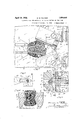
Figure 1 is a top plan view showing a pom pon and its support or handle in the relative positions which they initially occupy in nor- H mal operation;
Figure 2, a top plan view showing a pom pon, a support and an attaching member or device in operative position to receive a fastening member to be deformed into clamping engagement with said attaching member and said support;
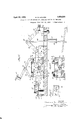
Figure 3, an enlarged fragmentary top plan view showing mechanism for guiding the attaching member and compressing the p p v Figure 4 3; fragmentary view partly in transverse section on the line .4l of Figure 3;
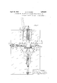
Figure 5, a view in transverse vertical section on the line 5-5 of Figure 1;
Figure 6, an enlarged fragmentary View partly in horizontal transverse-section illustrating in greater detail the relative positions of the pompon attaching member and the support just prior tothe operation of securing the attaching member to the support.
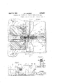
Figure 7 a view in perspective of one of a pair of cooperating jaws or stop members adapted to limit-movement of the pompon while permitting advance of free end portions of the attaching member into position to be engaged by the fastening means.
Figure 8, a fragmentary view partly in transverse vertical section showing the position of the parts just prior to the operation of theifastening member or clamp applying means and with a fastening member or clamp in normal operative position to be applied;
Figure 9,--a-transverse vertical section on the line 99 of Figure 6;
Figure 10, an enlarged fragmentary top plan view with portions broken away and with other portions shown in horizontal section illustrating the relative positions of the pompon, the attaching member, the support and the fastening or clamping member after the'clampin operation has been completed and before t e product'is released from engagement with the apparatus;
Figure 11, a transverse vertical section on the line 11'-11 of Figure 10;
Figure 12, a transverse vertical section on the'line 12-12 of Figure 1;
.Fi-gure .13, a view partly in vertical longitudinal section illustrating the relative positions ofthe operative-parts corresponding to'the positions thereof indicated in Figure 10;
Figure 14, a view partly in longitudinal section and with portions broken away to illustrate one form of product as it appears Whenremoved from the attaching apparatus.
Figure 15, a view with-portions broken away tozillustrate one form'of a complete grip strap or assist grip including a handle having a pompon attached in accordance with the present invention.
In practicing my improved method, I engage a group of strands forming a pompon or pompon blank transversely within the bight of-a U-shaped bail or attaching member 2 and efiiect compression of intermediate portions of said strands against the bail. While the blank is thus held firmly in position within the bight of said attaching-member, I
bring the free ends thereof into substantially parallel relation with the longitudinal axis of a support, as a handle or the like 3, said ends being adjacent to opposite sides of said handle. I then clamp said free ends securely into engagement with the handle, as by means of a fastening device, herein shown as-za staple, which, when deformed, takes the shape of aclamping ring encircling the free ends ofthe attaching member and a portion of'the handle. Where theblank is inthe form of a plurality of layers of strands, as more fullydiselosed in the .copending application of Herman H. Rubin, Serial No. 321,409, filed November'23, 1928, the stitches or other temporary strand retaining devices mayiconveniently. be removed after the pompon has been secured to its handle, and the .further steps for completing the shaping or sizing of the pompon may then be pursued as set forth in said pending application, or otherwise. However, so far as the present invention is concerned, my method is applicable to the attachment of a pompon whether in the blank form above mentioned or in any suitable intermediate or subsequent stage. After the described attachment has been effected, the free terminal portions of the U-shaped attaching device are preferably bent back towards the attached pompon, thus locking the pompon securely against endwise displacement. To form a complete commercially acceptable grip strap or assist grip,
it is customary to conceal the attaching and fastening devices hereinabove described by means of a ferrule 4, or by other suitable trimming or decorative expedients, as indicated in Figure 15.
A preferred form of apparatus for attaching a pompon or the like to a support or handle is shown in the drawings as including a base 5 upon which is mounted suitable means for retaining and guiding the attaching member or bail 2 with a pompon 1 or J the like assembled in operative relation thereto. Such means may conveniently include cooperating guide blocks 6 pivotally mounted at 7 and each provided with a longitudinally extending groove 8, Figure 4. WVhere the attaching member 2 takes the form of a wire bail or U-shaped piece of metal, the free ends thereof will slidably engage the groove 8 while the forward end of a presser member 9 mounted to slide toward and away from the pivoted blocks 6 engages the outer side of the bight.
The presser member 9 is illustrated as mounted on a carrier 10 arranged in sliding engagement between spaced guides 11 and the frame 5. The presser 9 together with its carrier 10 are moved forwardly and rearwardly by any suitable means, such as cooperating links 12 and 13, the latter being pivoted at 14 in the frame 5. These links As indicated more clearly in Figures 9 ill-1 and. 10, each block 6 is recessed to receive a slidable jaw or stop member 15 having an arm 16 extending through a slot 17. As indicated in Figure 5, each arm 16 carries a bracket 18. A spring 19 is interposed between and connects said brackets 18, thereby normally tending to pull the jaws 15 toward each other. A lever 20 is pivotally connected with one of the brackets 18 at 21 and another lever 22 is pivotally connected with the other bracket 18 at 23, the levers 20 and 22 being pivot-ally connected at 24.
By depressing the free end of lever 22, which i is preferably provided with a hand piece 25, the brackets 18 and consequently their respective corresponding aws or stop members 15 will be retracted from the forward normal position illustrated in Figure for a purpose hereinafter to be explained.
As will be more apparent from the disclosure of Figure 7, each of the jaws 15 is provided with an end recess 26 and a slot 27 extending through walls of said recess 26. As shown more clearly in Figures and 13, the jaws are mounted in the guide blocks 6 with their unrecessed sides exposed rearwardly or toward the advancing end of the presser member 9, while the recessed side is exposed in the opposite direction and positioned to conveniently receive and guide the forward end or butt of the support or handle 3, in proper relation to the free ends of the bail and to the fastener attaching mechanism hereinafter to be described. The slot 27 in each block 6 is aligned with the corresponding guiding groove 8 therein so that, as the bail 2 is advanced to the position indicated in Figure 6, the forward ends thereof will extend along said grooves 8 and thence through slots 27 and beyond the jaws 15 to a position substantially parallel with the longitudinal axis of handle 3 when the latter occupies the position indicated in Figure 6.
To conveniently and accurately position the butt or end of the handle 3 in operative relation to the bail ends, the handle is supported on a. carrier 28 having a handle receiving groove or channel 29. An extension of the carrier 28 is provided with a pair of spaced impaling members or pins 30 against the ends of which a forward portion of the handle may be pressed to retain the latter in suitable position for engagement with the devices hereinbefore described. In the illustrated form of my device, the impaling pins 30 are releasably held in operative position by means of athumb screw 31. r As indicated'n Figure 1, the carrier 28 forhandle 3 is slidably mounted on the base 5 between brackets 32. A link 33 is pivotally connected to carrier 28 and to an operating lever 34 which in turn is pivotally mounted on the base 5at 35. A stop or detent 36 limits the retractive movement of operating lever 34. A spring 37 is connected to lever 34 at 38 and to the base 5 at 39. In operation, when the .free end of lever 34 is deflected toward the base, the carrier 28 advances handle 3 and is normally retained in advanced operative position by spring 37 A stop 40 extends into the path of movement of lever 34, thus limiting the extent of forward movement of said lever and of carrier 28.
Referring now to Figure 2, each of the blocks 6 is provided with a lateral extension 41 adapted to engage a stop 42 mounted on base 5 and interposed in the path of said extension, said extensions 41 and stops 42 operating to limit the extent of movement of the rear ends of block 6 toward each other while the bail 2 is being moved into compressing engagement with the pompon or pompon blank and also while the bail is being retained in said pressing relation during operation of the fastener applying and deforming devices hereinafter to be described. The stops 42 also limit'the extent of movement of blocks 6 in the opposite or opening direction, as shown in Figure 1.
The mechanism hereinabove described may conveniently be operated to produce the intended result, somewhat as follows: The operator places a bail 2 in straddling engagement with a pompon blank or pompon, as the case may be, and arranges said bail and pompon in the initial position indicated in Figure 1. By deflecting the interconnected ends of links 12 and 13 downwardly, the presser member 9 advances the bail 2 between blocks 6 and into the position indicated in Figure 2. At this position, that portion of the pompon engaged by the bail 2 is compressed between the bight of said bail and the interposed faces of the sliding jaws 15 while the free ends of the bail project through slots 27. The handle 3 is then brought into operative position with relation to said bail and said pompon or pompon blank by deflecting the lever handle 34 as above described. The parts are now in such position that the free ends of the bail may conveniently be engaged and clamped into final assembled relation with the handle 3 by suitable fastener attaching or clamping means.v
A preferred embodiment of fastener attaching or clamping mechanism is adapted to present a staple-like fastening member in transverse straddling relation to end portions of the bail 2 and adjacent portions of the handle 3 and to deform or otherwise manipulate said staple in such a manner that it will be clamped around end portions of the bail and the handle 3.
As shown in Figure 5, a staple engaging moved to advanced position by means of an operating lever 46 pivoted to the base at 47 and provided at its inner end with a cam surface 48 positioned to effect sliding engagement with a roller 49 journaled on a shaft 50 which is mounted in a slot formed in carrier 51 to which the presser 43 is also connected. As shown in Figure 1, the operating lever 46 is in position to permit the presser 43 to occupy its retracted or inoperative position. A stop 52 limits the extent of movement of the operating lever 46 in this direction. As shown in Figure 2, the operating lever 46 is positioned to hold the presser 43 in advanced position and its movement toward said position is limited by means of a stop 53.
Opposite the presser 43, Figure 5, is a die or former 54 mounted on a suitable carrier 55 which in turn is slidably mounted on base 5. The die or former 54 is fashioned with a recess adapted to embrace a portion of a handle to which a pompon is intended to be attached and also to embrace a portion of a bail or the like by means of which the connection between the pompon and the handle is effected. The recessed portion of die 54 is also provided with a groove or channel 56 suitably shaped and proportioned to accommodate the free ends of a staple or staple-like fastening device and, when the presser 43 is brought into proper relation to the die 54, to deform said staple in such a way as to clamp the same securely around a handle and the ends of a bail when they are properly positioned across said groove 56. In Figure 6, the parts are shown in the relative positions which they occupy after an operator has placed a staple 5'7 with its bight in engagement with the presser 43 and with its free ends positioned to slide into engagement with the groove 56. Another view of this arrangement of the parts is shown in Figure 8.
Referring again to Figure 5, the carrier 55 is mounted to slide toward and away from the presser 43. For this purpose, I have provided a link 59 pivotally secured to the carrier 55 at 60 and a link 61 pivoted at 62 and pivotally connected with link 59 at 63. A rod 64 is pivotally connected to the links 59 and 61 at 63 and to a foot operated lever 65 at 66. A spring 67 has one end attached to av collar 68 and its other end attached to the base 5, said collar 68 being adjustably secured to the rod 64. The spring 67 tends normally to hold the carrier 55 in retracted position, as indicated in Figure 5. By pressing down the foot engaging portion of lever 65, the links 59 and 61 are deflected into extended relation, thus causing the carrier 55 to advance toward the presser 43. It will be noted that the pivotal connection between link 61 and base 5 is effected through an adjustable bracket 69, said bracket being retained in any desired position of adjustment by means of a nut 70 and a set screw 71 threaded in a fixed bracket 7 2. The mechanism just above described permits a fine adjustment and control of the movement of carrier 55 to accommodate the operation of the staple fastening means to different conditions encountered, such for example as variations in the length of staples to be used as fastening members.
In operation, the operator positions a staple as indicated in Figure 6 and, while holding the same in such position, depresses the free end of lever 65, Figure 5, until the groove 56 in die 54 encounters the end portions of said staple. He then retracts the presser 43 while advancing the die 54 and continues advancing die 54 until the parts reach the relative positions shown in Figure 11. During this operation, the free ends of staple 57 are gradually bent inwardly and in crossed relation to such extent that they completely encircle the handle 3 and the free ends of the bail 2. Upon releasing foot pres sure from the lever 65, carrier 55 is retracted and disengages the staple now in fixed position on the handle 3, leaving the pompon or pompon blank still held securely between the blocks 6 and jaws 15.
As hereinabove suggested, the links 12 and 13 are preferably actuated by another foot operated mechanism in all substantial respects similar to that which includes the lever 65. Accordingly, the operator normally holds the bail 2 and its engaged pompon in operative position by maintainin pressure on the other foot operated lever. As soon as the staple 57 has been attached, the operator releases said other foot operated lever controlling the position of links 12 and 13 to disengage the plunger 9 fromthe bail 2. The ends of the bail 2 are still engaged in the slots 27 of the sliding jaws 15. The operator now presses down on the free end of lever 22- to slide the jaws 15 laterally or outwardly and out of engagement with the ends of bail 2, thus freeing the bail and pompon so that they may be removed from the attaching apparatus together with the handle to which they are now secured.
It is contemplated that various mechanical equivalents may be substituted for the specific mechanisms referred to in the above description of a preferred form of my apparatus and that the sequence of steps defining my improved method may be varied with out material effect upon the intended results.
I claim as my invention:
1. Attaching apparatus comprising means for supporting ahandle or the like, means for supporting a Ushaped member in position with its free ends straddling an and portion of said handle, means for supporting a fastening member in transverse relation to said free ends of the U-shaped member, and means for deforming said fastening member into engagement with said free ends and said handle.
2. Attaching apparatus comprising means for supporting a handle or the like, means for supporting an attaching member with a longitudinally disposed portion in substantially parallel relation to the longitudinal axis of said handle, means for supporting a fastening member in transverse relation to said longitudinal portion, and means for deforming said fastening member into engagement with said longitudinal portion and said handle whereby said portion is securely clamped to said handle.
3. Apparatus for assembling a handle or the like and an object to be secured to an end thereof, comprising means for supporting said handle and an attaching member with said object-between them and with a longitudinally extending portion of the attaching member disposed in substantially parallel relation to the longitudinal axis of the handle, means for presenting a fastening member in transverse relation to said longi tudinal portion, means for holding a portion of said attaching member in compressing engagement with a portion of said object, and means for deforming the fastening member into engagement with said longitudinal portion of the attaching member to effectively clamp said member to said handle.
4. Apparatus for assembling a handle or the like and an object to be secured thereto, comprising means for supporting an object with an attaching member in compressing engagement with a portion thereof and with a disengaged portion extending beyond the compressed portion of said object, means for presenting a fastening member in transverse relation to said disengaged portion of the attaching member, and means for deforming said fastening member into clamping engagement with said disengaged portion of the attaching member.
5. Apparatus for assemling a handle or the like and an object to be secured to an end thereof by means of an attaching member, comprising supporting and guiding means for the attaching member, a stop for limiting the extent of movement of an object when positioned in operative relation to said attaching member, means for moving said attaching member toward said stop to compress a portion of said object between said attaching member and the stop while permitting a portion of said attaching member to move beyond said stop and into position for longitudinal engagement with a handle, means for attaching a clamping member in clamping engagement with said extending portion of the attaching member, and means for displacing the stop member from its effective osition to release the assembled product.
6. In attaching apparatus, the combination of opposed gui e members adapted to receive a substantially U-shaped bail or the like, means positioned to engage said bail to retain the same in operative position between said guides, and means for effecting relative movement between said bail engaging means and said bail guiding means to operatively position said bail.
7 In attaching apparatus, the combination of opposed guide members mounted for limited pivotal movement toward and away from each other and adapted to engage longitudinally disposed portions of a U-shaped bailor the like, means for engaging a transversely disposed portion of said bail, and means for effecting relative movement between said guide membersand said last men-' Eioned means to operatively position said ail.
8. In attaching apparatus, the combination of opposed guide blocks each having a longitudinally extending groove adapted to engage a longitudinal portion of a U-shaped bail, a jaw mounted to move transversely in relation to said groove and having a slot so positioned and arranged that when the jaws are in operative extended position their respective slots will be aligned with said longitudinal grooves, and means for moving said jaws to operative and inoperative positions respectively.
9. In attaching apparatus, the combination of a base, a pair of bail guiding members pivotally mounted in spaced relation on said base and having bail receiving grooves in their opposed faces, a aw slidably mounted at one end of each guiding member, said jaws being movable toward and away from each other, a bail presser, and means for effecting relative movement between said guiding member and said presser to present a bail engaging portion of said presser at will in oplgrative relation between said guiding memers.
10. In attaching apparatus, the combination of means for holding a U-shaped bail or the like with end port-ions straddling a handle or the like in a longitudinal direction, a former located at one side of the operative position of said handle and adapted to present guiding and deforming surfaces in the path of free end portions of a U-shaped fastener when the latter is in operative position to straddle said handle transversely, means at the other side of the operative position of said handle to engage another end portion of said fastener, and means for effecting relative movement between said former and said fastener engaging member whereby the fastener may be clamped around the handle.
11. Method of securing a pompon or the like to a handle or supporting member by means of a metallic attaching member including the steps of holding said pompon with an intermediate portion in compressed condition between a portion of said attaching member and an end of said handle, and applying a clamping member around said handle and another portion of said attaching member.
12. Method of securing a pompon or the like to a handle or supporting member by means of a metallic attaching member including the stepsofmoving said attaching member into position with a portion of said member in compressing engagement with an intermediate portion of said pompon, and clamping said attaching member to said handle While holding an end of said handle adj mom to the compressed portion of said pom- 011; p In testimony whereof I have signed my name to this specification this 12th day of November, 1929.
MAURICE M; BALSAM.
Priority Applications (1)
| Application Number | Priority Date | Filing Date | Title |
|---|---|---|---|
| US406793A US1854501A (en) | 1929-11-13 | 1929-11-13 | Apparatus for and method of attaching pompons or the like |
Applications Claiming Priority (1)
| Application Number | Priority Date | Filing Date | Title |
|---|---|---|---|
| US406793A US1854501A (en) | 1929-11-13 | 1929-11-13 | Apparatus for and method of attaching pompons or the like |
Publications (1)
| Publication Number | Publication Date |
|---|---|
| US1854501A true US1854501A (en) | 1932-04-19 |
Family
ID=23609475
Family Applications (1)
| Application Number | Title | Priority Date | Filing Date |
|---|---|---|---|
| US406793A Expired - Lifetime US1854501A (en) | 1929-11-13 | 1929-11-13 | Apparatus for and method of attaching pompons or the like |
Country Status (1)
| Country | Link |
|---|---|
| US (1) | US1854501A (en) |
-
1929
- 1929-11-13 US US406793A patent/US1854501A/en not_active Expired - Lifetime
Similar Documents
| Publication | Publication Date | Title |
|---|---|---|
| DE470138C (en) | Device for bundling rolling bars | |
| US3570554A (en) | Method of tieing a bundle of cables | |
| US1710261A (en) | Machine for forming interchangeable fashioned moldings | |
| US1854501A (en) | Apparatus for and method of attaching pompons or the like | |
| US3670782A (en) | Apparatus for tieing a bundle of cables | |
| US3587947A (en) | Apparatus for making a buckle and strap assembly | |
| US3252723A (en) | Cable lacing methods | |
| US1728048A (en) | Method of and apparatus for mounting filaments | |
| DE359195C (en) | Procedure for preparing upper leather and heel counter for pinching | |
| US2065754A (en) | Method of and means for stitching neckties | |
| DE69400045T2 (en) | Method and device for automatically stretching a knitted product drawn onto a form support | |
| US3102467A (en) | Automatic bundle tying machines | |
| US647037A (en) | Lasting-machine. | |
| DE969678C (en) | Device for overtaking and wrapping the upper leather in the manufacture of footwear | |
| DE404898C (en) | Method of applying the tread to the carcass | |
| US1400843A (en) | Stapling-machine for leather loops | |
| DE201501C (en) | ||
| US1831348A (en) | Machine for lacing shoe uppers | |
| US1687479A (en) | Buckle-strap severing and assembling machine | |
| DE1685430C3 (en) | Heel lasting machine | |
| AT107712B (en) | Method and machine for pinching footwear. | |
| DE664692C (en) | Machine for shaping and pinching the shoe upper over the last | |
| US1419201A (en) | Method of making shoes | |
| US1578536A (en) | Method of and means for producing reed fabric and the like | |
| DE445641C (en) | Method and device for connecting the ends of the straps of sleeve holders or of trouser straps with the buttonhole loop by means of a clad metal clip |