US1854495A - Lock housing assembly - Google Patents
Lock housing assembly Download PDFInfo
- Publication number
- US1854495A US1854495A US43959030A US1854495A US 1854495 A US1854495 A US 1854495A US 43959030 A US43959030 A US 43959030A US 1854495 A US1854495 A US 1854495A
- Authority
- US
- United States
- Prior art keywords
- lock
- housing
- lock cylinder
- plunger
- bolt
- Prior art date
- Legal status (The legal status is an assumption and is not a legal conclusion. Google has not performed a legal analysis and makes no representation as to the accuracy of the status listed.)
- Expired - Lifetime
Links
Images
Classifications
-
- E—FIXED CONSTRUCTIONS
- E05—LOCKS; KEYS; WINDOW OR DOOR FITTINGS; SAFES
- E05B—LOCKS; ACCESSORIES THEREFOR; HANDCUFFS
- E05B9/00—Lock casings or latch-mechanism casings ; Fastening locks or fasteners or parts thereof to the wing
- E05B9/04—Casings of cylinder locks
-
- Y—GENERAL TAGGING OF NEW TECHNOLOGICAL DEVELOPMENTS; GENERAL TAGGING OF CROSS-SECTIONAL TECHNOLOGIES SPANNING OVER SEVERAL SECTIONS OF THE IPC; TECHNICAL SUBJECTS COVERED BY FORMER USPC CROSS-REFERENCE ART COLLECTIONS [XRACs] AND DIGESTS
- Y10—TECHNICAL SUBJECTS COVERED BY FORMER USPC
- Y10T—TECHNICAL SUBJECTS COVERED BY FORMER US CLASSIFICATION
- Y10T70/00—Locks
- Y10T70/50—Special application
- Y10T70/5611—For control and machine elements
- Y10T70/5854—Bolt, nut, stud, stud-cap
- Y10T70/5858—Locked stationary
-
- Y—GENERAL TAGGING OF NEW TECHNOLOGICAL DEVELOPMENTS; GENERAL TAGGING OF CROSS-SECTIONAL TECHNOLOGIES SPANNING OVER SEVERAL SECTIONS OF THE IPC; TECHNICAL SUBJECTS COVERED BY FORMER USPC CROSS-REFERENCE ART COLLECTIONS [XRACs] AND DIGESTS
- Y10—TECHNICAL SUBJECTS COVERED BY FORMER USPC
- Y10T—TECHNICAL SUBJECTS COVERED BY FORMER US CLASSIFICATION
- Y10T70/00—Locks
- Y10T70/50—Special application
- Y10T70/5889—For automotive vehicles
- Y10T70/5982—Accessories
- Y10T70/5987—Spare or mounted wheel or tire
- Y10T70/5991—Tire or rim only
-
- Y—GENERAL TAGGING OF NEW TECHNOLOGICAL DEVELOPMENTS; GENERAL TAGGING OF CROSS-SECTIONAL TECHNOLOGIES SPANNING OVER SEVERAL SECTIONS OF THE IPC; TECHNICAL SUBJECTS COVERED BY FORMER USPC CROSS-REFERENCE ART COLLECTIONS [XRACs] AND DIGESTS
- Y10—TECHNICAL SUBJECTS COVERED BY FORMER USPC
- Y10T—TECHNICAL SUBJECTS COVERED BY FORMER US CLASSIFICATION
- Y10T70/00—Locks
- Y10T70/80—Parts, attachments, accessories and adjuncts
- Y10T70/8432—For key-operated mechanism
Definitions
- An object of this invention is to provide an assembly of a housing for a lock cylinder which is self-contained, and which is capable of endless modification in the various uses to which lock housings may be put, so that the housing may be mounted complete, as in 'any automobile or the like, so that the lockcylinders may be later supplied and inserted in the various assembled housings of the now practically completed automobile.
- Fig. 4 is a view similar to Fig. 3 after the retainer is assembled in the plunger;
- Fig-5 is a transverse section on the line 5 f of Fig. 4;
- Fig. 6 is an enlargedhorizontal section on the line 6 of Fig. 4;
- Fig. 7 is an enlarged perspective View of the retainer before being assembled in the plunger
- Fig.v 8 is ay greatly enlarged vperspective View of the plunger
- Fig. 9 is a view similar to Fig. 6 showing a modified form'of retainer in assembledV rwith only slight modification to all'the lock housings for use in the various parts of an automobile elsewhere.
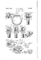
- the lock housing A is a lock screw having a cylindrical upper portion 10 passing through a shouldered opening in a locking arm B, while the screw threads engage a nut C whichis secured to to an automobile fender D, havingaJ fender well D in which is located a tire E on a rim E, the rim beingA retained therein by means of the locking arm B and the lock bolt A, as will hereinafter be more fully described.
- the lock bolt A is provided with a bore 11 in the upper portion which is adapted to receive a lock cylinder'F of any well known type, which isoperated by means lof a key F', and which carries at its lower endA an eccentric finger 12, which is adapted to retract a locking bolt or plunger 13 which is slidably fitted into a transverse opening 14 in the locking bolt A, and which is optionally urged outwardly bymeans of a compression spring 15.
- an object of this invention is to provide a means for assembling the lock bolt or plunger 13 in the lock cylinder housing A in such a way that this lock cylinder housing may be sent out as a unit, and as such may be assembled in the automobile or other similar mechanism, after which the lock cylinder F may be assembled.
- the plunger 13, together with its actuating spring 15, is placed in the lock cylinder housing after which a sleeve 16 is temporarily placed thereover so as to hold the plunger 13 in retracted position, as shown in Fig. 3.
- the plunger 13 is provided with a transverse slot 17 and a longitudinal hole v18, the slot 17 taking somewhat more than halfthe diameter of the plunger and providing Va flat seat 19, upon which theret-ainer 2O of Fig. 2 is adapted to lie.
- This retainer is made in angle'form, as shown in Fig. 7, in order to permit it to be assembled.
- the method of assembling is shown in Figs. 3 and 4.
- the retainer y2O is provided at each end .with tongues-.21 and 22 which are adapted to pass into the openings 185L and 18 respectively ofthe plunger13. .In-Fig 3 the tongue 21 1s shown in the opening 18a,-while the tongue 22 is vjust ready to enter the opening 18 at the opposite end.
- the Center portion of the retainer 20 is arched to permit the tongue 22 yto enter the opening 18, after which a bar 23 ,is inserted through the top of the housinglO,
- the main body of the retainer 2O is of the same width as the fiat-seat 19, ⁇ an'd has two outwardly extending ears 24 which, as shown in Fig. 6, engage-the cylindrical inner surface of the housing 10 and prevent theplunger 13 from moving outwardlyY beyond the-povsition shown.
- the plunger 13 is now a unitary-structure which is self-locking, softhat thecombination-'ofthe housing '10;and the plunger 13 is a unit and as-such separate manufacturer, if desired, and all brought in and assembled in a car by the automobile,manufacturer. lVith these all asse1nbled,.eXcept for-the loclrcylinder, the car manufacturer may now insert a set of lock cylinders in a single car, vall of which ications struction Yand arrangement may be made are substantial duplicates, and all of which may be operated by the same key.
- the lock housing A is provided with an annular lgroove 25 which servesto Vlock it permanently to thelocking arm B. This may be done either by means of arpin driven through. a corresponding hole in the locking Aarm B, or by means of an expanding snap ring which is adapted to snap outwardly into a corresponding annular groove 1n the arm B.
- the lock cylinder F is provided witha duplicate annular groove 26 into which Vfits a snap ring 27,-which is adapted. to snap outwardly into a corresponding annular .groove28 in the lock housing A.
- a ⁇ lock cylinder housing having a-bore adapted to receivea lock cylinder, a plunger movable transversely in said housing by said-lock cylinder, and means carried solely by said plungerfand insertable therein afterthe plunger is assembled insaid housingfor retaining the plunger assembled in saidhousing.
- a lock cylinder housing having a bore adapted to receive a lock cylinder, a plunger movable transversely in said housing by said lock cylinder, said plunger having a cut-away central portion terminating in an opening at each end thereof, and a retainer adapted to lie flat in said cutaway portion and having tongues adapted to engage said openings to retain the retainer in said plunger, said retainer having a laterally extending ear to retain the plunger in said housing.
- a lock cylinder housing having a bore adapted to receive a lock cylinder, a plunger movable transversely in said housing by said lock cylinder, and a retainer adapted to be permanently assembled in said plunger to retain said plunger assembled in said housing, said retainer hav ⁇ ing a lug for limiting the swing of the lock cylinder.
- a lock cylinder housing having a bore adapted to receive a lock cylinder, said housing having a side outlet, a locking bolt insertable through said outlet to extend transversely of said bore, a spring Within said bore tending to project lsaid bolt through said outlet, a stop attachment for said bolt applied thereto after insertion of said bolt through said outlet to thereafter limit the outward movement of said bolt, and a lock cylinder in said bore cooperable with said bolt to effect projection or retraction thereof relative to said outlet.
- a lock cylinder housing having a bore adapted to receive a lock cylinder, said housing having a side outlet, a locking bolt insertable through said outlet tov extend transversely of said bore, a spring Within said bore tending to project said bolt through said outlet, a stop attachment for said bolt applied thereto after insertion of said bolt through said outlet to thereafter limit the outward movement of said bolt, and a lock cylinder in said bore cooperable With said bolt to eii'ect projection or retraction thereof relative to said outlet, there being a projection on said attachment for limiting the movement of said lock cylinder.
- a lock mechanism a lock cylinder housing having a bore adapted to receive a lock cylinder, a lock bolt movable transversely in said housing and having a transverse notch, a cam operable by the lock cylinder to engage in said notch to control the shifting movement of said bolt into locking or unlocking position, and a retainer member seated in said notch and adapted to engage the housing Wall to limit the movement of said bolt.
- a lock cylinder housing having a bore adapted to receive a lock cylinder, a lock bolt movable transversely in said housing and having a transverse notch, a cam operable by the lock cylinder to engage in said notch to control the shift-
Landscapes
- Engineering & Computer Science (AREA)
- Mechanical Engineering (AREA)
- Lock And Its Accessories (AREA)
Description
Apri119,1932. EUAN slCKEL 1,854,495 LocK HOUSING ASSEMBLY Filed March 28, 1930 Patented Apr. 19, 1932 C UNiTED sra'i'Es EATENT oEFicE ERNEST J. VAN SICKEL, OF WAUKEGAN, ILLINOIS, ASSIGNOR TO OAKES PRODUCTS CORPORATION, OF NORTH CHICAGO, ILLINOISWA CORPORATION 0F MICHIGAN LOCK HOUSING ASSEMBLY Application iiiea March as, 1930. seriai No. 439,590.
It has been a common practice for automobile manufacturers in many instances to buy various key-controlled mechanisms, such as, ignition switch, door lock, spare wheel lock,
and the like, from various sources with the,
with others in the same set, thereby permitting a single key to be used for all locks which fare installed on a single car.
Various plans have been resorted to in the effort to utilizepin each car a number of lock cylinders7 all substantial duplicates of each other, made by the sanie manufacturer, and operable by a single key. rllhere have been certain practical difficulties in connection with this, however, owing to the fact that these parts could not be completely assembled until they reached the automobile manufacturer, and in the completed car to which they were to be assigned.
An object of this invention is to provide an assembly of a housing for a lock cylinder which is self-contained, and which is capable of endless modification in the various uses to which lock housings may be put, so that the housing may be mounted complete, as in 'any automobile or the like, so that the lockcylinders may be later supplied and inserted in the various assembled housings of the now practically completed automobile.
These and other objects, as will hereinafter appear, areI accomplished by this invention -Which is fully described in the following llock bolt for retaining the plunger while the retainer is being assembled;
Fig. 4 is a view similar to Fig. 3 after the retainer is assembled in the plunger;
Fig-5 is a transverse section on the line 5 f of Fig. 4;
Fig. 6 is an enlargedhorizontal section on the line 6 of Fig. 4; I
Fig. 7 is an enlarged perspective View of the retainer before being assembled in the plunger;
Fig.v 8 is ay greatly enlarged vperspective View of the plunger;
Fig. 9 is a view similar to Fig. 6 showing a modified form'of retainer in assembledV rwith only slight modification to all'the lock housings for use in the various parts of an automobile elsewhere. Y
Referring now to the drawings, the lock housing A is a lock screw having a cylindrical upper portion 10 passing through a shouldered opening in a locking arm B, while the screw threads engage a nut C whichis secured to to an automobile fender D, havingaJ fender well D in which is located a tire E on a rim E, the rim beingA retained therein by means of the locking arm B and the lock bolt A, as will hereinafter be more fully described.
The lock bolt A is provided with a bore 11 in the upper portion which is adapted to receive a lock cylinder'F of any well known type, which isoperated by means lof a key F', and which carries at its lower endA an eccentric finger 12, which is adapted to retract a locking bolt or plunger 13 which is slidably fitted into a transverse opening 14 in the locking bolt A, and which is optionally urged outwardly bymeans of a compression spring 15.
As earlier stated, an object of this invention is to provide a means for assembling the lock bolt or plunger 13 in the lock cylinder housing A in such a way that this lock cylinder housing may be sent out as a unit, and as such may be assembled in the automobile or other similar mechanism, after which the lock cylinder F may be assembled. To do this the plunger 13, together with its actuating spring 15, is placed in the lock cylinder housing after which a sleeve 16 is temporarily placed thereover so as to hold the plunger 13 in retracted position, as shown in Fig. 3.
Referring now to Fig. 8, the plunger 13 is provided with a transverse slot 17 and a longitudinal hole v18, the slot 17 taking somewhat more than halfthe diameter of the plunger and providing Va flat seat 19, upon which theret-ainer 2O of Fig. 2 is adapted to lie. This retainer is made in angle'form, as shown in Fig. 7, in order to permit it to be assembled. The method of assembling is shown in Figs. 3 and 4.
The retainer y2O is provided at each end .with tongues-.21 and 22 which are adapted to pass into the openings 185L and 18 respectively ofthe plunger13. .In-Fig 3 the tongue 21 1s shown in the opening 18a,-while the tongue 22 is vjust ready to enter the opening 18 at the opposite end. The Center portion of the retainer 20 is arched to permit the tongue 22 yto enter the opening 18, after which a bar 23 ,is inserted through the top of the housinglO,
as shown in dotted lines in Fig. 3. This is pressed down on the top of the-retainer 2O *and` struck a sharp blow with-a hammer not shown) so as to flatten out the retainer 20, as shown in Fig. 4, thereby forcing the tongue 22 into 4the opening 18, thereby vpermanently locking the retainer 2O to theplungerjl3.
The main body of the retainer 2O is of the same width as the fiat-seat 19,` an'd has two outwardly extending ears 24 which, as shown in Fig. 6, engage-the cylindrical inner surface of the housing 10 and prevent theplunger 13 from moving outwardlyY beyond the-povsition shown.
.Thus it will be seen that the plunger 13 :is now a unitary-structure which is self-locking, softhat thecombination-'ofthe housing '10;and the plunger 13 is a unit and as-such separate manufacturer, if desired, and all brought in and assembled in a car by the automobile,manufacturer. lVith these all asse1nbled,.eXcept for-the loclrcylinder, the car manufacturer may now insert a set of lock cylinders in a single car, vall of which ications struction Yand arrangement may be made are substantial duplicates, and all of which may be operated by the same key.
It will be apparent that a great deal of lost motion is thus avoided, such as would be occasioned where the car manufacturer were to send out a series of say, four lock assemblies to four separateparts manufacturers. When these parts came back with the locks assembled therein it would then be necessary to pick out these parts having duplicate locks out of the parts thus received in order to assemble in a single car locks which are duplicates. All this is avoided by the present. invention.
The lock housing A is provided with an annular lgroove 25 which servesto Vlock it permanently to thelocking arm B. This may be done either by means of arpin driven through. a corresponding hole in the locking Aarm B, or by means of an expanding snap ring which is adapted to snap outwardly into a corresponding annular groove 1n the arm B. VLikewise the lock cylinder F is provided witha duplicate annular groove 26 into which Vfits a snap ring 27,-which is adapted. to snap outwardly into a corresponding annular .groove28 in the lock housing A. `Tl-rusto complete'the installation, the carmanufacturerforces thelockpcylinder F down until the snap ring 27 snaps outwardly intothe groove 28,y thereby:` locking theV twoy together after which they ycannot be disassembled without considerable'injury to the parts.
The rotationv of thelock Acylinder vF in the housing A is limited by means of 4a pin 29 operating ina slot 43() in the end of the lock cylinder. T hisvlimitation ofthe rotation of the lock cylinder is otherwiseprovided for in Figs..9 and 10, in which the retainer 2On has in addition to thefeatures of the retainer 20 a pressed up lug31 which serves as a limiting -stop .for the eccentric finger 12, which is shown in dotted line position in Fig. 9. In orderfthat itmay act falso asa stop :at theinner vswing of'theplunger 13,
therears 24a are made somewhat wider Iand Vslightly overhang the sides of the plunger 13 as' there shown.
lVhile I have shownand described but a few embodiments of my invention, it is to be understood that it isl capable of many modi- Changes, therefore, in the conwhich do not departfrom the-spirit'and scope of the invention as coveredby the appended claims.
I claim:
1. In a lock mechanism,.a `lock cylinder housing having a-bore adapted to receivea lock cylinder, a plunger movable transversely in said housing by said-lock cylinder, and means carried solely by said plungerfand insertable therein afterthe plunger is assembled insaid housingfor retaining the plunger assembled in saidhousing.
2. In a lock mechanism, a lock cylinder housing having a bore adapted to receive a lock cylinder, a plunger movable transversely in said housing by said lock cylinder, said plunger having a cut-away central portion terminating in an opening at each end thereof, and a retainer adapted to lie flat in said cutaway portion and having tongues adapted to engage said openings to retain the retainer in said plunger, said retainer having a laterally extending ear to retain the plunger in said housing.
3. In a lock mechanism, a lock cylinder housing having a bore adapted to receive a lock cylinder, a plunger movable transversely in said housing by said lock cylinder, and a retainer adapted to be permanently assembled in said plunger to retain said plunger assembled in said housing, said retainer hav` ing a lug for limiting the swing of the lock cylinder.
4. In a lock mechanism, a lock cylinder housing having a bore adapted to receive a lock cylinder, said housing having a side outlet, a locking bolt insertable through said outlet to extend transversely of said bore, a spring Within said bore tending to project lsaid bolt through said outlet, a stop attachment for said bolt applied thereto after insertion of said bolt through said outlet to thereafter limit the outward movement of said bolt, and a lock cylinder in said bore cooperable with said bolt to effect projection or retraction thereof relative to said outlet.
5. In a lock mechanism, a lock cylinder housing having a bore adapted to receive a lock cylinder, said housing having a side outlet, a locking bolt insertable through said outlet tov extend transversely of said bore, a spring Within said bore tending to project said bolt through said outlet, a stop attachment for said bolt applied thereto after insertion of said bolt through said outlet to thereafter limit the outward movement of said bolt, and a lock cylinder in said bore cooperable With said bolt to eii'ect projection or retraction thereof relative to said outlet, there being a projection on said attachment for limiting the movement of said lock cylinder.
6. In a lock mechanism, a lock cylinder housing having a bore adapted to receive a lock cylinder, a lock bolt movable transversely in said housing and having a transverse notch, a cam operable by the lock cylinder to engage in said notch to control the shifting movement of said bolt into locking or unlocking position, and a retainer member seated in said notch and adapted to engage the housing Wall to limit the movement of said bolt.
7 In a lock mechanism, a lock cylinder housing having a bore adapted to receive a lock cylinder, a lock bolt movable transversely in said housing and having a transverse notch, a cam operable by the lock cylinder to engage in said notch to control the shift-
Priority Applications (1)
| Application Number | Priority Date | Filing Date | Title |
|---|---|---|---|
| US43959030 US1854495A (en) | 1930-03-28 | 1930-03-28 | Lock housing assembly |
Applications Claiming Priority (1)
| Application Number | Priority Date | Filing Date | Title |
|---|---|---|---|
| US43959030 US1854495A (en) | 1930-03-28 | 1930-03-28 | Lock housing assembly |
Publications (1)
| Publication Number | Publication Date |
|---|---|
| US1854495A true US1854495A (en) | 1932-04-19 |
Family
ID=23745324
Family Applications (1)
| Application Number | Title | Priority Date | Filing Date |
|---|---|---|---|
| US43959030 Expired - Lifetime US1854495A (en) | 1930-03-28 | 1930-03-28 | Lock housing assembly |
Country Status (1)
| Country | Link |
|---|---|
| US (1) | US1854495A (en) |
Cited By (1)
| Publication number | Priority date | Publication date | Assignee | Title |
|---|---|---|---|---|
| US4466261A (en) * | 1980-10-20 | 1984-08-21 | Zimmer John C | Security apparatus |
-
1930
- 1930-03-28 US US43959030 patent/US1854495A/en not_active Expired - Lifetime
Cited By (1)
| Publication number | Priority date | Publication date | Assignee | Title |
|---|---|---|---|---|
| US4466261A (en) * | 1980-10-20 | 1984-08-21 | Zimmer John C | Security apparatus |
Similar Documents
| Publication | Publication Date | Title |
|---|---|---|
| US1736900A (en) | Steering-wheel lock for automobiles | |
| US6298938B1 (en) | Locking device for the steering system of motor vehicles | |
| US2691288A (en) | Padlock | |
| GB1383137A (en) | Steering column lock for an automobile | |
| GB1355188A (en) | Keys for cylinder type locks and to locks operated thereby | |
| US1891214A (en) | Lock | |
| US1681409A (en) | Spare-tire lock | |
| GB1297747A (en) | ||
| US1854495A (en) | Lock housing assembly | |
| US2039244A (en) | Lock | |
| US2221082A (en) | Coincidental lock | |
| US2709356A (en) | Portable antitheft device | |
| US2329309A (en) | Coincidental locking system for automobiles | |
| US1542442A (en) | Padlock | |
| US1516418A (en) | Wheel lock | |
| US2217234A (en) | Trailer hitch | |
| US1875734A (en) | Spare tire and rim lock | |
| US1436585A (en) | Automobile lock | |
| US3289782A (en) | Safety automobile door locking device | |
| US1720804A (en) | Latch spindle and lock assembly | |
| US1629015A (en) | Spare-tire lock | |
| US1744340A (en) | Lock | |
| US1795547A (en) | Adjustable steering-post lock | |
| US1366066A (en) | Steering-wheel lock | |
| US1408237A (en) | Automobile lock |