US1854486A - Process and apparatus for producing abrasive articles - Google Patents
Process and apparatus for producing abrasive articles Download PDFInfo
- Publication number
- US1854486A US1854486A US121259A US12125926A US1854486A US 1854486 A US1854486 A US 1854486A US 121259 A US121259 A US 121259A US 12125926 A US12125926 A US 12125926A US 1854486 A US1854486 A US 1854486A
- Authority
- US
- United States
- Prior art keywords
- wool
- same
- rolls
- steel wool
- abrasive articles
- Prior art date
- Legal status (The legal status is an assumption and is not a legal conclusion. Google has not performed a legal analysis and makes no representation as to the accuracy of the status listed.)
- Expired - Lifetime
Links
- 238000000034 method Methods 0.000 title description 10
- 210000002268 wool Anatomy 0.000 description 50
- 229910000831 Steel Inorganic materials 0.000 description 28
- 239000010959 steel Substances 0.000 description 28
- 238000009958 sewing Methods 0.000 description 9
- 239000000463 material Substances 0.000 description 8
- 238000003825 pressing Methods 0.000 description 6
- 238000004519 manufacturing process Methods 0.000 description 4
- 238000010276 construction Methods 0.000 description 3
- 230000004048 modification Effects 0.000 description 2
- 238000012986 modification Methods 0.000 description 2
- 238000009991 scouring Methods 0.000 description 2
- 239000011121 hardwood Substances 0.000 description 1
- 239000004922 lacquer Substances 0.000 description 1
- 238000005498 polishing Methods 0.000 description 1
- 239000002966 varnish Substances 0.000 description 1
Images
Classifications
-
- D—TEXTILES; PAPER
- D05—SEWING; EMBROIDERING; TUFTING
- D05B—SEWING
- D05B23/00—Sewing apparatus or machines not otherwise provided for
-
- D—TEXTILES; PAPER
- D05—SEWING; EMBROIDERING; TUFTING
- D05D—INDEXING SCHEME ASSOCIATED WITH SUBCLASSES D05B AND D05C, RELATING TO SEWING, EMBROIDERING AND TUFTING
- D05D2303/00—Applied objects or articles
- D05D2303/30—Fibre mats
-
- D—TEXTILES; PAPER
- D05—SEWING; EMBROIDERING; TUFTING
- D05D—INDEXING SCHEME ASSOCIATED WITH SUBCLASSES D05B AND D05C, RELATING TO SEWING, EMBROIDERING AND TUFTING
- D05D2305/00—Operations on the work before or after sewing
- D05D2305/02—Folding
- D05D2305/06—Folding transversally
Definitions
- PROCESS AND APPARATUS FOR PRODUCING ABRASIVE ARTICLES Filed ly 1926 3 Sheets-Sheet 2 IIIIIIZ l-llllll llllllW/Ail 1 II Silllllx Illl @IIIIIIIW/A 129M. wa. M MM @5.
- marcelled steel wool by securing marcelled steel wool to a fiexible base or backing member.
- My invention consists, generally stated, in the novel process and apparatus having the novel arrangement, construction and combl- 3 nation of parts as hereinafter more specifically set forth and described and particularly pointed out in the claims.
- the object of my invention is to provlde abrasive articles by sewing steel wool onto a if flexible base or backing member in a continuous operation and to so form the wool that the stitches caused by the sewing will embed themselves into parts thereof where they will be unaffected by the use of the article for
- a flexible backing member such as heavy ducking or webbing
- I may provide continuous curvilinear depressions uniformly spaced with 2. Marcel wave between each depression,
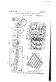
- Figure 1 1s a diagrammatic side elevation showing the arrangement of the parts used in my apparatus for manufacturing abrasive articles
- r Fig. 2 is a top plan view of the marcelling roll and adjacent parts
- Fig. 3 is a perspective view of a portion of the article manufactured in the device shown in Fig. 1;
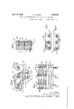
- Fig. 4 is an enlarged sectional view of the crisscrossing members and showing the eccentric feed bars in connection therewith;
- Fig. 5 is a top plan view of the feed bars showing a part thereof in section taken on the line 5-5 of Fig. 4;
- Fig. 6 is a' bottom plan vie-w of the crisscrossing members showing part of the same in section;
- V Fig. 7 is avertical sectional view taken on the line 77 of Fig. 6
- Fig. 8 is a like view taken on of Fig. 6;
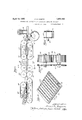
- Fig. 9 is a diagrammatic side elevation showing the arrangement of parts in the apparatus used for manufacturing the abrasive articles, with transverse marcels therein;
- Fig. 10 is an end view of the marcelling rolls showing the manner in which the same are geared together;
- Fig. 11 is a like view of the marginal flattoning rollers taken on the line 1111 of Fig. 9;and-
- Fig. 12 is a perspective view of a section of the article having the Marcel waves therein formed transverse to the direction of travel of the same through the apparatus shown in Fig. 9.
- my improved apparatus for manufacturing abrasive articles comprises a pair of rolls 16 and 17 carrying a belt 18, and said rolls are rotated in the direction shown by the arrows, while the belt 18 in its travel between the upper faces of the said rolls engages with a series of idle rollers 19 which are suitably mounted in a table 21.
- a belt 23 passes over the same and around a larger roll 24, whose periphery is slightly above the to p of the table 21, so that when the belt 23 is mounted on said rolls the same converges inwardly on its lower end so that steel wool 26 fed onto the belt 18 will be carried into the converging opening and pressed to form a flat mass at the point 27 between the roll 24: and the end of the table 21.
- the belts l8 and 23 are provided with metallic fingers 28 which on the opposing belts lie between each other so as to stagger the same at the point 27, and these fingers are adapted to place crimps in the steel wool as it passes through said point so that the wool may be readily engaged by the serrated or toothed lower face 29 of the eccentric feed bar 30.
- This feed bar is provided with an eccentric shaft 32 and has circular openings 33 at each end of the same into which are placed idle rolls 3 1 which are mounted on stationary pins 36 so that when the shaft 32 is rotated the said bar will. be given an eccentric movement so as to intermittently cause the serrated lower face 29 thereof to engage with the steel wool from the belts 18 and 23.
- the members 37 have their common eccentric shaft 41 at the right-hand side of the same and the two idle rollers 42 in the other openings shown therein; otherwise they are exactly the same as the feed bar 30 above described.
- the member 37?) has its eccentric shaft 43 in the left-hand end of the same and its two idle rollers 14 in the center and at the other end thereof, and it is in like manner precisely the same as the feed bar 30 above shown except for the position of its eccentric shaft.
- the three members 30, 37a. and 37?) are designed and geared to operate 120 apart; that is to say, the serrated face 29 of the feed bar 30 will engage with and advance the steel wool 26 therein less than one-third of a complete cycle of360, whereupon the crisscrossing members 370; will engage with and carry the strands of the steel wool out of line with the direction of their length for something less than the next 120 of the cycle, and as the cam shaft 41 therein is disengaging the serrated faces 38 of said members from the strands which they have pulled out of parallel relation with the remaining strands, the serrated faces 39 of the members 376 will engage the strands of the steel wool and pull some of them in the other direction and out of line with the length of the same, so that the strands of steel wool will be crisscrossed.
- These latter members 37?) will perform their function during the final 120 of the complete cycle, so that when they are withdrawn from their engagement with the wool by the cam shaft 43, a new cycle is about to commence and the
- the wool is carried on a table 16, and above the same are corresponding plates &7 for keeping the same flattened until it enters the rolls 18 and 49, which are adjustably mounted and adapted to further press and flatten the wool before it is engaged by the ma-rcelling rolls 51 and 52.
- These rolls are provided with circumferential teeth '53, and as the wool passes therebetween, it is marcelled and provided with the waves 54 having the depressions 56 between the same.
- a bed-plate 57 which has flutes 58 extending longitudinally therein, and a pair of shafts 59 and 61 above the same carry staggered rolls 62 and 63, whose pointed peripheries 64 engage with the depressions 56 in the said wool and hold the waves in shape.
- a converging webbing feeder 66 which consists of the feed rollers 67 and 68 and the idle roller 69, and the webbing 71 carried on the roll 72 is fed under the marcelled steel wool and a stitching machine 73 of any desired construction sews the steel wool to the webbing through each of the depressions 56 simultaneously.
- the rolls 16, 17, and 24 carryin the belts 18 and 23 are precisely the same as shown in Fig. i, and the squeezing and pressing rollers #18 and 4:9 correspond with those shown in Fig. 1 and are employed for the purpose of flattening the material as it passes therebetween, while beyond these rolls is a bridge member 76 for taking care of any slack in the material as it is drawn into the marcelling rolls 77 and 78.
- These rolls are provided with intermeshing gears '7 9 and 81 and have their teeth 82 out transverse of the circumference of said rolls so that the marcels formed in the material passing therethrough is transverse to the direction of the length of the strands thereof, and as it emerges from said rolls it is engaged by the edge flattening rolls 83 mounted ona shaft 84 for squeezing the said edges down preparatory to overstitching the same in a later operation.
- the material After passing through the rollers 83 the material is engaged by the belts 86 and 87 carried on the rolls 88 and 89, and 91 and 92, respectively, and the space between the said pairs of rolls is provided with a lower table 93 and an upper table 94 for backing up the belts as they pass together between the same, and these belts are provided with metallic toothed members 96 and 97, respectively, which correspond in size and shape to the teeth 82 on the marcelling rollers 77 and 7 8, and retain the mar cels in pro-per shape until the wool is engaged by the webbing 71 from the roll 72 fed underneath the same by the rolls 67 and 68, which operates in precisely the same manner as the description thereof given in connection with the operation of the apparatus shown in Fig. 1.
- This device is also provided with a stitching machine 98, but in this instance the machine is what is commonly known as an overcaster and stitches the flattened outer edges 99 to the webbing as the same passes therethrough.
- the steel wool may be stitched in the depressions 100 between the waves 101 after the material has passed the stitching machine 98, or a transverse stitching machine may be employed for providing siX or more transverse stitches simultaneously in the depressions 100 after the same has passed the stitching member 98.
- the articles manufactured by my improved process and in the apparatus shown and described herein may be used for various purposes, such, for instance, as for belts, where a definite frictional contact with the rolls is desired, and the same may be cut into small pads for polishing varnishes, lacquers, and the like, or may be used for domestic pur poses in the scouring of articles desired to be cleaned and polished.
- the pads will also be found very effective in finishing hardwood surfaces and any other places where a smooth, glossy finish is desired.
- An apparatus for producing abrasive articles comprising means for feeding steel wool, means for crisscrossing the strands thereof, means for marcelling the same, and means for sewing said wool to a flexible backing member.
- An apparatus for producing abrasive articles comprising converging belts for receiving and pressing steel wool to a substantially flat mass, means for crisscrossing the strands thereof, means for marcelling the same, and means for sewing said wool to a flexible backing member.
- An appartus for producing abrasive articles comprising converging belts for receiving and pressing steel wool to a substantially flat mass, eccentric members for crisscrossing the strands thereof, mean for marcelling the same, and means for sewing said wool to a flexible backing member.
- An appartus for producingv abrasive articles comprising converging belts for receiving and pressing steel wool to a substantially flat mass, means for crisscrossing the strands thereof, interlocking toothed member for marcelling the same, and means for sewing said wool to a flexible backing member.
- An apparatus for producing abrasive articles comprising converging belts for receiving and pressing steel wool to a substantially flat mass, eccentric members for crisscrossing the strands thereof, interlocln'ng toothed members for marcelling the same, and means for sewing the said wool to a flexible backing member.
- An apparatus for producing abrasive articles comprising converging belts for receiving and pressing metallic wool to a substantially flat mass, means for crisscrossing the strands thereof, means for marcelling the same, means for feeding a flexible member adjacent to said flat mass of wool and means for sewing said wool to said member.
- the method of producing an abrasive article which comprises causing :a strip of steel wool whose filaments are in a substantially parallel position to travel longitudinail ly, ncrissorossing said filaments to compact the same; forming Marcel Waves in said compacted steel Wool and sewing said steel WOOl to a flexible backing member.
Landscapes
- Engineering & Computer Science (AREA)
- Textile Engineering (AREA)
- Treatment Of Fiber Materials (AREA)
Description
April 19, 1932.
J. B. ROGERS 1,354,486 ATUS FOR ASI April 19, J 5 G R 1,854,486
PROCESS AND APPARATUS FOR PRODUCING ABRASIVE ARTICLES Filed ly 1926 3 Sheets-Sheet 2 IIIIIIZ l-llllll llllllW/Ail 1 II Silllllx Illl @IIIIIIIW/A 129M. wa. M MM @5.
'Apiil 19', 1932. 'J. B. ROGERS PROCESS AND APPARATUS FOR PRODUCING ABRASIVE ARTICLES Filed July 8, 1926 3 Sheets-Sheet Iii mm JZLHLQSAB. Jew @719 frictional or scouring purposes.
waves of the marcelling.
Patented Apr. 19, 1932 JAMES B. ROGER-S, OF CHICAGO, ILLINOIS, ASSIGNOR, BY DIRECT AND MESNE ASSIGN- MENTS, 'IO STEEL WOOL PAD CORPORATION, OF CHICAGO, ILLINOIS, A CORPORA- IION OF DELAWARE PROCESS AND APPARATUS FOR PRODUCING ABRASIVE ARTICLES Application, filed July 8, 1926. Serial No. 121,259.
by securing marcelled steel wool to a fiexible base or backing member.
My invention consists, generally stated, in the novel process and apparatus having the novel arrangement, construction and combl- 3 nation of parts as hereinafter more specifically set forth and described and particularly pointed out in the claims.
The object of my invention is to provlde abrasive articles by sewing steel wool onto a if flexible base or backing member in a continuous operation and to so form the wool that the stitches caused by the sewing will embed themselves into parts thereof where they will be unaffected by the use of the article for In order to effectually accomplish this result, I compress the steel wool into a flat mass of the required width and then pass same through members having intermeshing teeth which produce Marcel waves either longitudinally or transversely and then this marcelled wool is brought into proper relation with a flexible backing member, such as heavy ducking or webbing, and is stitched thereto between the When the article is used, the Marcel waves are flattened down and the stitches are embedded thereunder so that they will not come in contact with the surface against which the wool is pressed and thus all danger of their being cut'or otherwise injured is eliminated.
In the manufacture of my improved abrasive articles, I prefer to employ steel wool whose strands are substantially parallel, as
such material has been found by experiment to produce the best results, and when the marcel wave is produced substantially parallel with the length of the strands, I may employ members for crisscrossing the strands so that the longitudinal stitching will catch all strands and hold them securely to the flexible backing member.
In some cases I may provide continuous curvilinear depressions uniformly spaced with 2. Marcel wave between each depression,
and when the stitching is performed unifcrmly along the said curvilinear depressions, all the strands of the wool will be secured to the flexible backing member without the necessity of employing the crisscrossing members.
Further objects and advantages of my invention will be manifest to those skilled in the art as the same becomes better understood by reference to the following description when considered in connection with the accompanying drawings, in which Figure 1 1s a diagrammatic side elevation showing the arrangement of the parts used in my apparatus for manufacturing abrasive articles;
r Fig. 2 is a top plan view of the marcelling roll and adjacent parts;
Fig. 3 is a perspective view of a portion of the article manufactured in the device shown in Fig. 1;
Fig. 4; is an enlarged sectional view of the crisscrossing members and showing the eccentric feed bars in connection therewith;
Fig. 5 is a top plan view of the feed bars showing a part thereof in section taken on the line 5-5 of Fig. 4;
Fig. 6 is a' bottom plan vie-w of the crisscrossing members showing part of the same in section;
V Fig. 7 is avertical sectional view taken on the line 77 of Fig. 6
Fig. 8 is a like view taken on of Fig. 6;
Fig. 9 is a diagrammatic side elevation showing the arrangement of parts in the apparatus used for manufacturing the abrasive articles, with transverse marcels therein;
Fig. 10 is an end view of the marcelling rolls showing the manner in which the same are geared together;
Fig. 11 is a like view of the marginal flattoning rollers taken on the line 1111 of Fig. 9;and-
Fig. 12 is a perspective view of a section of the article having the Marcel waves therein formed transverse to the direction of travel of the same through the apparatus shown in Fig. 9.
In the several drawings, like reference characters indicate like parts.
the line8 8 As illustrated in Figure 1, my improved apparatus for manufacturing abrasive articles comprises a pair of rolls 16 and 17 carrying a belt 18, and said rolls are rotated in the direction shown by the arrows, while the belt 18 in its travel between the upper faces of the said rolls engages with a series of idle rollers 19 which are suitably mounted in a table 21. At a suitable distance above the table 21 there is a small roll 22, and a belt 23 passes over the same and around a larger roll 24, whose periphery is slightly above the to p of the table 21, so that when the belt 23 is mounted on said rolls the same converges inwardly on its lower end so that steel wool 26 fed onto the belt 18 will be carried into the converging opening and pressed to form a flat mass at the point 27 between the roll 24: and the end of the table 21. The belts l8 and 23 are provided with metallic fingers 28 which on the opposing belts lie between each other so as to stagger the same at the point 27, and these fingers are adapted to place crimps in the steel wool as it passes through said point so that the wool may be readily engaged by the serrated or toothed lower face 29 of the eccentric feed bar 30. This feed bar is provided with an eccentric shaft 32 and has circular openings 33 at each end of the same into which are placed idle rolls 3 1 which are mounted on stationary pins 36 so that when the shaft 32 is rotated the said bar will. be given an eccentric movement so as to intermittently cause the serrated lower face 29 thereof to engage with the steel wool from the belts 18 and 23.
Below the eccentric feed bar 30 are the crisscrossing members 37. These members are staggered, as shown in the drawings, and every other one of the same has its serrated or toothed face 38 extending in the direction shown in Fig. 7, while the other members have their serrated or toothed faces 39 eX- tending in the direction shown in Fig. 8. The members 37a have their common eccentric shaft 41 at the right-hand side of the same and the two idle rollers 42 in the other openings shown therein; otherwise they are exactly the same as the feed bar 30 above described. The member 37?) has its eccentric shaft 43 in the left-hand end of the same and its two idle rollers 14 in the center and at the other end thereof, and it is in like manner precisely the same as the feed bar 30 above shown except for the position of its eccentric shaft.
The three members 30, 37a. and 37?) are designed and geared to operate 120 apart; that is to say, the serrated face 29 of the feed bar 30 will engage with and advance the steel wool 26 therein less than one-third of a complete cycle of360, whereupon the crisscrossing members 370; will engage with and carry the strands of the steel wool out of line with the direction of their length for something less than the next 120 of the cycle, and as the cam shaft 41 therein is disengaging the serrated faces 38 of said members from the strands which they have pulled out of parallel relation with the remaining strands, the serrated faces 39 of the members 376 will engage the strands of the steel wool and pull some of them in the other direction and out of line with the length of the same, so that the strands of steel wool will be crisscrossed. These latter members 37?) will perform their function during the final 120 of the complete cycle, so that when they are withdrawn from their engagement with the wool by the cam shaft 43, a new cycle is about to commence and the feed bar 30 is ready to advance the material by its serrated face 29.
The wool is carried on a table 16, and above the same are corresponding plates &7 for keeping the same flattened until it enters the rolls 18 and 49, which are adjustably mounted and adapted to further press and flatten the wool before it is engaged by the ma-rcelling rolls 51 and 52. These rolls are provided with circumferential teeth '53, and as the wool passes therebetween, it is marcelled and provided with the waves 54 having the depressions 56 between the same. Immediately beyond the marcelling rolls 51 and 52 is a bed-plate 57 which has flutes 58 extending longitudinally therein, and a pair of shafts 59 and 61 above the same carry staggered rolls 62 and 63, whose pointed peripheries 64 engage with the depressions 56 in the said wool and hold the waves in shape.
At the rear of the fluted bed-plate 57 is a converging webbing feeder 66, which consists of the feed rollers 67 and 68 and the idle roller 69, and the webbing 71 carried on the roll 72 is fed under the marcelled steel wool and a stitching machine 73 of any desired construction sews the steel wool to the webbing through each of the depressions 56 simultaneously.
It will be necessary to synchronize the rollers 16, 17, 22 and 2 1, the rolls 48 and 19, the marcel rolls 51 52, and the webbing feeder rolls 67 and 68 in order that the steel wool will have a uniform linear advancement throughout the apparatus, but this is all accomplished by means of gearing the several rollers in their proper relations, all of which is a matter of mechanical detail and has been thought to be unnecessary to show and describe herein.
In the device shown in Fig. 9, the rolls 16, 17, and 24 carryin the belts 18 and 23 are precisely the same as shown in Fig. i, and the squeezing and pressing rollers # 18 and 4:9 correspond with those shown in Fig. 1 and are employed for the purpose of flattening the material as it passes therebetween, while beyond these rolls is a bridge member 76 for taking care of any slack in the material as it is drawn into the marcelling rolls 77 and 78. These rolls are provided with intermeshing gears '7 9 and 81 and have their teeth 82 out transverse of the circumference of said rolls so that the marcels formed in the material passing therethrough is transverse to the direction of the length of the strands thereof, and as it emerges from said rolls it is engaged by the edge flattening rolls 83 mounted ona shaft 84 for squeezing the said edges down preparatory to overstitching the same in a later operation. After passing through the rollers 83 the material is engaged by the belts 86 and 87 carried on the rolls 88 and 89, and 91 and 92, respectively, and the space between the said pairs of rolls is provided with a lower table 93 and an upper table 94 for backing up the belts as they pass together between the same, and these belts are provided with metallic toothed members 96 and 97, respectively, which correspond in size and shape to the teeth 82 on the marcelling rollers 77 and 7 8, and retain the mar cels in pro-per shape until the wool is engaged by the webbing 71 from the roll 72 fed underneath the same by the rolls 67 and 68, which operates in precisely the same manner as the description thereof given in connection with the operation of the apparatus shown in Fig. 1. This device is also provided with a stitching machine 98, but in this instance the machine is what is commonly known as an overcaster and stitches the flattened outer edges 99 to the webbing as the same passes therethrough. The steel wool may be stitched in the depressions 100 between the waves 101 after the material has passed the stitching machine 98, or a transverse stitching machine may be employed for providing siX or more transverse stitches simultaneously in the depressions 100 after the same has passed the stitching member 98.
The articles manufactured by my improved process and in the apparatus shown and described herein may be used for various purposes, such, for instance, as for belts, where a definite frictional contact with the rolls is desired, and the same may be cut into small pads for polishing varnishes, lacquers, and the like, or may be used for domestic pur poses in the scouring of articles desired to be cleaned and polished. The pads will also be found very effective in finishing hardwood surfaces and any other places where a smooth, glossy finish is desired.
To carry out my improved process I have shown and described an apparatus which automatically advances the wool through the several required steps and brings the flexible webbing into proper relation with the wool for being sewn thereto. These steps are all accomplished mechanically, and no manual labor is required except to start the wool and webbing in its proper course.
While I have shown and described a pre ferred embodiment of my invention and disclosed uses for the completed article, it should be understood that the details of construction are capableof wide modification and variation without departing from the spirit of the invention or sacrificing any of its advantages. 1 therefore reserve all such variations, modifications, and mechanical equivalents as fall within the spirit and scope of the appended claims.
I claim:
1. An apparatus for producing abrasive articles, comprising means for feeding steel wool, means for crisscrossing the strands thereof, means for marcelling the same, and means for sewing said wool to a flexible backing member.
2. An apparatus for producing abrasive articles, comprising converging belts for receiving and pressing steel wool to a substantially flat mass, means for crisscrossing the strands thereof, means for marcelling the same, and means for sewing said wool to a flexible backing member.
3. An appartus for producing abrasive articles, comprising converging belts for receiving and pressing steel wool to a substantially flat mass, eccentric members for crisscrossing the strands thereof, mean for marcelling the same, and means for sewing said wool to a flexible backing member.
4. An appartus for producingv abrasive articles, comprising converging belts for receiving and pressing steel wool to a substantially flat mass, means for crisscrossing the strands thereof, interlocking toothed member for marcelling the same, and means for sewing said wool to a flexible backing member.
5. An apparatus for producing abrasive articles, comprising converging belts for receiving and pressing steel wool to a substantially flat mass, eccentric members for crisscrossing the strands thereof, interlocln'ng toothed members for marcelling the same, and means for sewing the said wool to a flexible backing member.
6. An apparatus for producing abrasive articles, comprising converging belts for receiving and pressing metallic wool to a substantially flat mass, means for crisscrossing the strands thereof, means for marcelling the same, means for feeding a flexible member adjacent to said flat mass of wool and means for sewing said wool to said member.
7. The method of producing an abrasive article comprising causing a strip of steel wool to travel longitudinally, orisscrossing the individual metallic filaments thereof, forming corrugations in said strip as it travels, causing a strip of backing material to travel longitudinally along with said strip of steel wool, and securing said strips together as they travel.
8. The method of producing an abrasive article comprising causing a strip of steel wool to travel longitudinally, crisscressingg the metallic filaments thereof While maintaining the same substantially in parallel rela'tionship with each other, forming corrugations in said strip :as it :travels, causing a strip 0f backing anaterial to travel longitudinallilyza-long with said strip of steel Wool, and seouringsai d strips together as they travel.
9. The method of producing an abrasive article, Which comprises causing :a strip of steel wool whose filaments are in a substantially parallel position to travel longitudinail ly, ncrissorossing said filaments to compact the same; forming Marcel Waves in said compacted steel Wool and sewing said steel WOOl to a flexible backing member.
111 witness whereof I have hereunto subscribed my name.
JAMES B. ROGERS.
Priority Applications (1)
| Application Number | Priority Date | Filing Date | Title |
|---|---|---|---|
| US121259A US1854486A (en) | 1926-07-08 | 1926-07-08 | Process and apparatus for producing abrasive articles |
Applications Claiming Priority (1)
| Application Number | Priority Date | Filing Date | Title |
|---|---|---|---|
| US121259A US1854486A (en) | 1926-07-08 | 1926-07-08 | Process and apparatus for producing abrasive articles |
Publications (1)
| Publication Number | Publication Date |
|---|---|
| US1854486A true US1854486A (en) | 1932-04-19 |
Family
ID=22395531
Family Applications (1)
| Application Number | Title | Priority Date | Filing Date |
|---|---|---|---|
| US121259A Expired - Lifetime US1854486A (en) | 1926-07-08 | 1926-07-08 | Process and apparatus for producing abrasive articles |
Country Status (1)
| Country | Link |
|---|---|
| US (1) | US1854486A (en) |
Cited By (2)
| Publication number | Priority date | Publication date | Assignee | Title |
|---|---|---|---|---|
| US2523632A (en) * | 1947-01-09 | 1950-09-26 | Pearson Ben | Archery target making machine |
| US2605725A (en) * | 1948-06-25 | 1952-08-05 | Murray Corp | Machine and method for collapsing springs in pockets |
-
1926
- 1926-07-08 US US121259A patent/US1854486A/en not_active Expired - Lifetime
Cited By (2)
| Publication number | Priority date | Publication date | Assignee | Title |
|---|---|---|---|---|
| US2523632A (en) * | 1947-01-09 | 1950-09-26 | Pearson Ben | Archery target making machine |
| US2605725A (en) * | 1948-06-25 | 1952-08-05 | Murray Corp | Machine and method for collapsing springs in pockets |
Similar Documents
| Publication | Publication Date | Title |
|---|---|---|
| US1854486A (en) | Process and apparatus for producing abrasive articles | |
| US2308568A (en) | Metal wool pad | |
| US3669324A (en) | Cover material feeding and forming apparatus for a quilting machine | |
| DE677443C (en) | Multi-needle sewing machine with tape transport | |
| US1745476A (en) | Means for cutting strips of material | |
| US1606884A (en) | Scouring pad | |
| US1474774A (en) | Belt joint and method of making same | |
| US2281308A (en) | Mechanism for the manufacture of comfortables, quilts, and the like | |
| US3115730A (en) | Buffing wheel | |
| US2379733A (en) | Flexible needle sewing machine | |
| US2175401A (en) | Braiding machine | |
| US2132429A (en) | Method and apparatus for the manufacture of upholstery | |
| US4232434A (en) | Apparatus and method for attaching stiff crimpable material to a tenter frame | |
| US2045363A (en) | Upholstery making apparatus | |
| US2244691A (en) | Apparatus for and method of sewing plaits | |
| US2250768A (en) | Upholstery machine | |
| US1533349A (en) | Felt shrinking | |
| US1689354A (en) | Method of forming combined paper and fabric material | |
| US1173426A (en) | Rubber-working machine. | |
| US1376784A (en) | Plaster-board and method of making same | |
| GB1333829A (en) | Method and apparatus for thread-sealing | |
| US1099763A (en) | Belting and process of making the same. | |
| US2184660A (en) | Upholstery forming machine | |
| US1779900A (en) | Upholstery-forming machine | |
| US2274929A (en) | Upholstery |