US1854485A - Washing machine - Google Patents
Washing machine Download PDFInfo
- Publication number
- US1854485A US1854485A US144669A US14466926A US1854485A US 1854485 A US1854485 A US 1854485A US 144669 A US144669 A US 144669A US 14466926 A US14466926 A US 14466926A US 1854485 A US1854485 A US 1854485A
- Authority
- US
- United States
- Prior art keywords
- containers
- casing
- shaft
- container
- sides
- Prior art date
- Legal status (The legal status is an assumption and is not a legal conclusion. Google has not performed a legal analysis and makes no representation as to the accuracy of the status listed.)
- Expired - Lifetime
Links
- 238000005406 washing Methods 0.000 title description 17
- 239000012530 fluid Substances 0.000 description 29
- 238000005192 partition Methods 0.000 description 15
- 238000010276 construction Methods 0.000 description 7
- 230000000994 depressogenic effect Effects 0.000 description 3
- 239000007788 liquid Substances 0.000 description 3
- 238000004519 manufacturing process Methods 0.000 description 2
- 230000003014 reinforcing effect Effects 0.000 description 2
- 239000007787 solid Substances 0.000 description 2
- 241000501754 Astronotus ocellatus Species 0.000 description 1
- 229910000792 Monel Inorganic materials 0.000 description 1
- 239000003086 colorant Substances 0.000 description 1
- 230000003028 elevating effect Effects 0.000 description 1
- 238000001914 filtration Methods 0.000 description 1
- 239000000463 material Substances 0.000 description 1
- 230000000284 resting effect Effects 0.000 description 1
- 230000000717 retained effect Effects 0.000 description 1
- 239000000126 substance Substances 0.000 description 1
Images

Classifications
-
- D—TEXTILES; PAPER
- D06—TREATMENT OF TEXTILES OR THE LIKE; LAUNDERING; FLEXIBLE MATERIALS NOT OTHERWISE PROVIDED FOR
- D06F—LAUNDERING, DRYING, IRONING, PRESSING OR FOLDING TEXTILE ARTICLES
- D06F37/00—Details specific to washing machines covered by groups D06F21/00 - D06F25/00
- D06F37/02—Rotary receptacles, e.g. drums
- D06F37/04—Rotary receptacles, e.g. drums adapted for rotation or oscillation about a horizontal or inclined axis
Definitions
- This invention relates to washing machines and more particularly to clothes washers, although it may be employed with equal advantage for other purposes.
- each of wh ch has a multiple of compartments to receive various classes of clothes therein for enabling individual treatment to each.
- One object of the present invention is to simplify the construction and improve the operation of devices of the character mentioned.
- Another object is to provide means for accommodating a plurality of freely removable containers wherein each customers clothes is individually handled and cleansed. 7
- Still another object is to provide a container having multiple compartments insertable as a unit'in a machine capable of receiving a plurality of such containers.
- a further object is to provide a machine wherein numerous batches of clothes may be washed in individual containers which are freely removable therefrom.
- a still further object is to provide a ma chine wherein numerous batches of clothes may be washed in individual containers which have the contents thereof divided into compartments, eachbeing subjected to a particular cleansing fluid.
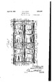
- Figure 1 is a sectional view in elevation of a machine embodying features of the present invention.
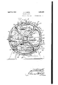
- Figure 2 is a sectional view in elevation taken substantially along line IIII of Figure 1.
- Figure 3 is a sectional view of a container used in conjunction with the machine disclosed in Figure 1.
- Figure 4 is a side view in elevation of the container shown in Figure 3.
- Figure 5 is a fragmentary view of the container shown in Figure 4, viewed substantially from line V-V of Figure 4.
- Figure 6 is a fragmentary view of a container showing a lock construction constituting means whereby the containers are secured to the rotor of the machine.
- Figure 7 is a sectional view taken substantially along line VII-VII of Figure 6.
- the structure selected for illustration comprises a cylindrical casing 10 having circular end closures 11 which are centrally apertured to receive axially aligned bearings 12 comprising part of the casing supports 13 to which the standards 14 are secured in any appropriate manner for elevating the casing from the floor or other structure upon which the standards rest.
- the casing 10 may be composed of any suitable material, preferably of Monel metal which is non-corroding, unaffected by cleansing fluids, and possesses the required strength.
- a drive shaft 15 extends through the casing 10, it being journalled in the bearings 12 W a which projectsbeyond the bearing 12.
- spur gear 16 meshes with a inion 17 which is fixed to a shaft 18 journal ed in appropriate bearings 19' and 20 preferably in rigid association with the casingv supports 14 at either end of the casing 10, thereby rigidly supportin the shaft 18 which is connected to any suitab e source of ower such as an electric motor (not. shown)
- the casing 10 may be of any desired length to accommodate any number of containers in tandem, in this instance two, the individual containers being spaced about the shaft 15 in a manner hereinafter described.
- the shaft 15 constitutin a part of the rotor, is provided with space shoulder-s19, 20, 21, and 22, to which the parallel spaced, confronting discs 23, 24, 25, and 26, respectively, are keyed or otherwise secured to constitute confining members for the containers to be described hereinafter.
- the discs 23, 24, 25, and 26, are apertured at spaced points about the axis thereof as at 27 to define radially projecting ribs or arms 28, in this instance, four thereby materially lightening the construction without impairing the strength thereof.
- the tubular members 29 and 30, preferably of non-corrodingmetal which are secured at their extremities to the shoulders 19 and 20, 21 and 22, respectively, in any appropriate manner.
- the tubes 29 and 30 are preferably hermetically sealed to the shoulders to prevent the fluid contained in the casing 10 from reaching the shaft 15 along which it would otherwise flow and find its way through the bearings 12.
- the discs 23-24 and 25-26 receivethe containers 32 therebetween, in this instance eight, which are spaced about the driving shaft 15 in operative connection therewith owing to the strips 31 which maintain the containers in spaced relation for movement in unison with the 'rotor..
- the containers in this instance, are provided with inclined radially disposed sides 33 and 34 preferably of solid metallic construction which are joined at their converging extremities by a substantially fiat member 35 disposed normal to the bisector of the angle defined by the inclined sides, the member 35 contacting with the tubular members 29 (r 30 which envelops the shaft 15.
- diverging extremities of the sides 33 and 34 terminate in parallel spaced apertured portions 36, in this instance dis osed normal the side 35 thereof and exten g substanfiaL 1y to the periphery of the discs 23-24 and 25-26, between which they are confined.
- the portions 36 have an arcuate apertured closure 37 associated therewith, the curvature thereof conforming. with the periphery of the discs to which the containers are selectively locked to prevent outward movement occasioned by the action of cmtrifugal force in consequence of the rotary movement imparted thereto.
- the end walls 38 and 39 of the containers 32 are also of solid metallic construction, they being secured to the component parts of the container in any suitable manner'such as by means of the angular members 40 constituting reinforcing edges therefor.
- An inclined wall 33 of the container 32 ispreferably hinged to the portion 36 thereof as at 41 in the usual manner, the opposed side thereof being provided with a lock 42 of standard construction whereby each container may be provided with different locks to prevent the unauthorized opening thereof or the placing of clothes in the wrong bag for delivery, since it is proposed to have a key individual to each customer.
- the locking means employed for preventing outward movement of the containers during the rotation thereof comprises a plate 43 riveted or otherwise secured to the apertured side 37, in this instance along a median line thereof, adjacent the end walls 38 and 39.
- the plate 43 has a depressed portion 44 wherein a slidable lock bolt 45 is mounted to normally project outwardly by the action of an appropriate spring 46 interposed between an abutment 47 integral with the depressed portion 44, and the shank 48 of the bolt 45 which has a portion 49 projecting above the abutment 47 to prevent the spring from moving upwardly.
- the lock bolt 45 projects through the end wall and reinforcing edge 40 of the container, it being lodged in a suitable slot 50 provided in the discs 23- 24 and 25-26 which confine the containers 32 therebetween.
- a handle 51 is pivotally mounted in the depressed-portion 44 of the plate 43 by means of a pin 52, there being a slot 53 in the bolt 45 wherein the angularly disposed extremity 54 of the handle 51 projects so as to cam the lock bolt 46 inwardly against the action of the spring when the handle 51 is pulled upwardly, thereby releasing the contained from the rotor responsive to movement of the handles occasioned by exerting a lift ing pull thereon.
- each container 32 is provided with two such lock-. ing instrumentalities arranged along a the median line or the arcuate side 37 adjacent the ends 39 and 40 thereof to engage the discs 2324 or 25126 between which they are confined.
- the containers 32 are freely removable through an opening 55 provided in the casing 10, which is of such size as to permit the containers to be individually removable therethrough.
- a closure 56 is slidably mounted on the interior of the casing to be selectively movable to cover the opening 55 which, in this instance, is disposed at the top of the easing 10'.
- the closure 56 of the casing 10 may be conveniently-removed by grasping the handle 51 thereof to lift the particular container through the opening 55 whereupon the locking bolt 45 is instantly retracted to permit the removal of the container from the confining sides 23 and 24 or 25 and 26.
- partitions 65, 66, 67, 68 and 69 wh ch extend upwardly for a distance nearly approaching the horizontal diameter of the casing 10, the partitions terminating in a horizontally disposed edge 70 having an intermediate arcuate recessed portion 71 conforming in curvature to the arcuate surface 63 of the spacing block 62 which approach each'other in confronting relation, which may, if desired, be in frictional contact, should commercial practice dictate; however, it has been found that this is not necessaryto effectively segregate the casing 10' into separate cleansing fluid compartments.
- the partitions are spaced to project within the raceways 60 and 61 defined by the spaced compartments constituting the containers 32, the partition 67 in the present embodiment, segregating the casing 10 into two portions of equal size so that two batteries of containers may be arranged in tandem as described above.
- a circular spacing block 72' is secured intermediate the discs 24 and 25 to the axis thereof to co-operate with the partition extremity 67 to prevent intermingling of the cleansing fluids contained in adjacent fluid compartments defined by the part tion 67 in much the same manner as do the spacing blocks 62 interposed between the compartments of each container.
- each customers clothes may be washed in an individual container having compartments arranged to receive the various classes of clothes which are subjected to different fluids most effective for cleansing them, there be ng no intercommunication between the fluid compartments provided within the casing 10 owing to the novel arrangement of parts above described.
- the casing 10 may be made of such size as to accommodate any number of container batteries in tandem, and each container may be varied in size and angularity so that any number may be arranged about the driving shaft to accommodate suflicient containers to suit the needs of a commercial laundry.
- each compartment is brought into a position wherein one of its parallel sides 36 is disposed .so as to face the fluid in the bottom of the cylindrical casing 10. Continued rotation of the shaft results in this perforated side 36 being forced downwardly into the fluid, re-
- an inlet pipe 72 is connected to each fluid compartment of the casing 10 in any suitable manner, it being properly valved to control admission from the supply source to which they are connected. Discharge is efl'ected through pipes 73 which communicate with the bottom of each fluid compartment so as to enable them to be selectively emptied, the used cleansing fluid be- 7 ing directed to a filtering plant or sewer as may-be found desirable.
- An overflow drain 7 4 is disposed above the supply pipe 72, at the desired liquid level so as to prevent the admission of a quantity of fluid reater than that which is compatible with e 'cient operation.
- a container for a washing machine comprising'movable closure means, radially disposed sides inclined toward each other at one end and terminating at the other end in parallel extensions having apertures therein, an arcuate apertured wall disposed between said extensions and end pieces connected to said sides.
- a container for a washing machine comprising radially disposed sides inclined toward each other at one end and terminating at the other end in parallel extensions having apertures therein, an arcuate apertured wall disposed between said extensions, end pieces connected to said sides one of said sides being hinged to constitute a closure, and locking means for said closure.
- a washing machine the combination with a casing, a driving shaft rotatabl disposed therein, a plurality of longitudinally spaced partitions connected to the periphery of said casing, said partitions extending to a point removed from said shaft, and a container rotatable by said shaft and comprising spaced compartments arranged to be positioned in said casing with the partitions projecting therebetween.
- a washing machine the combinatio with a casing, a driving shaft rotatably disosed therein, partitions fixed to said caslng, a plurality of containers spaced about said shaft, said containers comprising a plurality of spaced compartments receiving the partitions therebetween, and means radiatlng from said shaft for separating and revolving said containers in unison with said shaft 5.
- a washin machine the combination with a casing, a riving shaft rotatably disposed therein, partitions fixed to said casing, a plurality of containers spaced about said shaft, said containers comprising a plurality of spaced compartments receiving the partitions therebetween, means radiating from said shaft for separating and revolving said containers in unison with said shaft, each of said compartments having apertured arcuate sides conforming in curvature with that of said casing, and means for locking said containers in said casing".
- a washing machine the combination with a casing, a driving shaft rotatably disposed therein, partitions fixed to said casmg, a pluralit of containers spaced about said shaft, sai containers comprising a plurali of spaced compartments receiving the 6 partitions therebetween, means radiating from said shaft for separating and revolving said containers in unison with said shafts, each of said compartments having apertured arcuate sides conforming in curvature with 10 that of said casing, means for locking said containers in said casing, said containers having inclined radially disposed sides, and apertured portions angularly disposed to the radial sides of the containers.
- a framework means associated with said framework for holding a plurality of cleansin fluids, a pluralit of containers removab y mounted in said ramework, each of said :0 containers being provided with a plurality of compartments, and means for effecting relative movement of the containers with re- OHARLESOSOAR REEPS.
- a casing a shaft mounted in said casing, a removable contains a s ace between saidlcompartments, each of sai compartments including sides extending' substantially radially from said shaft' perforated sides, each of which is disand pose at an angle to one of said radial sides and adjacent the inner periphery ,of the-cas-
- a contain 40 er adapted for use in a washin machine having a cross section substantia y like a se ment and being 'defined b upwardly verging sides connected at t e bottom of the container, movable closure means for said container, parallel sides connected to the u per extremities of the diverging sides a si e connecting the parallel sides, and en pieces connected to said sides, said parallel sides being each perforated to allow washing fluid to enter and leave the container during the was 01)618131011.
- a washing machine a housing, a rotatable-shaft associated with said housing, a lurallty of gogrforated containers .
- said 65 ousing each ing removably connected to and rotatable bysaid shaft and including a plurality of spaced integral com artments and a partition connected to said housin and-extendmg inwardly towards said sha so and adapted to project into a space between vloo - said compartments of each container as the containers are rotated by said shaft.
Landscapes
- Engineering & Computer Science (AREA)
- Textile Engineering (AREA)
- Detail Structures Of Washing Machines And Dryers (AREA)
Description
A ril19,1932 I c. o, RE'EPS 1,854,485
WASHING MACHINE Filed Oct. 28, 1926 SSheets-Sheet l bv m5 April 19, 1932. c, REEPS 1,854,485
WASHING MACHINE Filed Oct. 28, 1926 3 Sheets-Sheet 2 \/g I O o O "70 6 55 0 2 April 19, 1932.- Q Q REEPS 1,854,485
WASHING MACHINE Filed Oct. 28, 1926 I5 Sheets-Sheet 3 Patented Apr. 19, 1932 UNITED, STATES.
PATENT OFFICE i CHARLES OSCAR REEPS, OF CHICAGO, ILLINOIS, ASSIGNOR 1'0 THE AMERICAN LAUNDRY MACHINERY COMPANY, OF CINCINNATI, OHIO, A CORPORATION OF OHIO WASHING MACHINE v Application filed October 28, 1926. Serial No. 144,689.
This invention relates to washing machines and more particularly to clothes washers, although it may be employed with equal advantage for other purposes.
It contemplates more especially the provision of a machine capable of accommodating a plurality of containers, each of wh ch has a multiple of compartments to receive various classes of clothes therein for enabling individual treatment to each.
Numerous devices of the character mentioned have heretofore been proposed, but these have not proven entirely satisfactory due to the inability of removing each customers washing in bulk with the container as well as to afford individual treatment to each class of clothes. This is necessary or at least highly desirable in order to procure the best and most satisfactory results both from a standpoint of cleansing and mechanical efliciency.
Further, known appliances necessitate much labor, which not only is expensive but also unsatisfactory for the reason that they require a great deal of preliminary clothes sorting with identification markings applied thereto, which gives rise to frequent mistakes and losses resulting from unauthorized taking.
One object of the present invention is to simplify the construction and improve the operation of devices of the character mentioned.
Another object is to provide means for accommodating a plurality of freely removable containers wherein each customers clothes is individually handled and cleansed. 7
Still another object is to provide a container having multiple compartments insertable as a unit'in a machine capable of receiving a plurality of such containers.
A further object is to provide a machine wherein numerous batches of clothes may be washed in individual containers which are freely removable therefrom.
A still further object is to provide a ma chine wherein numerous batches of clothes may be washed in individual containers which have the contents thereof divided into compartments, eachbeing subjected to a particular cleansing fluid.
'Other objects and advantages will appear from the following description of an illustrated embodiment of the present invention.
In the drawings:
Figure 1 is a sectional view in elevation of a machine embodying features of the present invention.
Figure 2 is a sectional view in elevation taken substantially along line IIII of Figure 1.
Figure 3 is a sectional view of a container used in conjunction with the machine disclosed in Figure 1.
Figure 4 is a side view in elevation of the container shown in Figure 3.
Figure 5 is a fragmentary view of the container shown in Figure 4, viewed substantially from line V-V of Figure 4.
Figure 6 is a fragmentary view of a container showing a lock construction constituting means whereby the containers are secured to the rotor of the machine.
Figure 7 is a sectional view taken substantially along line VII-VII of Figure 6.
The structure selected for illustration comprises a cylindrical casing 10 having circular end closures 11 which are centrally apertured to receive axially aligned bearings 12 comprising part of the casing supports 13 to which the standards 14 are secured in any appropriate manner for elevating the casing from the floor or other structure upon which the standards rest. It is to be noted that the casing 10 may be composed of any suitable material, preferably of Monel metal which is non-corroding, unaffected by cleansing fluids, and possesses the required strength.
' A drive shaft 15 extends through the casing 10, it being journalled in the bearings 12 W a which projectsbeyond the bearing 12. The
As shown, the shaft 15 constitutin a part of the rotor, is provided with space shoulder-s19, 20, 21, and 22, to which the parallel spaced, confronting discs 23, 24, 25, and 26, respectively, are keyed or otherwise secured to constitute confining members for the containers to be described hereinafter. The discs 23, 24, 25, and 26, are apertured at spaced points about the axis thereof as at 27 to define radially projecting ribs or arms 28, in this instance, four thereby materially lightening the construction without impairing the strength thereof. Surrounding the shaft 15 intermediate the discs 23 and 24, 25 and 26, are the tubular members 29 and 30, preferably of non-corrodingmetal, which are secured at their extremities to the shoulders 19 and 20, 21 and 22, respectively, in any appropriate manner. The tubes 29 and 30 are preferably hermetically sealed to the shoulders to prevent the fluid contained in the casing 10 from reaching the shaft 15 along which it would otherwise flow and find its way through the bearings 12. Secured to the confronting faces of the radially disposed ribs 28 constituting part of the discs, are the laterally projecting members or strips 31, which extend radially between the members 29 and 30 to the periphery of the discs 23-24 and 25-26. The discs 23-24 and 25-26 receivethe containers 32 therebetween, in this instance eight, which are spaced about the driving shaft 15 in operative connection therewith owing to the strips 31 which maintain the containers in spaced relation for movement in unison with the 'rotor..
The containers, in this instance, are provided with inclined radially disposed sides 33 and 34 preferably of solid metallic construction which are joined at their converging extremities by a substantially fiat member 35 disposed normal to the bisector of the angle defined by the inclined sides, the member 35 contacting with the tubular members 29 (r 30 which envelops the shaft 15. The
. diverging extremities of the sides 33 and 34 terminate in parallel spaced apertured portions 36, in this instance dis osed normal the side 35 thereof and exten g substanfiaL 1y to the periphery of the discs 23-24 and 25-26, between which they are confined. As shown, the portions 36 have an arcuate apertured closure 37 associated therewith, the curvature thereof conforming. with the periphery of the discs to which the containers are selectively locked to prevent outward movement occasioned by the action of cmtrifugal force in consequence of the rotary movement imparted thereto.
The end walls 38 and 39 of the containers 32 are also of solid metallic construction, they being secured to the component parts of the container in any suitable manner'such as by means of the angular members 40 constituting reinforcing edges therefor. An inclined wall 33 of the container 32ispreferably hinged to the portion 36 thereof as at 41 in the usual manner, the opposed side thereof being provided with a lock 42 of standard construction whereby each container may be provided with different locks to prevent the unauthorized opening thereof or the placing of clothes in the wrong bag for delivery, since it is proposed to have a key individual to each customer.
The locking means employed for preventing outward movement of the containers during the rotation thereof, comprises a plate 43 riveted or otherwise secured to the apertured side 37, in this instance along a median line thereof, adjacent the end walls 38 and 39. As shown, the plate 43 has a depressed portion 44 wherein a slidable lock bolt 45 is mounted to normally project outwardly by the action of an appropriate spring 46 interposed between an abutment 47 integral with the depressed portion 44, and the shank 48 of the bolt 45 which has a portion 49 projecting above the abutment 47 to prevent the spring from moving upwardly. The lock bolt 45 projects through the end wall and reinforcing edge 40 of the container, it being lodged in a suitable slot 50 provided in the discs 23- 24 and 25-26 which confine the containers 32 therebetween. To retract the bolt 45 so .as to permit the removal to the containers 32 from the rotor, a handle 51 is pivotally mounted in the depressed-portion 44 of the plate 43 by means of a pin 52, there being a slot 53 in the bolt 45 wherein the angularly disposed extremity 54 of the handle 51 projects so as to cam the lock bolt 46 inwardly against the action of the spring when the handle 51 is pulled upwardly, thereby releasing the contained from the rotor responsive to movement of the handles occasioned by exerting a lift ing pull thereon. It will be understood that the handles 51 are normally maintained within the depressed portion 44 of the plate 43 by virtue of the spring 46 which simultaneously urges the bolt 45 outwardly to locking position. In the present embodiment each container 32 is provided with two such lock-. ing instrumentalities arranged along a the median line or the arcuate side 37 adjacent the ends 39 and 40 thereof to engage the discs 2324 or 25126 between which they are confined.
The containers 32 are freely removable through an opening 55 provided in the casing 10, which is of such size as to permit the containers to be individually removable therethrough. To prevent the escape of the cleansing fluids contained in the casing 10, through the opening 55as well as to make it impossible for foreign substances to enter therethrough, a closure 56 is slidably mounted on the interior of the casing to be selectively movable to cover the opening 55 which, in this instance, is disposed at the top of the easing 10'.
With the arrangement of parts thus far' described, it will be apparent, that novel means have been provided to freely receive a plurality of individual, removable containers 32 constituting complemental circular segments arranged about a driving shaft 15 to be periodically immersed in the cleansing fluid which partially fills the casing 10. Upon rotation of the containers 32 containing clothes 56 therein, the cleansing fluid will be projected into the containers through the sides 36 andv37 thereof, the sides 36 being angularly disposed with the corresponding sides of the next succeeding container so as to present a free liquid space therebetween to force the cleansing fluid through the apertures therein responsive to the rotation thereof. This is especially-effective, since the sides 36 are disposed within the path of the fluid,
the apertures therein being somewhat larger in size than those provided in the arcuate end .closure 37 thereof.
Obviously, by moving the closure 56 of the casing 10 to its open position, and stopping the rotation of the containers 32, the latter may be conveniently-removed by grasping the handle 51 thereof to lift the particular container through the opening 55 whereupon the locking bolt 45 is instantly retracted to permit the removal of the container from the confining sides 23 and 24 or 25 and 26.
It has long been the practice to sort the various batches of clothes belonging to each customer into various classes to enable each to be subjected to a different cleansing treatment. In practice, it has been found that the division usually consists of three classes comprising clothes which may appropriately be classified as light, light color, and dark color, which classification is according to colors and texture. Assuming that three classes will suflice, it is the purpose of this invention to divide each container into a plurality of compartments wherein the various classes of clothes may be subjected to individual treating. shaft 15. The spacmg blocks 62 have an arcuate surface 63, and are held rigid with the compartments by means of rivets or other suitable fasteners 64, it being understood that each compartment has a hinged closure 33 as described in connection with the container 32, supra.
Fixed to the interior'of the casing 10 in any appropriate manner are partitions 65, 66, 67, 68 and 69 wh ch, in this instance, extend upwardly for a distance nearly approaching the horizontal diameter of the casing 10, the partitions terminating in a horizontally disposed edge 70 having an intermediate arcuate recessed portion 71 conforming in curvature to the arcuate surface 63 of the spacing block 62 which approach each'other in confronting relation, which may, if desired, be in frictional contact, should commercial practice dictate; however, it has been found that this is not necessaryto effectively segregate the casing 10' into separate cleansing fluid compartments. With th s arrangement, the partitions are spaced to project within the raceways 60 and 61 defined by the spaced compartments constituting the containers 32, the partition 67 in the present embodiment, segregating the casing 10 into two portions of equal size so that two batteries of containers may be arranged in tandem as described above. A circular spacing block 72' is secured intermediate the discs 24 and 25 to the axis thereof to co-operate with the partition extremity 67 to prevent intermingling of the cleansing fluids contained in adjacent fluid compartments defined by the part tion 67 in much the same manner as do the spacing blocks 62 interposed between the compartments of each container.
With this arrangement of parts it will be apparent that each customers clothes may be washed in an individual container having compartments arranged to receive the various classes of clothes which are subjected to different fluids most effective for cleansing them, there be ng no intercommunication between the fluid compartments provided within the casing 10 owing to the novel arrangement of parts above described. Obviously, the casing 10 may be made of such size as to accommodate any number of container batteries in tandem, and each container may be varied in size and angularity so that any number may be arranged about the driving shaft to accommodate suflicient containers to suit the needs of a commercial laundry.
It will be evident from Figure 3 that the perforations in the upper side 37 of eachcompartment are substantially smaller than the compartment afl'ord substantially the sole means for the washing fluid to enter and leave the compartment. From Figure 2 it will be evident that as the shaft rotates, each compartment is brought into a position wherein one of its parallel sides 36 is disposed .so as to face the fluid in the bottom of the cylindrical casing 10. Continued rotation of the shaft results in this perforated side 36 being forced downwardly into the fluid, re-
-. sulting in the fluid entering the compartment with a terrific -force. It is this feature which enables the machine of my invention to .wash clothes in much less time than any other washing machine which I have comein contact with.
After the compartment has moved through the fluid in the bottom of the casing, its other parallel and perforated side 36 is brought into a position wherein it leaves the surface of the fluid in the casing. It is while the compartment is in this position that the liquid tends to leave the compartment. However, it is to be noted that due to the clothes resting on the side 36 of the compartment adj acent the fluid, considerable of the wash ng fluid is retained in the compartment so that as it travels upwardly around the axis of shaft 15, the clothes are still being washed in fluid. Now it will be evident from the illustration in Figure 2 that the clothes 56 in any one comtime.
To facilitate the convenient admission and discharge of the flu ds, an inlet pipe 72 is connected to each fluid compartment of the casing 10 in any suitable manner, it being properly valved to control admission from the supply source to which they are connected. Discharge is efl'ected through pipes 73 which communicate with the bottom of each fluid compartment so as to enable them to be selectively emptied, the used cleansing fluid be- 7 ing directed to a filtering plant or sewer as may-be found desirable. An overflow drain 7 4 is disposed above the supply pipe 72, at the desired liquid level so as to prevent the admission of a quantity of fluid reater than that which is compatible with e 'cient operation.
I am aware that many changes may be made and numerous details of the construction may be varied through a wide range without departing from the principles of this invention, and I therefore do not pur ose limiting the patent granted hereon, ot erwise than necessitated by the prior art.
I claim as my invention:
1. A container for a washing machine, comprising'movable closure means, radially disposed sides inclined toward each other at one end and terminating at the other end in parallel extensions having apertures therein, an arcuate apertured wall disposed between said extensions and end pieces connected to said sides.
2. A container for a washing machine, comprising radially disposed sides inclined toward each other at one end and terminating at the other end in parallel extensions having apertures therein, an arcuate apertured wall disposed between said extensions, end pieces connected to said sides one of said sides being hinged to constitute a closure, and locking means for said closure.
' 3. In a washing machine, the combination with a casing, a driving shaft rotatabl disposed therein, a plurality of longitudinally spaced partitions connected to the periphery of said casing, said partitions extending to a point removed from said shaft, and a container rotatable by said shaft and comprising spaced compartments arranged to be positioned in said casing with the partitions projecting therebetween. 4. In a washing machine, the combinatio with a casing, a driving shaft rotatably disosed therein, partitions fixed to said caslng, a plurality of containers spaced about said shaft, said containers comprising a plurality of spaced compartments receiving the partitions therebetween, and means radiatlng from said shaft for separating and revolving said containers in unison with said shaft 5. In a washin machine, the combination with a casing, a riving shaft rotatably disposed therein, partitions fixed to said casing, a plurality of containers spaced about said shaft, said containers comprising a plurality of spaced compartments receiving the partitions therebetween, means radiating from said shaft for separating and revolving said containers in unison with said shaft, each of said compartments having apertured arcuate sides conforming in curvature with that of said casing, and means for locking said containers in said casing".
6. In a washing machine, the combination with a casing, a driving shaft rotatably disposed therein, partitions fixed to said casmg, a pluralit of containers spaced about said shaft, sai containers comprising a plurali of spaced compartments receiving the 6 partitions therebetween, means radiating from said shaft for separating and revolving said containers in unison with said shafts, each of said compartments having apertured arcuate sides conforming in curvature with 10 that of said casing, means for locking said containers in said casing, said containers having inclined radially disposed sides, and apertured portions angularly disposed to the radial sides of the containers.
7. In a device of the character described, a framework, means associated with said framework for holding a plurality of cleansin fluids, a pluralit of containers removab y mounted in said ramework, each of said :0 containers being provided with a plurality of compartments, and means for effecting relative movement of the containers with re- OHARLESOSOAR REEPS. I
spect to the framework to simultaneously sub 'ect each compartment of one'container to B a different cleansing fluid. 4
8. In a washing machine, a casing, a shaft mounted in said casing, a removable contains a s ace between saidlcompartments, each of sai compartments including sides extending' substantially radially from said shaft' perforated sides, each of which is disand pose at an angle to one of said radial sides and adjacent the inner periphery ,of the-cas- As an article of manufacture, a contain 40 er adapted for use in a washin machine having a cross section substantia y like a se ment and being 'defined b upwardly verging sides connected at t e bottom of the container, movable closure means for said container, parallel sides connected to the u per extremities of the diverging sides a si e connecting the parallel sides, and en pieces connected to said sides, said parallel sides being each perforated to allow washing fluid to enter and leave the container during the was 01)618131011.
10. a washing machine, a housing, a rotatable-shaft associated with said housing, a lurallty of gogrforated containers .in said 65 ousing, each ing removably connected to and rotatable bysaid shaft and including a plurality of spaced integral com artments and a partition connected to said housin and-extendmg inwardly towards said sha so and adapted to project into a space between vloo - said compartments of each container as the containers are rotated by said shaft.
11. As an article of manufacture, a con- M tainer for B in laundry machines of the eomprim'ng diverging sides
Priority Applications (1)
| Application Number | Priority Date | Filing Date | Title |
|---|---|---|---|
| US144669A US1854485A (en) | 1926-10-28 | 1926-10-28 | Washing machine |
Applications Claiming Priority (1)
| Application Number | Priority Date | Filing Date | Title |
|---|---|---|---|
| US144669A US1854485A (en) | 1926-10-28 | 1926-10-28 | Washing machine |
Publications (1)
| Publication Number | Publication Date |
|---|---|
| US1854485A true US1854485A (en) | 1932-04-19 |
Family
ID=22509605
Family Applications (1)
| Application Number | Title | Priority Date | Filing Date |
|---|---|---|---|
| US144669A Expired - Lifetime US1854485A (en) | 1926-10-28 | 1926-10-28 | Washing machine |
Country Status (1)
| Country | Link |
|---|---|
| US (1) | US1854485A (en) |
Cited By (3)
| Publication number | Priority date | Publication date | Assignee | Title |
|---|---|---|---|---|
| US2700287A (en) * | 1949-03-28 | 1955-01-25 | Sulzmann Erich | Continuous flow washing machine assembly |
| US3035430A (en) * | 1957-03-26 | 1962-05-22 | Rothenberger Jakob | Washing machine with at least two horizontal drums |
| EP0050395A1 (en) * | 1980-10-21 | 1982-04-28 | E.M. D' Hooge N.V. | Apparatus for treating textiles, such as laundry |
-
1926
- 1926-10-28 US US144669A patent/US1854485A/en not_active Expired - Lifetime
Cited By (3)
| Publication number | Priority date | Publication date | Assignee | Title |
|---|---|---|---|---|
| US2700287A (en) * | 1949-03-28 | 1955-01-25 | Sulzmann Erich | Continuous flow washing machine assembly |
| US3035430A (en) * | 1957-03-26 | 1962-05-22 | Rothenberger Jakob | Washing machine with at least two horizontal drums |
| EP0050395A1 (en) * | 1980-10-21 | 1982-04-28 | E.M. D' Hooge N.V. | Apparatus for treating textiles, such as laundry |
Similar Documents
| Publication | Publication Date | Title |
|---|---|---|
| US2296257A (en) | Apparatus for washing fabrics or the like | |
| US1854485A (en) | Washing machine | |
| US2344982A (en) | Method oe washing | |
| US2962886A (en) | Washing apparatus having filtering means | |
| US2056803A (en) | Clothes washing machine | |
| US3051457A (en) | Cleaning tank closure apparatus | |
| US1566312A (en) | Washing machine | |
| US2283612A (en) | Apparatus for washing, extracting, and drying | |
| US1991803A (en) | Laundry machinery | |
| US2887354A (en) | Washing, loading and extracting machine | |
| US2683535A (en) | Rotatable tub assembly for washing machines | |
| US2573103A (en) | Unloading structure for garment cylinders | |
| US2875602A (en) | Heavy duty washing and dry cleaning machine | |
| US1988612A (en) | Method and apparatus for separating solids from liquids | |
| US2167147A (en) | Compartmental washing machine | |
| US2313225A (en) | Dry cleaning machine | |
| US2351198A (en) | Machine for cleaning fur | |
| US1548655A (en) | Washing apparatus | |
| US2051014A (en) | Washing machine | |
| US1650592A (en) | Concrete mixer | |
| US192027A (en) | Improvement in washing-machines | |
| US2112225A (en) | Laundry apparatus | |
| US1840693A (en) | Centrifugal drying machine | |
| US1760796A (en) | Machine for treating hides, skins, leather, and other similar pieces of work | |
| US1780210A (en) | Laundry apparatus |