US1854447A - Polyphase motor control system - Google Patents
Polyphase motor control system Download PDFInfo
- Publication number
- US1854447A US1854447A US452364A US45236430A US1854447A US 1854447 A US1854447 A US 1854447A US 452364 A US452364 A US 452364A US 45236430 A US45236430 A US 45236430A US 1854447 A US1854447 A US 1854447A
- Authority
- US
- United States
- Prior art keywords
- rotor
- circuit
- windings
- condensers
- polyphase
- Prior art date
- Legal status (The legal status is an assumption and is not a legal conclusion. Google has not performed a legal analysis and makes no representation as to the accuracy of the status listed.)
- Expired - Lifetime
Links
Images
Classifications
-
- H—ELECTRICITY
- H02—GENERATION; CONVERSION OR DISTRIBUTION OF ELECTRIC POWER
- H02J—ELECTRIC POWER NETWORKS; CIRCUIT ARRANGEMENTS OR SYSTEMS FOR SUPPLYING OR DISTRIBUTING ELECTRIC POWER; SYSTEMS FOR STORING ELECTRIC ENERGY
- H02J3/00—Circuit arrangements for AC mains or AC distribution networks
- H02J3/18—Arrangements for adjusting, eliminating or compensating reactive power in networks
- H02J3/1892—Arrangements for adjusting, eliminating or compensating reactive power in networks the arrangements being an integral part of the loads or of their control circuits
Definitions
- My invention relates broadly to polyphase induction motors and more particularly to means for controlling the power factor in accordance withchanges in load or variation in speed.
- One of the objects of my invention is to provide "a circuit arrangement for a polyphase induction motor system whereby the power factor may be controlled as the load or speed varies, aminimum number of leads being taken from the rotor winding throu h slip rings for accomplishing the control in the apparatus of my invention.
- Another object of my invention is to provide a circuit arrangement for the windings of an induction motor whereby connections maybe takeh'through a system of slip rings to an external condenser circuit, the effective capacity of the several condensers in the condenser circuit being controlled according to the speed of the apparatus and in accordance with variations in the load.
- a further object of my invention is to provide a system of connections for a polyphase induction motor in which a phantom connection point is established with respect to points of diflerent relative potentials in the rotor circuit for completing connections to an external condenser system, the capacities of which are selectively varied in shunt with the several phases of the motor system according to variations in speed or load.
- FIG. 1 diagrammatically shows a polyphase induction motor system embodying the circuit arrangement of my invention
- Fig. 2 is a fragmentary diagrammatic view showin a modified form of connection for establis ing a phantom connecting point intermediate the several windings on the wound 1930.
- Fig. 3 shows a further modified form of polyphase induction motor circuit
- Fig. 4 is a fragmentary dia rammatic representation of further modi ed form of connection for establishing a phantom point in the rotor for the connection of the external capacity circuits thereto.
- reference character 1 designates the wound r0- er of a polyphase induction motor having indings 7 8 and 9 connected in delta in three phase manner and havin resistance units 4, 5 and 6 star connected etween the common points of the windings 7, 8 and 9.
- the field windings for the polyphase motor are shown at 16, 17 and 1 8.
- the centers of the resistors 4, 5 and 6 are bonded as shown at 20 and a connection taken therefrom as represented at 21 to the sli ring 22 which 23 of the poly is carried by the rotary sha phase motor.
- Shaft 23 also carries slip 'rin 10, 11 and 12 which connect respective y with the delta connected ends of the wind ings 7, 8 and 9 of the motor.
- the shaft 23 carries bevel gear 24 which meshes with bevel gear 25 forrotatively driving the centrifugal governor 26.
- the sleeve 27 on the centrifugal governor 26 controls the position of arm 28 which is adapted to be moved vertically in the guide sleeve 29.
- the link 30 is moved by arm 28 and serves to angularly shift the arm 31 for imparting corresponding angular movement to the switch system 32.
- the switch system 32 has arms 32a, 32b and 320 which are simultaneously shifted for opening the shunt connection across sets of contacts illustrated at 33a, 33b, and 330.
- the sets of contacts 33a, 33b and 330 connect to taps in the condensers 13, 14 and 15.
- the arins 32a, 32b and 320 are shifted counter-clockwise operating to disconnect the number of sections in condensers 13, 14 and 15 which are shunted by the overlapping relation of the contact arms with respect to the sets of contacts 33a, 33b and 330, thus decreasing the condenser capacity.
- the switch s stem 32 is connected through lead 34 with rush 35 which establishes wiping contact with slip rin 22.
- the connection 36 extends from one si e of condenser 13 to the brush 37 which establishes wiping contact with slip rin 10.
- connection 38 leads from one si e of condenser 14 to brush 39 which slidably engages'the sli ring 11.
- the lead 40 extends from one side of condenser and connects to brush 41 which is in sliding en agement with slip ring 12.
- I may provide a star connection and resistor elements from the mid-point of the rotor'windings 7, 8 and 9 as illustrated in Fig. 2. In this arrangement the resistors 4, 5 and 6 connect to the midpoint of windings 7, 8 and 9 and the common onded connection shown.
- e optimum oint in the winding for each phase is locate for the connection of the resistor elements 4, 5 and 6 thereto.
- Fig. 3 shows a modified circuit arrangement for the motor control system wherein inductances 44, 45 and 46 are star connected between the apex portions of the delta connected inductances 7, 8 and 9 which form the rotor windings.
- a set of slip rings similar to the slip rings described in igs. 1 and 2 are connected to the polyphase motor windings in a manner similar to the arrangement heretofore described.
- the inductance elements 44, 45 and 46 are not rotor windings.
- the centrifugal switch has been shown as including a single switch arm 42 movable over sets of contacts 43 which connect to the several sets of condenser plates of condensers 13 14 and 15 in parallel. That is to say, instead of roviding individual sets of contacts over which the switching system operates, I conneot the sets of condenser plates in arallel and render eflective successive sets 0 lates in each condenser in accordance wit the movement of arm 42. Condensers 13, 14 and 15 have the sides of o posite potential thereof connected to the brushes 37, 39 and 41 bearin upon collector rings 10, 11 and 12.
- Vhen inductance elements 44, 45 and 46 are employed, as illustrated in Fig. 3, in obtaining a phantom connected point with respect to the several windings of the rotor in lieu of the resistance elements, the inductances are made of a sizesubstantially equal to the times the inductance of each phase of the rotor (assuming that the inductance of each phase of the rotor is considered independent In the arrangement illustrated in Fig. 4 the value of the inductance in each leg of the star or Y connected circuit withinthe delta connection is less than the value of the inductance per phase of the rotor. The inductance of the rotor varies with speed in some degree.
- the centrifugal switch employed in the rotor control system operates with very small inertia and control 0 power factor by change in capacit in the circuits interconnectin the rotor win ings is promptly efiected.
- e position of the centrifugal switches shown in Fi 1 is such as to include the maximum capacity of all of the condensers in circuit with the rotor windings. This is a condition where the rotor is at rest. As the rotor speeds up the capacity in circuit with the automatically reduced and in this way the power factor is maintained substantially constant.
- the reduction in thevalue of the flux is relatively small so that at full quired a power component in quired voltage is require rotor winding is III load a magnetizing current is still reto produce the revolving field while (phase with the refor the load.
- the Q actual power POWGI' factor W EI cos a EI COS a
- the power factor of an induction motor is the value of cos a, that is, the angle between the voltage and current vectors.
- a delta connected rotor circuit In a polyphase motor, a delta connected rotor circuit, a condenser connected to each phase winding of the delta connected rotor circuit, a centrifugal switch governed by the speed of rotation of the rotor of said polyphase motor for varying the effective capacity of the condenser connected with each phase winding of the delta connected rotor and a Y connected impedance circuithaving connections extending to said delta connected rotor circuit for equalizing the distribution of current from the individual condensers through the windings of the rotor.
- a polyphase motor control system com-- prising a rotor having delta connected windings, collector rings connected to each of said windings, a multiplicity of impedance elements connected in Y and connected to the several phase windings of said rotor, a collector ring connected with each of the windings in the delta connected rotor, an auxiliary collector ring connected to the common point in the star connected impedance circuit which connects with said rotor windings, a condenser connected to each of the collector rings in circuit with the several phase windings of said rotor circuit, a return circuit extending from the opposite sides of each of said condensers and said auxiliary collector ring, and centrifu a1 means for varying the effective value of t e capacity of each of said condensers connected with each of the phase windings of said rotor.
- a control system for polyphase motors comprising a polyphase wound rotor, collector rings connected to points in said wound rotor, a condenser connected with each of said collect-or rings, centrifugal means for varying the effective value of each of said condensers according to the speed of rotation of said rotor, and an impedance circuit for establishing connection between all of said condensers and points in said wound rotor whereby the capacity in circuit with each of said windings of the rotor ma be selectively varied in accordance with tile speed of said rotor.
- a polyphase motor control circuit comprising a delta connected wound rotor, collector rings connected to each phase winding of said wound rotor, a Y connected impedance circuit connected with points in the circuit of said rotor, condensers connected with each of said collector rings, said-condensers each being variable according to the speed of said rotor, circuits extending between said collector rings and each of said condensers, and a connection between a mid-point in said Yconnected impedance circuit with said condensers whereby the capacity effective across each of the phase windings of said delta connected rotor may be selectively controlled.
- a polyphase motor control system including a polyphase wound rotor having separate windings in each phase thereof, co1- lector rings connected with each of the windings of said rotor, a Y connected impedance circuit connected to points in said polyphase wound rotor circuit, a collector ring connected to the neutral point of said Y connected impedance circuit, condensers in circuit with each of the collector rings connected to the windings of said polyphase motor, one side of each of said condensers being connected with a collector ring individual to each windin of said rotor circuit, and the opposite si e of each of said condensers bein connected with the neutral point in said% connected impedance circuit, and means for selectively changing the effective value of the capacit of each of the condensers connected to t e windings of said rotor according to the speed of said rotor.
- a polyphase motor control circuit comprising in combination a polyphase rotor circuit including an inductance connected with each phase thereof, collector rin s connected to each phase wlnding of'sai rotor circuit, independent condensers, connections between one side of each of said condensers and each of said collector rings, a Y connected impedance circuit havin impedance elements connected with the mid-points of the phase windings in said rotor circuit, a connection between a neutral point in said Y connected impedance circuit and the other side of each of said condensers, and means in said connection for selectively controlling the effective values of each of the condensers connected to the phase windings of said rotor circuit and operative according to the speed of said rotor.
- a polyphase motor control system comprising a rotor having a winding in each phase thereof, collector rings connected with each phase winding of said rotor, a multiplate condenser connected at one side to each of said collector rings, 'centrifu al means, a
Landscapes
- Engineering & Computer Science (AREA)
- Power Engineering (AREA)
- Control Of Ac Motors In General (AREA)
Description
April 19, 1932. r J, CHRQMY 1,854,447
POLYPHASE MOTOR CONTROL SYSTEM Fil ed May 14, 1930 o 1 INVENTOR.
.CW T? 95 6,44 5? BY J z 44 /0 ATTOREY.
8 noun.
Patented Apr. 19, 1932 PATENT OFFICE BEN J. CHROIY, OI 'KOPKIN S, MINNESOTA,
ABSIGNOB TO WIRED RADIO, INC 0] NEW YORK, N. Y A CORPORATION OF DELAWARE ronnmr. uo'ron'con'raor. sr'srmr Application filed May 14,.
My invention relates broadly to polyphase induction motors and more particularly to means for controlling the power factor in accordance withchanges in load or variation in speed.
One of the objects of my invention is to provide "a circuit arrangement for a polyphase induction motor system whereby the power factor may be controlled as the load or speed varies, aminimum number of leads being taken from the rotor winding throu h slip rings for accomplishing the control in the apparatus of my invention.
Another object of my invention is to provide a circuit arrangement for the windings of an induction motor whereby connections maybe takeh'through a system of slip rings to an external condenser circuit, the effective capacity of the several condensers in the condenser circuit being controlled according to the speed of the apparatus and in accordance with variations in the load.
A further object of my invention is to provide a system of connections for a polyphase induction motor in which a phantom connection point is established with respect to points of diflerent relative potentials in the rotor circuit for completing connections to an external condenser system, the capacities of which are selectively varied in shunt with the several phases of the motor system according to variations in speed or load.
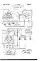
Other and further objects of my invention re side in the circuit arrangement for a polyphase induction motor as set forth more fully in the specification hereinafter following by relflerfince to the accompanying drawings, in w 1c Figure 1 diagrammatically shows a polyphase induction motor system embodying the circuit arrangement of my invention; Fig. 2 is a fragmentary diagrammatic view showin a modified form of connection for establis ing a phantom connecting point intermediate the several windings on the wound 1930. Serial H0. 452,364.
rotor of the polyphase motor; Fig. 3 shows a further modified form of polyphase induction motor circuit; and Fig. 4 is a fragmentary dia rammatic representation of further modi ed form of connection for establishing a phantom point in the rotor for the connection of the external capacity circuits thereto.
Referring to the drawings in detail reference character 1 designates the wound r0- er of a polyphase induction motor having indings 7 8 and 9 connected in delta in three phase manner and havin resistance units 4, 5 and 6 star connected etween the common points of the windings 7, 8 and 9. The field windings for the polyphase motor are shown at 16, 17 and 1 8. The centers of the resistors 4, 5 and 6 are bonded as shown at 20 and a connection taken therefrom as represented at 21 to the sli ring 22 which 23 of the poly is carried by the rotary sha phase motor. Shaft 23 also carries slip ' rin 10, 11 and 12 which connect respective y with the delta connected ends of the wind ings 7, 8 and 9 of the motor. The shaft 23 carries bevel gear 24 which meshes with bevel gear 25 forrotatively driving the centrifugal governor 26. The sleeve 27 on the centrifugal governor 26 controls the position of arm 28 which is adapted to be moved vertically in the guide sleeve 29. The link 30 is moved by arm 28 and serves to angularly shift the arm 31 for imparting corresponding angular movement to the switch system 32. The switch system 32 has arms 32a, 32b and 320 which are simultaneously shifted for opening the shunt connection across sets of contacts illustrated at 33a, 33b, and 330.-
The sets of contacts 33a, 33b and 330 connect to taps in the condensers 13, 14 and 15. As the speed increases, the arins 32a, 32b and 320 are shifted counter-clockwise operating to disconnect the number of sections in condensers 13, 14 and 15 which are shunted by the overlapping relation of the contact arms with respect to the sets of contacts 33a, 33b and 330, thus decreasing the condenser capacity. The switch s stem 32 is connected through lead 34 with rush 35 which establishes wiping contact with slip rin 22. The connection 36 extends from one si e of condenser 13 to the brush 37 which establishes wiping contact with slip rin 10. The connection 38 leads from one si e of condenser 14 to brush 39 which slidably engages'the sli ring 11. The lead 40 extends from one side of condenser and connects to brush 41 which is in sliding en agement with slip ring 12. In lieu of the p antom connection provided by the resistance elements 4, 5 and 6 on the rotor of the induction motor extending between the apex connections of the rotor windings 7, 8 and 9, I may provide a star connection and resistor elements from the mid-point of the rotor'windings 7, 8 and 9 as illustrated in Fig. 2. In this arrangement the resistors 4, 5 and 6 connect to the midpoint of windings 7, 8 and 9 and the common onded connection shown. at connects to the slip ring 22 in the manner illustrated in Fig. 1. The apex portions of the delta ar- 2 when t ranged rotor windings connect to slip rings 10, 11 and 12 as illustrated. A substantially better in'terbalancing of the phases is obtained by the connections illustrated in Fig.
e optimum oint in the winding for each phase is locate for the connection of the resistor elements 4, 5 and 6 thereto.
Fig. 3 shows a modified circuit arrangement for the motor control system wherein inductances 44, 45 and 46 are star connected between the apex portions of the delta connected inductances 7, 8 and 9 which form the rotor windings. A set of slip rings similar to the slip rings described in igs. 1 and 2 are connected to the polyphase motor windings in a manner similar to the arrangement heretofore described. The inductance elements 44, 45 and 46 are not rotor windings.
but are means arranged to obtain a point 47 of substantially zero voltage with respect to the several windin s 7, 8 and 9 of the rotor. The centrifugal switch has been shown as including a single switch arm 42 movable over sets of contacts 43 which connect to the several sets of condenser plates of condensers 13 14 and 15 in parallel. That is to say, instead of roviding individual sets of contacts over which the switching system operates, I conneot the sets of condenser plates in arallel and render eflective successive sets 0 lates in each condenser in accordance wit the movement of arm 42. Condensers 13, 14 and 15 have the sides of o posite potential thereof connected to the brushes 37, 39 and 41 bearin upon collector rings 10, 11 and 12.
In 1g. 4 I have shown a star connected inductance system including the elements 44, 45 and 46 connected to midpotential points along windings 7, 8 and 9. Connections are taken from the common point 47 to sli ring 22 and from the apex points of the connected system connections are taken to the sli rings 10, 11 and 12.
As the load increases this angle'tends to increase. This is due to the increase of the reactance of the stator and rotor windings which increases with the load and the current tends to lag behind the voltage. In the system of my invention the power factor is maintained constant for the reduction in capacity in proportion to increases in speed balances the inductive reactance which increases, thereby preventing the further lag of the current vector with respect to the voltage vector. The arrangementof the star con nected impedances within the'delta connected rotor windings is such that equalized distribution of current through the capacity and inductance of the several phases is obtained.
While I have described my invention in certain preferred embodiments I desire that it be understood that modifications may be made and that no limitations upon my invention are intended other than are imposed by the scope of the appended claims.
What I claim as new and desire to secure by Letters Patent of the United States is as follows:
1. In a polyphase motor, a delta connected rotor circuit, a condenser connected to each phase winding of the delta connected rotor circuit, a centrifugal switch governed by the speed of rotation of the rotor of said polyphase motor for varying the effective capacity of the condenser connected with each phase winding of the delta connected rotor anda Y connected impedance circuithaving connections extending to said delta connected rotor circuit for equalizing the distribution of current from the individual condensers through the windings of the rotor.
- the rotor circuit, a condenser connected with each phase winding of the polyphase motor sistem, a centrifugal switch controlled by t e movement of said rotor for controlling the effective values of the condensers in circuit with the separate phase windings of said rotor, and a star connected impedance circuit'connected with said delta connected totor circuit for completing connections between said condensers and each of the wind,- ings in the separate phases of said rotor circuit.
3. A polyphase motor control system com-- prising a rotor having delta connected windings, collector rings connected to each of said windings, a multiplicity of impedance elements connected in Y and connected to the several phase windings of said rotor, a collector ring connected with each of the windings in the delta connected rotor, an auxiliary collector ring connected to the common point in the star connected impedance circuit which connects with said rotor windings, a condenser connected to each of the collector rings in circuit with the several phase windings of said rotor circuit, a return circuit extending from the opposite sides of each of said condensers and said auxiliary collector ring, and centrifu a1 means for varying the effective value of t e capacity of each of said condensers connected with each of the phase windings of said rotor.
i. A control system for polyphase motors comprising a polyphase wound rotor, collector rings connected to points in said wound rotor, a condenser connected with each of said collect-or rings, centrifugal means for varying the effective value of each of said condensers according to the speed of rotation of said rotor, and an impedance circuit for establishing connection between all of said condensers and points in said wound rotor whereby the capacity in circuit with each of said windings of the rotor ma be selectively varied in accordance with tile speed of said rotor.
5. A polyphase motor control circuit comprising a delta connected wound rotor, collector rings connected to each phase winding of said wound rotor, a Y connected impedance circuit connected with points in the circuit of said rotor, condensers connected with each of said collector rings, said-condensers each being variable according to the speed of said rotor, circuits extending between said collector rings and each of said condensers, and a connection between a mid-point in said Yconnected impedance circuit with said condensers whereby the capacity effective across each of the phase windings of said delta connected rotor may be selectively controlled.
6. A polyphase motor control system including a polyphase wound rotor having separate windings in each phase thereof, co1- lector rings connected with each of the windings of said rotor, a Y connected impedance circuit connected to points in said polyphase wound rotor circuit, a collector ring connected to the neutral point of said Y connected impedance circuit, condensers in circuit with each of the collector rings connected to the windings of said polyphase motor, one side of each of said condensers being connected with a collector ring individual to each windin of said rotor circuit, and the opposite si e of each of said condensers bein connected with the neutral point in said% connected impedance circuit, and means for selectively changing the effective value of the capacit of each of the condensers connected to t e windings of said rotor according to the speed of said rotor.
7. A polyphase motor control circuit comprising in combination a polyphase rotor circuit including an inductance connected with each phase thereof, collector rin s connected to each phase wlnding of'sai rotor circuit, independent condensers, connections between one side of each of said condensers and each of said collector rings, a Y connected impedance circuit havin impedance elements connected with the mid-points of the phase windings in said rotor circuit, a connection between a neutral point in said Y connected impedance circuit and the other side of each of said condensers, and means in said connection for selectively controlling the effective values of each of the condensers connected to the phase windings of said rotor circuit and operative according to the speed of said rotor.
8. A polyphase motor control system comprising a rotor having a winding in each phase thereof, collector rings connected with each phase winding of said rotor, a multiplate condenser connected at one side to each of said collector rings, 'centrifu al means, a
switch operative by said centri gal means for selecting the efiective number of plates of each of said condensers in circuit with said collector rings according to the speed of said rotor, and a Y connected impedance circuit having its neutral point connected in common with all of said condensers and other points therein connected with eachof the phase windings of said rotor.
In testimony whereof I aflix my si ature.
BEN J. GHR MY.
Priority Applications (1)
| Application Number | Priority Date | Filing Date | Title |
|---|---|---|---|
| US452364A US1854447A (en) | 1930-05-14 | 1930-05-14 | Polyphase motor control system |
Applications Claiming Priority (1)
| Application Number | Priority Date | Filing Date | Title |
|---|---|---|---|
| US452364A US1854447A (en) | 1930-05-14 | 1930-05-14 | Polyphase motor control system |
Publications (1)
| Publication Number | Publication Date |
|---|---|
| US1854447A true US1854447A (en) | 1932-04-19 |
Family
ID=23796182
Family Applications (1)
| Application Number | Title | Priority Date | Filing Date |
|---|---|---|---|
| US452364A Expired - Lifetime US1854447A (en) | 1930-05-14 | 1930-05-14 | Polyphase motor control system |
Country Status (1)
| Country | Link |
|---|---|
| US (1) | US1854447A (en) |
Cited By (5)
| Publication number | Priority date | Publication date | Assignee | Title |
|---|---|---|---|---|
| WO1990000833A1 (en) * | 1988-07-12 | 1990-01-25 | Heller-Dejulio Corp. | Rotary induction machine having control of secondary winding impedance |
| US5587643A (en) * | 1988-07-12 | 1996-12-24 | Heller Dejulio Corporation | Rotary induction machine having control of secondary winding impedance |
| US5986438A (en) * | 1998-04-21 | 1999-11-16 | Heller-Dejulio Corporation | Rotary induction machine having control of secondary winding impedance |
| US6331760B1 (en) * | 1998-10-06 | 2001-12-18 | Mclane, Jr. Oscar B. | Capacitive induction motor and method |
| US20030221265A1 (en) * | 2002-05-29 | 2003-12-04 | Lg Electronics Inc. | Device for controlling motor in washing machine and method for controlling process of washing machine by using the same |
-
1930
- 1930-05-14 US US452364A patent/US1854447A/en not_active Expired - Lifetime
Cited By (7)
| Publication number | Priority date | Publication date | Assignee | Title |
|---|---|---|---|---|
| WO1990000833A1 (en) * | 1988-07-12 | 1990-01-25 | Heller-Dejulio Corp. | Rotary induction machine having control of secondary winding impedance |
| US5587643A (en) * | 1988-07-12 | 1996-12-24 | Heller Dejulio Corporation | Rotary induction machine having control of secondary winding impedance |
| US5986438A (en) * | 1998-04-21 | 1999-11-16 | Heller-Dejulio Corporation | Rotary induction machine having control of secondary winding impedance |
| US6163137A (en) * | 1998-04-21 | 2000-12-19 | Heller-Dejulio Corporation | Rotary induction machine having control of secondary winding impedance |
| US6331760B1 (en) * | 1998-10-06 | 2001-12-18 | Mclane, Jr. Oscar B. | Capacitive induction motor and method |
| US20030221265A1 (en) * | 2002-05-29 | 2003-12-04 | Lg Electronics Inc. | Device for controlling motor in washing machine and method for controlling process of washing machine by using the same |
| US7299664B2 (en) * | 2002-05-29 | 2007-11-27 | Lg Electronics Inc. | Device for controlling motor in washing machine and method for controlling process of washing machine by using the same |
Similar Documents
| Publication | Publication Date | Title |
|---|---|---|
| US1854447A (en) | Polyphase motor control system | |
| US2565157A (en) | Polyphase induction motor control | |
| US1934060A (en) | Condenser motor | |
| US2120321A (en) | Electric motor | |
| US2482513A (en) | Motor control system | |
| US1189296A (en) | Variable-speed motor. | |
| US1499359A (en) | Combined frequency changer and phase converter | |
| US2094512A (en) | Capacitor motor | |
| US3150306A (en) | Multiple winding induction motor with various winding distribution factors | |
| US2608676A (en) | Induction motor control system | |
| US2091665A (en) | Capacitor motor | |
| US1273782A (en) | Electric ship propulsion. | |
| US1561146A (en) | Balanced electrostatic phase converter | |
| US1778599A (en) | Speed and power factor control of induction machines | |
| US1284293A (en) | System of distribution. | |
| US1499360A (en) | Frequency-converter method and system | |
| US3111616A (en) | Electric motor construction with various winding distribution factors | |
| US2380265A (en) | Adjustable transformer regulator | |
| US1997699A (en) | Control system | |
| US856477A (en) | Alternating-current motor. | |
| US2624028A (en) | Variable speed alternating current motor | |
| US1626622A (en) | Induction motor | |
| US1640547A (en) | Variable-speed induction-motor set | |
| US1296487A (en) | System of speed control for induction-motors. | |
| US2023237A (en) | Condenser motor |