US856477A - Alternating-current motor. - Google Patents
Alternating-current motor. Download PDFInfo
- Publication number
- US856477A US856477A US19568504A US1904195685A US856477A US 856477 A US856477 A US 856477A US 19568504 A US19568504 A US 19568504A US 1904195685 A US1904195685 A US 1904195685A US 856477 A US856477 A US 856477A
- Authority
- US
- United States
- Prior art keywords
- motor
- winding
- resistance
- starting
- running
- Prior art date
- Legal status (The legal status is an assumption and is not a legal conclusion. Google has not performed a legal analysis and makes no representation as to the accuracy of the status listed.)
- Expired - Lifetime
Links
Images
Classifications
-
- H—ELECTRICITY
- H02—GENERATION; CONVERSION OR DISTRIBUTION OF ELECTRIC POWER
- H02K—DYNAMO-ELECTRIC MACHINES
- H02K17/00—Asynchronous induction motors; Asynchronous induction generators
- H02K17/02—Asynchronous induction motors
- H02K17/04—Asynchronous induction motors for single phase current
- H02K17/06—Asynchronous induction motors for single phase current having windings arranged for permitting pole-changing
Definitions
- My invention relates. to alternating cur rent motors, and it has for its'obje'ct to pro: vide secondary windings for such motors which have high resistance under starting conditions and. relatively low resistance un-
- induction motor having a primary winding two portions of which may be connectedin series'lor starting the motor and in parallei running, the number of magnetic poles in- .d by the winding being thereby changed.
- fin auxiliary winding is also p rovided which is'either of high resistance 01 has an exterit, and is connected in parallel with the main windin starting the 'motor..
- This motor, or aryother motor using" the divided circuit split phase'arrangeinent is practically a noiyphase machine when starting and coni'nrms to the laws governing starting conditions of such motors.
- a single-phase motor such as I have referred to is a polypha'se motor at the start, it should have, for economical starting, a secondary winding of relatively high resrstlance, and for running, asecondary winding pi comparatively low resistance, in order to obtain the desired pull-out torque. It follows, therefore, that it a secondary Ytflllde ing can be so designed that it Wlll havea high resistancaunder starting conditions and a conditions of the motor,
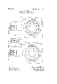
- Figures 1 and 2 represent diagrammatically the windings of induction motors constructci'l in accordance with my invention and Fig. is a diagrammatic view of the switching device in proper position for running conditions of the motor.
- the primary windings A, A, B, B and C, C of the motor 1 are connected by means of athree-pole, double-throw switch 2 for starting conditions of the motor.
- Single-phase energy is supplied to the main of the circuit from through the switchand B, B, switchblade 4, to line conductor L and to the auxiliary winding by means of the circuitirom theline conductor L switch-blade 3, windings C, C, resistance R, switch-blade 5, to .the'line conductor L NX poles are induced by this arrangement of windings, but if the switch is in the position shown in F 3, the current is reversed in the portion B, B of the main winding and X poles are then iruluct-zd by the main primary winding, the auxiliary winding G, O and its connected resistance it being thrown out of circuit.
- the secondary member the line conductor L 7 is pro- 1 vided with a winding comprising a plurality the position shown in Fig.1, the conditions" and 'no current can flow unless some-bath is furnished in addition to that in the coi -itself.'
- the switch is in the 'positionfsho-Wn in Fig-. 3,- the poles acting upon the sides 8 and 9 of the coil. will be 0 I polarity. and currentwill flow in the, coil 10, a short-circuited, low resistance, secondary circuit being thus provided for running conditions of the motor.
- FIG. 2 A modification of the above describedarrangement is showninFig. 2 and consists ing 12 is of comparatively high resistance and each of its coils has a polar span that isioneg ,The oppoactionof poles of unlike'polarity vvheillthe Each v of the coils. of. the;
- induction motor having a rotor with v a short circuit'ed Winding orwi/indings' of low '9 5 "resistance and anothershort circuited-W'inding or windings- 0f highresistance, and a stator f having a switchconnected 'to rearrange the "polarity ofits poles at startingin ar'nianner ito'cause, the sumytotalpf. electrical pressures in'the low resistance windingsito be Z61'0,'.Slll),'.
Landscapes
- Engineering & Computer Science (AREA)
- Power Engineering (AREA)
- Motor And Converter Starters (AREA)
Description
PATENTED JUNE .11, 1907.
B. G. LAMME, ALTERNATING CURRENT MOTOR.
APPLICATION FILED FEB. 27, 1904.
. WITNESSES;
INVENTOR #Zkyk, 744 M) J M W A TTORNE 1.
.amount of resistance der running conditions.
rial high. resistance in series with torque.
BENJAMIN o. Linens, orrrrrsn'ciis, PENNSYLVANIA,
ASSIGNOR TO WEST- monouss announce MANUFACTURING COMPANY, A CORPORATION- OF PEN N SYLVAN IA.
ALTERNATlNG CU RRENT MOTOR.
' Specification of Letters Patent.
Patented. June 11, 1907.
Application filed February 27,1(504. Serial No. 195,685.
.To all whom it may concern:
Be it known that I, BENJAMIN G. LAMME, a citizen of the United States, and a resident of Pittsburg, in the county of Allegheny and State of Pennsylvania, have invented a new and useful improvement in Alternating-Current Motors, of which the following is a speciiication.
My invention relates. to alternating cur rent motors, and it has for its'obje'ct to pro: vide secondary windings for such motors which have high resistance under starting conditions and. relatively low resistance un- In an application Serial by me of even date herewith, I have described an induction motor having a primary winding two portions of which may be connectedin series'lor starting the motor and in parallei running, the number of magnetic poles in- .d by the winding being thereby changed. fin auxiliary winding is also p rovided which is'either of high resistance 01 has an exterit, and is connected in parallel with the main windin starting the 'motor.. This motor, or aryother motor using" the divided circuit split phase'arrangeinent, is practically a noiyphase machine when starting and coni'nrms to the laws governing starting conditions of such motors.
It is generally understood that apolyphase motor requires ahigher resistance in its secondary winding when" starting than when running, in order to insure a large starting in a single-phase motor, it'is still more important that the secondary winding 'have' a relatiyely low resistance when running,
since the maximum torque or pull-out torque of the motor is dependent upon the in the secondary circuit, while in a polyphase motor the pull out torque is independent of the resistance.
' Since a single-phase motor such as I have referred to is a polypha'se motor at the start, it should have, for economical starting, a secondary winding of relatively high resrstlance, and for running, asecondary winding pi comparatively low resistance, in order to obtain the desired pull-out torque. It follows, therefore, that it a secondary Ytflllde ing can be so designed that it Wlll havea high resistancaunder starting conditions and a conditions of the motor,
No. rests raise" i i l l l l primary winding by means blade 3, windings-A, A
low resistance when the motor is running, without the employment of variable resist ance or short-circuiting devices, it will. fur--- msh an ideal construction for induction motors; This cannot readily be obtained it the same number of primary magnetic poles is used in starting as in running, but it the 60 number of poles in starting is different from that when running, an arrangement of sec ondary winding, provided by my present invention, can be adopted which will give circuits having different resistances for starting and running, due to the fact that the secondary circuits are different for different numbers of magnetic poles inthe primary neinber.
in the accompanying drawings, Figures 1 and 2 represent diagrammatically the windings of induction motors constructci'l in accordance with my invention and Fig. is a diagrammatic view of the switching device in proper position for running conditions of the motor.
In Figs. 1 and 2, the primary windings A, A, B, B and C, C of the motor 1 are connected by means of athree-pole, double-throw switch 2 for starting conditions of the motor. Single-phase energy is supplied to the main of the circuit from through the switchand B, B, switchblade 4, to line conductor L and to the auxiliary winding by means of the circuitirom theline conductor L switch-blade 3, windings C, C, resistance R, switch-blade 5, to .the'line conductor L NX poles are induced by this arrangement of windings, but if the switch is in the position shown in F 3, the current is reversed in the portion B, B of the main winding and X poles are then iruluct-zd by the main primary winding, the auxiliary winding G, O and its connected resistance it being thrown out of circuit.
In Fig. 1, the secondary member the line conductor L 7 is pro- 1 vided with a winding comprising a plurality the position shown in Fig.1, the conditions" and 'no current can flow unless some-bath is furnished in addition to that in the coi -itself.' However, if the switch is in the 'positionfsho-Wn in Fig-. 3,- the poles acting upon the sides 8 and 9 of the coil. will be 0 I polarity. and currentwill flow in the, coil 10, a short-circuited, low resistance, secondary circuit being thus provided for running conditions of the motor.
In order to provide secondary circuits of the proper resistance underv starting condi tions of the motor, connections may be made,
posits at each end of the short-circuited coils 10, to
11, or the proper a 1 high resistance r'ing amount ofresistancemay be included in the. connections between the ends of'the coils 1-0 and the rings 11. It Willbe understood trom the foregoing description that this'arr'ange ment of windings and connections insures lowresistance secondary circuits for running devices.
the use of two'in'dependent secondary' winding's 12 and 13, sac of which comprises a plurality ofshort-circuited coils. The Wind: s5
.5 sides are simultaneously subjected to t sinluctive action ofpoles' o1? unlike polarity'whenf the .motor is connected for running etude. tions that is, for the smaller number'of poles. that this arrangement.
It is therefore obvious also provides high resistance secondary C11;
uits-for starting and low resistancesecondarycircui-ts for running the motor.
While I have shown: and described my invention as appliedonly to single-phase mo 5 5 tors in which the ratio of the-numhersof poles for starting and for ri'inningis uniike.
numbers -of magnetic poles. an
i high resistance Whichi's eifectiyewhen conditions of the motor and resistance secondary circuitsffor. starting conditions of i the motor, and thiswithout the use of van-5 able resistance "or? external shortecircuiting A modification of the above describedarrangement is showninFig. 2 and consists ing 12 is of comparatively high resistance and each of its coils has a polar span that isioneg ,The oppoactionof poles of unlike'polarity vvheillthe Each v of the coils. of. the;
twoto one, it is to fbe understood'that itv is equally;
' applicable to-polyphase motors andith'at 'SiIill-= lar' arrangements of Winding-s are possihle motors having other ratios the numbers of .6
poles. 3 v
lclaim asimyinvention'; v a 1 in an 'a-lternatingcurrent moa the? combination With a primaryJmember hayin fl a Winding adapted to produce;rad-plurality iii- 6 5 numbers of magnetic polesi and'means for. ech'angin'g from one number to another, ot'a secondary member 'having Ea plurality of windings of different resistance that are re spectively efiective for dilferent numbers;of. 7o polesinthe'primary member. 11. 9 In an alternating current motor/the combination with a primary member havin' "a windingadapted to produce-a lurialityo meane I0 changing from; one number of poles to ans; other, '0 "a secondary member hai in a Flumay of\separate Windings',"6ne of. re atively a] r e nunihe'r'bf fnagnetic poles is induced tile" 30 primary member and the other of'which be- I comes eiiectivejwhen the srr'ialler number of niagneticjpoles-is induced; in the primary -mernberr. I
induction. motorfhaving two rotor windings or sets {of short-circuited rotor-' windings," orie .of"high resistance and the ther of low resistance, and means connected With [the 'stator'winding' for suppressing. the generation of currents in'the low resistance, Winding at starting and for-permitting the; creation" of currents when running, substan tially as described.
4 1; induction motor having a rotor with v a short circuit'ed Winding orwi/indings' of low '9 5 "resistance and anothershort circuited-W'inding or windings- 0f highresistance, and a stator f having a switchconnected 'to rearrange the "polarity ofits poles at startingin ar'nianner ito'cause, the sumytotalpf. electrical pressures in'the low resistance windingsito be Z61'0,'.Slll),'.
s'tanti'ally asdescrib'ed.
in testimony' whereof, I have hereunto subscribed my name this 12th day of: February, 1904.;
BENJ. G/LAMME.
Witnesses:
I ELISABET M, STEWART,
,Bnmnr Hnvns.
Priority Applications (1)
| Application Number | Priority Date | Filing Date | Title |
|---|---|---|---|
| US19568504A US856477A (en) | 1904-02-27 | 1904-02-27 | Alternating-current motor. |
Applications Claiming Priority (1)
| Application Number | Priority Date | Filing Date | Title |
|---|---|---|---|
| US19568504A US856477A (en) | 1904-02-27 | 1904-02-27 | Alternating-current motor. |
Publications (1)
| Publication Number | Publication Date |
|---|---|
| US856477A true US856477A (en) | 1907-06-11 |
Family
ID=2924932
Family Applications (1)
| Application Number | Title | Priority Date | Filing Date |
|---|---|---|---|
| US19568504A Expired - Lifetime US856477A (en) | 1904-02-27 | 1904-02-27 | Alternating-current motor. |
Country Status (1)
| Country | Link |
|---|---|
| US (1) | US856477A (en) |
Cited By (2)
| Publication number | Priority date | Publication date | Assignee | Title |
|---|---|---|---|---|
| US2795750A (en) * | 1950-12-26 | 1957-06-11 | Johnson Eleanor De Haas | Alternating current machinery |
| US3031606A (en) * | 1957-05-27 | 1962-04-24 | Charles R Cantouwine | Electric motor construction |
-
1904
- 1904-02-27 US US19568504A patent/US856477A/en not_active Expired - Lifetime
Cited By (2)
| Publication number | Priority date | Publication date | Assignee | Title |
|---|---|---|---|---|
| US2795750A (en) * | 1950-12-26 | 1957-06-11 | Johnson Eleanor De Haas | Alternating current machinery |
| US3031606A (en) * | 1957-05-27 | 1962-04-24 | Charles R Cantouwine | Electric motor construction |
Similar Documents
| Publication | Publication Date | Title |
|---|---|---|
| US856477A (en) | Alternating-current motor. | |
| US1123321A (en) | Method of operating polyphase induction-motors. | |
| US1934060A (en) | Condenser motor | |
| US2454136A (en) | Two-speed single-phase motor | |
| US1356933A (en) | Induction-motor | |
| US1726230A (en) | Induction motor | |
| US1879229A (en) | Power factor regulation of alternating current machines | |
| US3111616A (en) | Electric motor construction with various winding distribution factors | |
| US3264542A (en) | Multi-speed single-phase motor | |
| US1499359A (en) | Combined frequency changer and phase converter | |
| US873702A (en) | Alternating-current motor. | |
| US1552385A (en) | Asynchronous motor | |
| US1273782A (en) | Electric ship propulsion. | |
| US811644A (en) | Single-phase alternating-current motor. | |
| US888514A (en) | Armature-winding for electrical machines. | |
| US3150306A (en) | Multiple winding induction motor with various winding distribution factors | |
| US609991A (en) | Method of and means for securing constant torque in polyphase motors | |
| US1122491A (en) | Alternating-current motor. | |
| US854296A (en) | Electromotor of the induction type. | |
| US902720A (en) | Single-phase commutator-motor. | |
| USRE13638E (en) | Best available copx | |
| US1296620A (en) | Alternating-current motor. | |
| US871189A (en) | Alternating-current motor. | |
| US1570347A (en) | Converter system | |
| US1933774A (en) | Electrical motor and method of starting the same |