US185443A - Improvement in toy money-boxes - Google Patents
Improvement in toy money-boxes Download PDFInfo
- Publication number
- US185443A US185443A US185443DA US185443A US 185443 A US185443 A US 185443A US 185443D A US185443D A US 185443DA US 185443 A US185443 A US 185443A
- Authority
- US
- United States
- Prior art keywords
- rod
- plate
- lid
- catch
- coin
- Prior art date
- Legal status (The legal status is an assumption and is not a legal conclusion. Google has not performed a legal analysis and makes no representation as to the accuracy of the status listed.)
- Expired - Lifetime
Links
- 238000005192 partition Methods 0.000 description 4
- ZQWBGSZBBGYKNV-UHFFFAOYSA-N 2-(4-ethoxyphenyl)-1,3-bis(4-methoxyphenyl)guanidine;hydrochloride Chemical compound Cl.C1=CC(OCC)=CC=C1N=C(NC=1C=CC(OC)=CC=1)NC1=CC=C(OC)C=C1 ZQWBGSZBBGYKNV-UHFFFAOYSA-N 0.000 description 1
- 239000002184 metal Substances 0.000 description 1
- 238000000034 method Methods 0.000 description 1
Images

Classifications
-
- G—PHYSICS
- G07—CHECKING-DEVICES
- G07F—COIN-FREED OR LIKE APPARATUS
- G07F17/00—Coin-freed apparatus for hiring articles; Coin-freed facilities or services
- G07F17/04—Coin-freed apparatus for hiring articles; Coin-freed facilities or services for anthropometrical measurements, such as weight, height, strength
- G07F17/045—Coin-freed apparatus for hiring articles; Coin-freed facilities or services for anthropometrical measurements, such as weight, height, strength for weighing persons
Definitions
- the object of my invention is to prevent access to a box to remove its contents without first dropping a coin into a separate receptacle, thesize or value of the coin depending upon the value of the article to be taken from the box.
- the invention consists in a peculiar combination and arrangement of mechanism, whereby the box, when closed, is caused to be opened by simply dropping acoin into a narrow aperture provided for the purpose, so as to expose the contents of the box.
- the invention also consists in a peculiar method of fastening the cover to the box when the same'is closed, which is effected by simply pressing a knob projecting from the cover near its front edge, which actuates the locking mechanism, so that the cover cannot again be opened except by dropping a coin again into the said narrow aperture, the mechanism being set by the act of locking the lid.
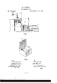
- Figure 1 represents a longitudinal vertical section of an apparatus embodying my invention.
- Fig. 2 is a perspective view of the box provided with the cover or lid, which is to be opened and locked by mechanism.
- the entire box is shown as divided into three compartments, designated, respectively, A B O.
- a B O Surmounting the compartment 0 is a pyramidically-shaped cover, W, having a narrow slot or opening at the top, adapted to receive a coin of any denomination from a cent to a twenty-five cent piece, or larger if required.
- W Surmounting the compartment 0 is a pyramidically-shaped cover, W, having a narrow slot or opening at the top, adapted to receive a coin of any denomination from a cent to a twenty-five cent piece, or larger if required.
- U From one side of the slot extends downward an inclined plate, U, which guides the coin in its descent to a tilting plate, T, as shown in Fig. 1.
- the plate T is of a sufficient length to insure the coin falling upon it from the inclined plate U.
- the plate T is hung to a rod, V, projecting from the inner side of the compartment 0, so as to allow the said plate to tilt freely, the portion that receives the coin being wider than that at the other side of the support, and this latter portion is counterbalanced by a weight, 10, so as to cause the plate to assume a horizontal position when freed from an inclined position.
- the plate T is prevented from tilting too far by a stop, 12, and held in a horizontal position by another stop, 2;, each attached to the end partition of the compartment 0.
- a narrow plate or bar, t Extending upward from the plate T, at or near its point of support, is a narrow plate or bar, t, which, when the plate T isin a horizontal position, sustains the end of a curved rod, R, which latter extends downward into the compartment A, and is rigidly attached at its lower end to a long bar or arm, H, extending toward the farther end of the compartment A, and pivoted at h to a small standard on the bottom of said compartment, so as to allow of a limited movement vertically of the longer end of arm H.
- the rod 1 extends upward through the front partition of the compartment or box B, and when the cover E is open the said rod projects slightly above the edge of the said partition, as shown in Fig. 2.
- a flat metal spring, 0, sunk in a recess at the front end of the lid, and provided with a projection or bolt that extends through the lid, and terminates in a knob, O, on the top.
- the lid is fastened by pressing the knob 0, when the cover is closed, the inner projection of the spring 0 being made to bear upon the top of the rod I, thus forcing the latter down and slightly turning the segment E.
- a notch or shoulder On the under side of the segment F is a notch or shoulder, which, when the segment is turned by the rod 1, engages with a tooth or projection, h, on the arm H, by means of which the segmexit is held in position until released by the dropping of the arm H.
- a projecting bar On the center of the segment F is a projecting bar, on which is hung a bar, G, extending downward to a point near the level of the arm H, (shown as broken off in the drawing, in order to expose the catch and its connection.)
- a rod, g To one'side of the bar G is attached to one'side of the bar G is attached a rod, g, which extends upward parallel with the rod I, and terminates in a hook or catch, 9, projecting from the front partition of the box B.
- the catch g" engages with ajaw or catch, P, on the under side of the front part of the cover, so as to hold the latter firmly in a closed position, and so that it cannot be opened without actuating the catch 9, through the mechanism put in operation by the dropping of the coin upon the tilting plate T.
- the bar G is drawn forward, to release the catch 9 in opening the lid E, by means of a spring-rod, R, attached to a projection on the segment F at one end, and to the side of the box or supporting-plate at the other end.
- the bar G is retracted, so as to throw the catch g forward into the catch P when the lid is to be fastened, by means of a spring, M, as shown, attached to a pin or projection, N.
- a short rod, 0, connected with a spring, S, in such a manner as to cause the cover to fly open when the catch is released.
- the side of thebox containing the operating mechanism is provided with a door, D, which is intended to be kept securely locked.
- the fastening of the lid E, which is effected by pressing down the knob 0, serves at the same time to set the mechanism for the reception of the coin to open the lid.
Landscapes
- Physics & Mathematics (AREA)
- General Physics & Mathematics (AREA)
- Toys (AREA)
- Coin-Freed Apparatuses For Hiring Articles (AREA)
- Control Of Vending Devices And Auxiliary Devices For Vending Devices (AREA)
Description
A. C. GOULD.
TOY MONEY-BOX.
No. 185,443. Patented Dec. 19, 1876.
WLtnesses: Y nventovi Jaw:
UNITED STATES Pmrn'r QFFICE- ARTHUR G. GOULD, OF BROOKLINE, MASSACHUSETTS.
IMPROVEMENT IN TOY MONEY-BOXES.
Specification forming part of Letters Patent No. 185,443, dated December 19, 1876 application filed October 2, 1876.
To all whom it may concern Be it known that I, ARTHUR O. GOULD, of Brookline, in the county of Norfolk and State of Massachusetts, have invented a Self-Opening-Box, of which the following is a specificatwo:
The object of my invention is to prevent access to a box to remove its contents without first dropping a coin into a separate receptacle, thesize or value of the coin depending upon the value of the article to be taken from the box.
The invention consists in a peculiar combination and arrangement of mechanism, whereby the box, when closed, is caused to be opened by simply dropping acoin into a narrow aperture provided for the purpose, so as to expose the contents of the box.
The invention also consists in a peculiar method of fastening the cover to the box when the same'is closed, which is effected by simply pressing a knob projecting from the cover near its front edge, which actuates the locking mechanism, so that the cover cannot again be opened except by dropping a coin again into the said narrow aperture, the mechanism being set by the act of locking the lid.
Referring to the drawings, Figure 1 represents a longitudinal vertical section of an apparatus embodying my invention. Fig. 2 is a perspective view of the box provided with the cover or lid, which is to be opened and locked by mechanism.
The entire box is shown as divided into three compartments, designated, respectively, A B O. Surmounting the compartment 0 is a pyramidically-shaped cover, W, having a narrow slot or opening at the top, adapted to receive a coin of any denomination from a cent to a twenty-five cent piece, or larger if required. From one side of the slot extends downward an inclined plate, U, which guides the coin in its descent to a tilting plate, T, as shown in Fig. 1. The plate T is of a sufficient length to insure the coin falling upon it from the inclined plate U. The plate T is hung to a rod, V, projecting from the inner side of the compartment 0, so as to allow the said plate to tilt freely, the portion that receives the coin being wider than that at the other side of the support, and this latter portion is counterbalanced by a weight, 10, so as to cause the plate to assume a horizontal position when freed from an inclined position. The plate T is prevented from tilting too far by a stop, 12, and held in a horizontal position by another stop, 2;, each attached to the end partition of the compartment 0. Extending upward from the plate T, at or near its point of support, is a narrow plate or bar, t, which, when the plate T isin a horizontal position, sustains the end of a curved rod, R, which latter extends downward into the compartment A, and is rigidly attached at its lower end to a long bar or arm, H, extending toward the farther end of the compartment A, and pivoted at h to a small standard on the bottom of said compartment, so as to allow of a limited movement vertically of the longer end of arm H. When the plate T is tilted by the coin falling upon it the bar or support 75 is drawn forward, as shown in dotted lines, allowing the end of the curved rod R to fall, and with it the arm H, thus releasing the tooth or projection h from the notch in the segment F. The arm H, with its attached rod R, is retracted by means of a spring, 00, as shown. To the inner side of the compartment A, or to a supporting-plate in the same, is pivoted or hung a segmental plate or disk, F, having on its inner or rear side a projection, '5, upon which latter rests the lower end of a rod, 1. The rod 1 extends upward through the front partition of the compartment or box B, and when the cover E is open the said rod projects slightly above the edge of the said partition, as shown in Fig. 2. To the under side of the lid E is attached a flat metal spring, 0, sunk in a recess at the front end of the lid, and provided with a projection or bolt that extends through the lid, and terminates in a knob, O, on the top. The lid is fastened by pressing the knob 0, when the cover is closed, the inner projection of the spring 0 being made to bear upon the top of the rod I, thus forcing the latter down and slightly turning the segment E. On the under side of the segment F is a notch or shoulder, which, when the segment is turned by the rod 1, engages with a tooth or projection, h, on the arm H, by means of which the segmexit is held in position until released by the dropping of the arm H. Above the center of the segment F is a projecting bar, on which is hung a bar, G, extending downward to a point near the level of the arm H, (shown as broken off in the drawing, in order to expose the catch and its connection.) To one'side of the bar G is attached a rod, g, which extends upward parallel with the rod I, and terminates in a hook or catch, 9, projecting from the front partition of the box B. The catch g" engages with ajaw or catch, P, on the under side of the front part of the cover, so as to hold the latter firmly in a closed position, and so that it cannot be opened without actuating the catch 9, through the mechanism put in operation by the dropping of the coin upon the tilting plate T. The bar G is drawn forward, to release the catch 9 in opening the lid E, by means of a spring-rod, R, attached to a projection on the segment F at one end, and to the side of the box or supporting-plate at the other end. The bar G is retracted, so as to throw the catch g forward into the catch P when the lid is to be fastened, by means of a spring, M, as shown, attached to a pin or projection, N. At the rear of the lid E is a short rod, 0, connected with a spring, S, in such a manner as to cause the cover to fly open when the catch is released. The side of thebox containing the operating mechanism is provided with a door, D, which is intended to be kept securely locked. The fastening of the lid E, which is effected by pressing down the knob 0, serves at the same time to set the mechanism for the reception of the coin to open the lid.
In operation, the mechanism being properly set, a coin is dropped in the proper opening, and falls upon plate T, causing it to' tilt, thus releasing the end of the curved rod It, and allowing thearm H to drop, and releasing the tooth h from the notch or shoulder in the bottom of segment F. The spring-K then draws the bar G forward, which causes the catch g to free itself from the catch P on the lid, which latter, being then free, is caused to fly open by the force of the spring S acting on the rod at the rear of lid E. In closing the lid the knob O is pressed down, causing the rod I to turn the disk F sufficiently to allow the tooth h to catch into the notch onthe disk. The spring M at the same time retracts the bar G, so as to cause the catch g toengage with the'catch P and lock the lid. The
spring at raises the end of arm H, and with it the rod R. The weight W restores the plate T to a horizontal position, bringing the sup port t under the end of rod It, and holding it in position until the plate Tisagain tilted by the coin dropping upon it.
What I claim as my invention is- 1. The combination of the tilting plate T, provided with a bar, t, for supporting the end. of the rod R, the arm H, provided with the projection h, and the notched segment I whereby the automatic opening of thelid E is effected upon the dropping of a coin on the tilting plate T, substantially as set forth.
2. The combination of the segment F, in connection with the springs K M, the bar G, and catch-rod g g, and the rod I, operated by the bolt 0, whereby the resetting of the mechanism for opening the lid is effected by the act of fastening the lid, substantially as described.
In testimony whereof I have signed my name to this specification in the presence of two subscribing witnesses.
ARTHUR (J. GOULD.
Witnesses:
J. H. ADAMS, E. A. STOCK.
Publications (1)
| Publication Number | Publication Date |
|---|---|
| US185443A true US185443A (en) | 1876-12-19 |
Family
ID=2254849
Family Applications (1)
| Application Number | Title | Priority Date | Filing Date |
|---|---|---|---|
| US185443D Expired - Lifetime US185443A (en) | Improvement in toy money-boxes |
Country Status (1)
| Country | Link |
|---|---|
| US (1) | US185443A (en) |
-
0
- US US185443D patent/US185443A/en not_active Expired - Lifetime
Similar Documents
| Publication | Publication Date | Title |
|---|---|---|
| US185443A (en) | Improvement in toy money-boxes | |
| US744673A (en) | Coin-controlled vending-machine for newspapers, magazines, &c. | |
| US555948A (en) | Mail-box | |
| US3941227A (en) | Coin box mechanism | |
| US397297A (en) | leavitt | |
| US226514A (en) | Coin holding and delivering device | |
| US1538591A (en) | Mail receptacle | |
| US713779A (en) | Coin-controlled apparatus. | |
| US751276A (en) | Vending-machine | |
| US1005382A (en) | Coin vending-machine. | |
| US914344A (en) | Slot-machine. | |
| US1220440A (en) | Automatic vending-machine. | |
| US1163080A (en) | Vending-machine. | |
| US436074A (en) | Vending-machine | |
| US633308A (en) | Coin-actuated book-receptacle. | |
| US1091824A (en) | Vending-machine. | |
| US777404A (en) | Vending-machine. | |
| US372175A (en) | s schiess | |
| US488610A (en) | Machine | |
| US935824A (en) | Coin-controlled vending-machine. | |
| US1944229A (en) | Vending machine | |
| US1218728A (en) | Coin-vending machine, (key.) | |
| US529222A (en) | Vending-machine | |
| US822598A (en) | Clock. | |
| US503139A (en) | Coin-controlled vending apparatus |