US1854424A - Jar capping mechanism - Google Patents
Jar capping mechanism Download PDFInfo
- Publication number
- US1854424A US1854424A US172385A US17238527A US1854424A US 1854424 A US1854424 A US 1854424A US 172385 A US172385 A US 172385A US 17238527 A US17238527 A US 17238527A US 1854424 A US1854424 A US 1854424A
- Authority
- US
- United States
- Prior art keywords
- levers
- jaws
- jar
- cap
- vacuum
- Prior art date
- Legal status (The legal status is an assumption and is not a legal conclusion. Google has not performed a legal analysis and makes no representation as to the accuracy of the status listed.)
- Expired - Lifetime
Links
Images
Classifications
-
- B—PERFORMING OPERATIONS; TRANSPORTING
- B67—OPENING, CLOSING OR CLEANING BOTTLES, JARS OR SIMILAR CONTAINERS; LIQUID HANDLING
- B67B—APPLYING CLOSURE MEMBERS TO BOTTLES JARS, OR SIMILAR CONTAINERS; OPENING CLOSED CONTAINERS
- B67B3/00—Closing bottles, jars or similar containers by applying caps
- B67B3/02—Closing bottles, jars or similar containers by applying caps by applying flanged caps, e.g. crown caps, and securing by deformation of flanges
- B67B3/10—Capping heads for securing caps
- B67B3/14—Capping heads for securing caps characterised by having movable elements, e.g. hinged fingers, for applying radial pressure to the flange of the cap
Definitions
- the invention relates to a jar capping mechanlsm, and has especial reference to a means for fastening a sheet metal cap upon producing a vacuum about the jar during the capping operation.
- The, primary object of my invention is to produce a jar capping means operable to vcrimp the skirt of a sealing cap beneath the locking shoulder of a jar, by the use of posi-y tive radially applied and nonrotating pressure means, whereby to perform the capping oplelration effectually',' rapidly and economi- ,ca y. 4
- Another object is to provide a cap securing means employing radial nonrotatable pressure devices which are positivelyactuated but capable of conforming to irregularities in the jar so as to avoid injury thereto or to the operating mechanism.
- Still another object of the invention is to provide a cap securing device which is especially adapted for use in connection with capshaving a plurality of fastening lugs formed in the skirt thereof at substantially equidistantly spaced intervals.
- a further object is to produce a capping device of the character referred to, combined with means for producing a vacuum about Athe jar whereby the cap vmay be applied and 'secured to the jar under a vacuum.
- a general object is to provide a jar capping mechanism which is exceedingly simple in construction and yet ⁇ eiectual in operation.
- Fig. 2 is a fragmentary vertical sectional view through the device, on an enlarged scale and showing the parts in the position occuufile at the end ofthe capping operation.
- Fig. 3 is a similar view ⁇ showng the relation of the parts vat another stage in the capping operation.
- Fig. 4 is a transgverse sectional view taken 60 approximately in the plane of line 4 4 of Fig. 2.
- Fig.,5 is an elevational view of the upper end of a jar having appliedv thereto a cap with spaced fastening lugs formed in the skirt' 66 thereof.
- v f is an elevational view of the upper end of a jar having appliedv thereto a cap with spaced fastening lugs formed in the skirt' 66 thereof.
- the embodiment selected for pur oses of illustration, 7 designates a vacuum c amber carried by a suitable support such as a table 8 andv having a hood 9 equipped with a suitable sealing gasket 10 adapted to seat upon the upper edge of the chamber 7
- the hood 9 has a central opening 11 in its upper end through which is entered a tubular reciprocable'member 12.
- LAs herein shown theJ hood is formed with an upwardly extending screw-threadednipple 13 adapted to receive a gland nut 14 operable to compress packing material 15 around the plunger, thus forming a stuing box permitting relative ⁇ axial movement of the member 12 with respect to the hood 9 While maintaining a frictional engagement between the parts.
- Ad-y iustably secured on the, member 12 is a col-y lar 16 between which and the nut 14 is inter- 85 posed a helically ,coiled spring 17.
- Downward pressure applied'to the member 12, as through. the medium of a lever 18, is thus yieldably transmitted by -the spring 17 to the 90 hood 9 so as to hold the latter with its seal- 4ing gasket 10 seated on-the upperl edge of the vacuum chamber 7.
- the lever 18 may, as shown in Fig. 1, be mounted in any suitable way as, for example, upon a bracket 19- supported by a standard 20, the lever having a pin and slot connection 21 with the tubular member 12.
- the standard 20 may be, if desired, in the form of .a column about which the 8 may rotate for the purpose of carryin the vacuum chamber 7 laterally into an out of relation to the hood 9.
- tubular stem 22 Slidable axially within the tubular member l2 is a tubular stem 22 which is made of a length substantially greater than the member 12 so as to project from opposite ends thereof.
- the lower end of the lstem 22 carries a cap-retaining head 23 in the form of a disk centrally apertured and screw-threaded upon the lower end of the stem, saidv disk having a peripheral flange 24 so that thel head is slightly cupped to receive the cap a.
- Means is provided for operating the tubular stem against the action of the spring, which means may comprise a hand lever 28 pivoted on a bracket 29 on the standard 20 and having a pin and slot connection 30 with the stem 22.
- the upper end of the stem 22 may be connected as by means of a flexible hose 31 with a suitable vacuum producing apparatus, the hose being herein shown as connected to a pipe 32 leading to such an apparatus, and having therein a three-way valve 33 adapted to be operated manually by'means of a hand lever 34.
- the valve is adapted to establish connection either with the vacuum producing apparatus or with the atmosphere, in a well knownmanner.
- the cap a has a peripheral skirt shaped to form a plurality of fastening lugs a at substantially equidistantly spaced intervals, which lugs are adapted to be bent or crimped beneath the locking shoulder b of a jab b of glass or other suitable material.
- the bending or ⁇ crimping of the lugs a into engagement with the locking shoulder b of' the jar is herein accomplished by means of four jaws 35, one for each of the lugs a',
- the jaws 35 are each carried at the lower end of a lever 36, the jaws being herein shown arcuate in form and substantially longer than the Width of the levers 36 as shown in Fig. 4.
- the levers are pivoted at 37 in a supporting member or spider 38 slidable o'n the tubular stem 22, the arms 39 of the spider being slotted as at 40 to receive the levers.
- the spider is supported by a stiff helically coiled spring 41 with the upper ends of the levers disposed in the path of a downwardly and inwardly tapering cam surface 42 on the lunger l2, the upper ends of the levers being correspondingly beveled as at 43.
- the upper ends of the levers 36 are adapted to engage with a shoulder 44 on the member 12 to limit outward and upward movement of the upper ends of the levers.
- a leaf spring ⁇ 45 may be provided for each lever, such springs acting between the levers and the adjacent wall of the hood 9 to force the jaws 35 outwardly when pressure upon the lever 18 ceases.
- the jar is placed within the vacuum chamber 7 with a cap thereon as shown in Fig- 3.
- the uppermost lever 28 is first operated and acting through the spring 27 moves the plunger 12 downwardly, the hood 9 moving with the plunger until the gasket 10 is seated upon the upper end of the vacuum chamber 7.
- the valve 33 is now operated to establish communica'- tion between the closed vacuum sealing chamber and the vacuum producing means, and air within the chamber and within the jar is exhausted.
- the lever 28 is now operated still further to move the tubular stem 22 downwardly, carrying the cap retaining head 23 into engagement with the cap, the spring 27* yielding for this purpose. It will be observed (Fig.
- the jaws 35 are positioned adjacent the skirt of the cap a, a short distance above the locking shoulder.
- the cam surface 42 engages with the beveled upper ends of the levers 36, and operates to force the lower ends of the levers inwardly while at the same time tending to move the levers downwardly.
- the jaws 35 slidahly engage with the outer sides of the lugs n. of the cap and due to their combined inward and downward movement, force the lower ends of 'the lugs pro jecting below the locking shoulder '13', posil-of the jar being capped.
- valve 33 is operated to cut 0H communication between the vacuum producing apparatus and the vacuum chamber, and the levers 18 and 28 operated to restore the parts to their initial positions. In this latter operation frictional engagement between the hood 9 and the plunger 12 edected by the stuffing box 13,
- a jar capping mechanism comprising,
- a cap retaining head in combination, a cap retaining head, -a reciprocable stem carrying said head, a member encircling said stem, a plurality of levers pivoted to said member, ⁇ crimping jaws actuated by said levers, a reciprocatory positively actuated cam member for actuating said levers, and a spring interposed between said first mentioned member and said head adapted to-yield to permit downward movement of the aws during the crimping operation.
- a jar capping mechanism comprising, in combination, a pairofprelatively movable coaxial members, the inner one of said members being tubular and adapted for connection with a vacuum producing apparatus, a
- ' cap retaining head carried bythe inner mem# ber, a plurality of jaws mounted for radial movement, avacuum sealing chamber comprising a hood movable with the outer member, and means also actuated in the movement of the outer member to operate said aws.
- a jar capping mechanism comprising, in combination, a pair of-relatively movable coaxial members, the inner one of said members being tubular and adapted for connection with a vacuum producing apparatus, a. cap retaining head carried by the inner member, a plurality of jaws mounted for radial movement, a vacuum sealingchamber comprising a hood movable with the outer member, means also actuated in the movement of the outer member to operate said jaws, the last mentionedl means comprising a plurality of levers, and ca'm meansoperated by said outer member and adapted to engage said levers, a support for said levers, and a spring acting between said support and said head adapted to permit said jaws toemove axially in their movement by said outer member.
- a jar capping mechanism comprising, in combination, a pair of relatively movable axial members the inner one of which is tubularand is adapted for connection with a
- cap-applying means comprising a'capping head carried b the inner member, a plurality of levers each aving a jaw at its lower end and a support encircling the inner one of said members and providing a fulcrum for each of said levers, the outer one of said members being adapted to engage with said levers to move the jaws radially, and a vacuum-sealing chamber comprising a hood movable by the outer member, said hood being adapted Y .to enclose said cap-applying-means.
- a jar capping mechanlsm comprising, in combination, a pair of relatively movable axial members thel inner one of which is tubular and is adapted for connection with a vacuum producing apparatus, and cap-applying means comprising a capping head ⁇ car ried by the inner member, a hood for enclosing the can-applying means lcarried by the outer member, a plurality of llevers each having 'a jaw at its lower end and a support providing a fulcrum for each of said levers,
- the outer one of said ⁇ members being adapted Y to engage with said levers tomove the jawsl radially, and spring means acting between said hood and said levers tending to move said jaws outwardly.
- a jar capping mechanism comprising, in combination, a tubular member mounted for up and.l down movements and adapted for connectionwith a vacuum. producingapparatus, a cap-applying head carried by said member, a plurality of crimping aws, means for pivotally supporting said jaws for radial movement, a vacuum sealing-chamber com- (prising separable sections, and means pass ing through one of said sections adapted to operate said jaws.
- a jar capping mechanism comprising, in combination, a tubular member mounted for up and down movements and adapted for connection wit a vacuum producing apparatus, a cap-app ying head carried by said member, a plurality of crimping jaws, means for pivotally supporting said aws for radial movement, a vacuum sealing-chamber, and means passing through said chamber adapted to operate said jaws.
- A. jar capping mechanism comprising,
- a reciprocable member carrying a cap retaining head at one end
- a second reciprocable member movable relative to said rst member
- a plurality of levers mslidably and pivotally mounted relative to said first member, crimping jaws actuated by said levers, yielding means to resist translation of said levers in one direction, and cam means on said second member acting upon saidlevers to vinitially translate said levers in opposition to said yielding means and finally to rotate said levers to eil'ect a crimping action on a cap.
- a jar capping mechanism comprising, in combination, a pair of relatively movable coaxial members, a spider slidably fitted on the inner oneof said members, a plurality of levers pivotally connected to said spider, sprin g means yieldably restraining movement of said spider in one direction, a cam surface on the outer one of said members contact-ing with said levers to positively urge said spider in an opposed direction.
- a jar capping mechanism comprising, in combinatiom'a pair of relatively movable coaxial members the inner one of which is hollow and isy adapted for connection with, a vacuum producing apparatus, and a capapplying means comprising a capping head carried by the inner member, a plurality of lever actuated jaws carried by and encircling said member, and a vacuum sealing chamber having separable sections, one of said sections being yieldably mounted on said outer member to permit movement of said member relative to said section for the actuation of said jaws.
Landscapes
- Engineering & Computer Science (AREA)
- Mechanical Engineering (AREA)
- Filling Of Jars Or Cans And Processes For Cleaning And Sealing Jars (AREA)
Description
Patented Apr. 19, 1932 ITED WILLIS J'. PELLE, OF CHICAGQ, ILLZJINOIS JAR CAPPIG vMIEGHANISM Application mea March a, 1927'. serial No. 172,385
The invention relates to a jar capping mechanlsm, and has especial reference to a means for fastening a sheet metal cap upon producing a vacuum about the jar during the capping operation.
The, primary object of my invention is to produce a jar capping means operable to vcrimp the skirt of a sealing cap beneath the locking shoulder of a jar, by the use of posi-y tive radially applied and nonrotating pressure means, whereby to perform the capping oplelration effectually',' rapidly and economi- ,ca y. 4
Another object is to provide a cap securing means employing radial nonrotatable pressure devices which are positivelyactuated but capable of conforming to irregularities in the jar so as to avoid injury thereto or to the operating mechanism.
Still another object of the invention Ais to provide a cap securing device which is especially adapted for use in connection with capshaving a plurality of fastening lugs formed in the skirt thereof at substantially equidistantly spaced intervals.
A further object is to produce a capping device of the character referred to, combined with means for producing a vacuum about Athe jar whereby the cap vmay be applied and 'secured to the jar under a vacuum.
A general object is to provide a jar capping mechanism which is exceedingly simple in construction and yet`eiectual in operation.
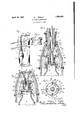
The objects of the invention thus generally stated, together with other and ancillary advantages, are attained by the construction and arrangement illustrated in the accomvpanyingdrawings forming part hereof. It -should be understood however that it is contemplated that various changes in the -con- 'r struction and arrangement herein set forth may be made by those skilled in the art without departing from the spirit and scope of the invention as expressed in the appended claims. 50 Figure 1 of the drawings is a fragmentary side elevational view of a vacuum capping mechanism embodying my invention. J
Fig. 2 is a fragmentary vertical sectional view through the device, on an enlarged scale and showing the parts in the position occuu pied at the end ofthe capping operation.
Fig. 3 is a similar view\showng the relation of the parts vat another stage in the capping operation.
Fig. 4 is a transgverse sectional view taken 60 approximately in the plane of line 4 4 of Fig. 2.
Fig.,5 is an elevational view of the upper end of a jar having appliedv thereto a cap with spaced fastening lugs formed in the skirt' 66 thereof. v f
1n the embodiment selected for pur oses of illustration, 7 designates a vacuum c amber carried by a suitable support such as a table 8 andv having a hood 9 equipped with a suitable sealing gasket 10 adapted to seat upon the upper edge of the chamber 7 The hood 9 has a central opening 11 in its upper end through which is entered a tubular reciprocable'member 12. LAs herein shown theJ hood is formed with an upwardly extending screw-threadednipple 13 adapted to receive a gland nut 14 operable to compress packing material 15 around the plunger, thus forming a stuing box permitting relative `axial movement of the member 12 with respect to the hood 9 While maintaining a frictional engagement between the parts. Ad-y iustably secured on the, member 12 is a col-y lar 16 between which and the nut 14 is inter- 85 posed a helically ,coiled spring 17. Downward pressure applied'to the member 12, as through. the medium of a lever 18, is thus yieldably transmitted by -the spring 17 to the 90 hood 9 so as to hold the latter with its seal- 4ing gasket 10 seated on-the upperl edge of the vacuum chamber 7.- The lever 18 may, as shown in Fig. 1, be mounted in any suitable way as, for example, upon a bracket 19- supported by a standard 20, the lever having a pin and slot connection 21 with the tubular member 12. The standard 20 may be, if desired, in the form of .a column about which the 8 may rotate for the purpose of carryin the vacuum chamber 7 laterally into an out of relation to the hood 9.
Slidable axially within the tubular member l2 is a tubular stem 22 which is made of a length substantially greater than the member 12 so as to project from opposite ends thereof. The lower end of the lstem 22 carries a cap-retaining head 23 in the form of a disk centrally apertured and screw-threaded upon the lower end of the stem, saidv disk having a peripheral flange 24 so that thel head is slightly cupped to receive the cap a. A stuiiing box 25, which may be similar in all substantial respects to the stufling box 14, is vprovided between the upper end of the tubular member l2 and the stem 22, and between the nut of this stufling box and a collar 26 on the tubular stem is interposed a coiled spring 27 tending to lift the capping head 23 relative to the hood 9. Means is provided for operating the tubular stem against the action of the spring, which means may comprise a hand lever 28 pivoted on a bracket 29 on the standard 20 and having a pin and slot connection 30 with the stem 22.
The upper end of the stem 22 may be connected as by means of a flexible hose 31 with a suitable vacuum producing apparatus, the hose being herein shown as connected to a pipe 32 leading to such an apparatus, and having therein a three-way valve 33 adapted to be operated manually by'means of a hand lever 34. The valve is adapted to establish connection either with the vacuum producing apparatus or with the atmosphere, in a well knownmanner.
As herein shown the cap a has a peripheral skirt shaped to form a plurality of fastening lugs a at substantially equidistantly spaced intervals, which lugs are adapted to be bent or crimped beneath the locking shoulder b of a jab b of glass or other suitable material. The bending or `crimping of the lugs a into engagement with the locking shoulder b of' the jar is herein accomplished by means of four jaws 35, one for each of the lugs a',
` these jaws being, according tothe present inj vention, movable through the operation of the lever 18 acting through the tubular member 12 which constitutes a plunger for this purpose.
The jaws 35 are each carried at the lower end of a lever 36, the jaws being herein shown arcuate in form and substantially longer than the Width of the levers 36 as shown in Fig. 4. The levers are pivoted at 37 in a supporting member or spider 38 slidable o'n the tubular stem 22, the arms 39 of the spider being slotted as at 40 to receive the levers. The spider is supported by a stiff helically coiled spring 41 with the upper ends of the levers disposed in the path of a downwardly and inwardly tapering cam surface 42 on the lunger l2, the upper ends of the levers being correspondingly beveled as at 43.
It will be seen that in the downward movement of the member 12, through the operation of the lever 18, the upper ends of the levers 36 are forced outwardly so as to carry the jaws 35 at the lower ends of the levers inwardly. In this operation a downward thrust is imparted to the levers so that the jaws are given a combined downward and inward movement, exerting a radial pressure upon the lugs a of the cap. ,The spring 41 yields, in this operation, to permit the downward movement of the jaws as they move inwardly, the supporting spider 38, by reason of its fit on theI stem 22, being capable of adjusting itself as may be required. This is especially desirable for the reason that in practice jars are found to be lacking in uni formity and to possess irregularities as regards the dimensions of the upper end portions of the ars.
Preferably the upper ends of the levers 36 are adapted to engage with a shoulder 44 on the member 12 to limit outward and upward movement of the upper ends of the levers. And to insure that the levers will disengage from the locking shoulder of the jar after the capping operation, a leaf spring` 45 may be provided for each lever, such springs acting between the levers and the adjacent wall of the hood 9 to force the jaws 35 outwardly when pressure upon the lever 18 ceases.
In the operation of the capping mechanism as herein set forth, the jar is placed within the vacuum chamber 7 with a cap thereon as shown in Fig- 3. The uppermost lever 28 is first operated and acting through the spring 27 moves the plunger 12 downwardly, the hood 9 moving with the plunger until the gasket 10 is seated upon the upper end of the vacuum chamber 7. The valve 33 is now operated to establish communica'- tion between the closed vacuum sealing chamber and the vacuum producing means, and air within the chamber and within the jar is exhausted. The lever 28 is now operated still further to move the tubular stem 22 downwardly, carrying the cap retaining head 23 into engagement with the cap, the spring 27* yielding for this purpose. It will be observed (Fig. 3) that in this relation of the parts, the jaws 35 are positioned adjacent the skirt of the cap a, a short distance above the locking shoulder. When, therefore, downward pressure is now applied to the 1e ver 18, the spring 17 yielding, the cam surface 42 engages with the beveled upper ends of the levers 36, and operates to force the lower ends of the levers inwardly while at the same time tending to move the levers downwardly. In this operation of the levers, the jaws 35 slidahly engage with the outer sides of the lugs n. of the cap and due to their combined inward and downward movement, force the lower ends of 'the lugs pro jecting below the locking shoulder '13', posil-of the jar being capped. Finally the valve 33 is operated to cut 0H communication between the vacuum producing apparatus and the vacuum chamber, and the levers 18 and 28 operated to restore the parts to their initial positions. In this latter operation frictional engagement between the hood 9 and the plunger 12 edected by the stuffing box 13,
14 is suflicient to lift the hood 9 from oil' the chamber 7 herein described my invention as applied to the securing of a particular form of cap, it might readily be alteredl by increasing the number of jaws to operate upon caps of ordinary construction having the skirt of the cap of uniform depth throughout the periphery of the cap.
I claim as my invention: 1. A jar capping mechamsm comprislng,
' in combination, a reciprocating cap retaining ment of the jaws while they move inwardly. l
head, a plurality of jaws, a plurality of levers carrying, said jaws, spring means normally restraining rotation of said levers, a support for said levers movable with said head, a spring acting between said support and said head, and positively actuated means Jfor swinging the levers to cause the jaws to move radially relative to a jar, said spring being adapted to yield to permit downward move- 2. A jar capping mechanism comprising,
in combination, a cap retaining head, -a reciprocable stem carrying said head, a member encircling said stem, a plurality of levers pivoted to said member,`crimping jaws actuated by said levers, a reciprocatory positively actuated cam member for actuating said levers, and a spring interposed between said first mentioned member and said head adapted to-yield to permit downward movement of the aws during the crimping operation.
3. A jar capping mechanism comprising, in combination, a pairofprelatively movable coaxial members, the inner one of said members being tubular and adapted for connection with a vacuum producing apparatus, a
' cap retaining head carried bythe inner mem# ber, a plurality of jaws mounted for radial movement, avacuum sealing chamber comprising a hood movable with the outer member, and means also actuated in the movement of the outer member to operate said aws.
4. A jar capping mechanism comprising, in combination, a pair of-relatively movable coaxial members, the inner one of said members being tubular and adapted for connection with a vacuum producing apparatus, a. cap retaining head carried by the inner member, a plurality of jaws mounted for radial movement, a vacuum sealingchamber comprising a hood movable with the outer member, means also actuated in the movement of the outer member to operate said jaws, the last mentionedl means comprising a plurality of levers, and ca'm meansoperated by said outer member and adapted to engage said levers, a support for said levers, and a spring acting between said support and said head adapted to permit said jaws toemove axially in their movement by said outer member.
5. A jar capping mechanism comprising, in combination, a pair of relatively movable axial members the inner one of which is tubularand is adapted for connection with a It will be understood that while I have vacuum producing apparatus, and cap-applying means comprising a'capping head carried b the inner member, a plurality of levers each aving a jaw at its lower end and a support encircling the inner one of said members and providing a fulcrum for each of said levers, the outer one of said members being adapted to engage with said levers to move the jaws radially, and a vacuum-sealing chamber comprising a hood movable by the outer member, said hood being adapted Y .to enclose said cap-applying-means.
6. A jar capping mechanlsm comprising, in combination, a pair of relatively movable axial members thel inner one of which is tubular and is adapted for connection with a vacuum producing apparatus, and cap-applying means comprising a capping head `car ried by the inner member, a hood for enclosing the can-applying means lcarried by the outer member, a plurality of llevers each having 'a jaw at its lower end and a support providing a fulcrum for each of said levers,
the outer one of said `members being adapted Y to engage with said levers tomove the jawsl radially, and spring means acting between said hood and said levers tending to move said jaws outwardly.
7 A jar capping mechanism comprising, in combination, a tubular member mounted for up and.l down movements and adapted for connectionwith a vacuum. producingapparatus, a cap-applying head carried by said member, a plurality of crimping aws, means for pivotally supporting said jaws for radial movement, a vacuum sealing-chamber com- (prising separable sections, and means pass ing through one of said sections adapted to operate said jaws. i
8. A jar capping mechanism comprising, in combination, a tubular member mounted for up and down movements and adapted for connection wit a vacuum producing apparatus, a cap-app ying head carried by said member, a plurality of crimping jaws, means for pivotally supporting said aws for radial movement, a vacuum sealing-chamber, and means passing through said chamber adapted to operate said jaws.
' 5 9. A. jar capping mechanism comprising,
in combination, a reciprocable member carrying a cap retaining head at one end, a second reciprocable member movable relative to said rst member, a plurality of levers mslidably and pivotally mounted relative to said first member, crimping jaws actuated by said levers, yielding means to resist translation of said levers in one direction, and cam means on said second member acting upon saidlevers to vinitially translate said levers in opposition to said yielding means and finally to rotate said levers to eil'ect a crimping action on a cap.
10. A jar capping mechanism comprising, in combination, a pair of relatively movable coaxial members, a spider slidably fitted on the inner oneof said members, a plurality of levers pivotally connected to said spider, sprin g means yieldably restraining movement of said spider in one direction, a cam surface on the outer one of said members contact-ing with said levers to positively urge said spider in an opposed direction.
11. A jar capping mechanism, comprising, in combinatiom'a pair of relatively movable coaxial members the inner one of which is hollow and isy adapted for connection with, a vacuum producing apparatus, and a capapplying means comprising a capping head carried by the inner member, a plurality of lever actuated jaws carried by and encircling said member, and a vacuum sealing chamber having separable sections, one of said sections being yieldably mounted on said outer member to permit movement of said member relative to said section for the actuation of said jaws.
In testimony whereof, I have hereunto aiiiXed my signature. WILLIS J. PEELLE.
Priority Applications (1)
| Application Number | Priority Date | Filing Date | Title |
|---|---|---|---|
| US172385A US1854424A (en) | 1927-03-03 | 1927-03-03 | Jar capping mechanism |
Applications Claiming Priority (1)
| Application Number | Priority Date | Filing Date | Title |
|---|---|---|---|
| US172385A US1854424A (en) | 1927-03-03 | 1927-03-03 | Jar capping mechanism |
Publications (1)
| Publication Number | Publication Date |
|---|---|
| US1854424A true US1854424A (en) | 1932-04-19 |
Family
ID=22627493
Family Applications (1)
| Application Number | Title | Priority Date | Filing Date |
|---|---|---|---|
| US172385A Expired - Lifetime US1854424A (en) | 1927-03-03 | 1927-03-03 | Jar capping mechanism |
Country Status (1)
| Country | Link |
|---|---|
| US (1) | US1854424A (en) |
Cited By (5)
| Publication number | Priority date | Publication date | Assignee | Title |
|---|---|---|---|---|
| US2697996A (en) * | 1949-11-04 | 1954-12-28 | Ebauches Sa | Closing tool |
| US2750094A (en) * | 1951-07-03 | 1956-06-12 | American Can Co | Container overcap and method of attaching same without adhesive |
| US2853037A (en) * | 1953-10-28 | 1958-09-23 | Gen Electric | Integral pin forming machine |
| US4447184A (en) * | 1981-10-13 | 1984-05-08 | Nyffeler, Corti Ag | Apparatus for sealing containers |
| US6070750A (en) * | 1986-12-01 | 2000-06-06 | Kubitz; Terry E. | Reinforced container and method for producing same |
-
1927
- 1927-03-03 US US172385A patent/US1854424A/en not_active Expired - Lifetime
Cited By (5)
| Publication number | Priority date | Publication date | Assignee | Title |
|---|---|---|---|---|
| US2697996A (en) * | 1949-11-04 | 1954-12-28 | Ebauches Sa | Closing tool |
| US2750094A (en) * | 1951-07-03 | 1956-06-12 | American Can Co | Container overcap and method of attaching same without adhesive |
| US2853037A (en) * | 1953-10-28 | 1958-09-23 | Gen Electric | Integral pin forming machine |
| US4447184A (en) * | 1981-10-13 | 1984-05-08 | Nyffeler, Corti Ag | Apparatus for sealing containers |
| US6070750A (en) * | 1986-12-01 | 2000-06-06 | Kubitz; Terry E. | Reinforced container and method for producing same |
Similar Documents
| Publication | Publication Date | Title |
|---|---|---|
| US1854424A (en) | Jar capping mechanism | |
| US1022591A (en) | Capping-machine. | |
| US2017766A (en) | Sealing machine and method | |
| US1371244A (en) | Filling-head | |
| US2297720A (en) | Foil applying apparatus for bottles | |
| US2320515A (en) | Capping device | |
| US1060201A (en) | Sealing-machine. | |
| US2149377A (en) | Apparatus for capping bottles | |
| US2842916A (en) | Device for vacuum sealing containers | |
| GB767029A (en) | Containers with detachable closures and capping mechanism for assembling the parts | |
| US1080277A (en) | Package-capping machine. | |
| US391760A (en) | noeton | |
| US2778179A (en) | Container cap-seal and sealing apparatus | |
| US1125041A (en) | Carton-capping machine. | |
| US880671A (en) | Bottle-capping machine. | |
| US979766A (en) | Bottle-capping machine. | |
| US917344A (en) | Bottle-capping machine. | |
| US3334467A (en) | Vacuum sealing machine | |
| US1670924A (en) | Capping machine | |
| US939141A (en) | Bottle-capping machine. | |
| US2134923A (en) | Tool for applying seal caps | |
| US983829A (en) | Mechanism for applying bottle-caps. | |
| US1305765A (en) | Albert r | |
| US2193113A (en) | Sealing machine | |
| US1348908A (en) | Bottle-capping apparatus |