US1854380A - Cigarette lighter and dispenser - Google Patents
Cigarette lighter and dispenser Download PDFInfo
- Publication number
- US1854380A US1854380A US42905A US4290525A US1854380A US 1854380 A US1854380 A US 1854380A US 42905 A US42905 A US 42905A US 4290525 A US4290525 A US 4290525A US 1854380 A US1854380 A US 1854380A
- Authority
- US
- United States
- Prior art keywords
- cigarette
- dispenser
- casing
- container
- ignition
- Prior art date
- Legal status (The legal status is an assumption and is not a legal conclusion. Google has not performed a legal analysis and makes no representation as to the accuracy of the status listed.)
- Expired - Lifetime
Links
Images
Classifications
-
- A—HUMAN NECESSITIES
- A24—TOBACCO; CIGARS; CIGARETTES; SIMULATED SMOKING DEVICES; SMOKERS' REQUISITES
- A24F—SMOKERS' REQUISITES; MATCH BOXES; SIMULATED SMOKING DEVICES
- A24F15/00—Receptacles or boxes specially adapted for cigars, cigarettes, simulated smoking devices or cigarettes therefor
- A24F15/02—Receptacles or boxes specially adapted for cigars, cigarettes, simulated smoking devices or cigarettes therefor for domestic use
- A24F15/08—Receptacles or boxes specially adapted for cigars, cigarettes, simulated smoking devices or cigarettes therefor for domestic use combined with other objects
- A24F15/10—Receptacles or boxes specially adapted for cigars, cigarettes, simulated smoking devices or cigarettes therefor for domestic use combined with other objects with lighters
Definitions
- This invention relates to improvements in electric cigarette lighting devices for automobiles, and particularly represents an 1mprovement over that type of device shown in my copending application for patent filed February 5th, 1923, Serial No. 16,906. This application also represents improvements over my Patent No. 1,520,367, dated December 23rd, 1924. v
- One of the objects of the present invention therefore is to construct the ignition unit 7 in such a way that a safety switch is incorporated therewith, which will close automatically only when one end of the cigarette is pressed against the ignition element.
- the cigarette when being ignited is therefore subjected to the heat of the element, only for a suflicent length of time necessary to properly ignite the same, and unnecessary use'of the current is avoided.
- Another object is to construct this unit in such a manner that the element may be easily replaced when necessary without undue work. Also the switch contacts are concealed instead of being out in the open as before,
- a further object is to provide means for dispensing a cigarette from the container to the supporting means which are arranged in line with the suction and ignition members, and arranged-so that the operation of the dispensing means will automatically cause the suction to function and the ignition element to be moved into frictional engagement with the cigarette.
- Manipulation of one member therefore not only causes the cigarette to be dispensed but lighting operations to take place as well.
- a further object of the invention is to produce a simple and inexpensive device and yet one which will be exceedingly effective for the purpose for which it is designed.
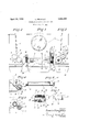
- Fig. 1 is a front view of the instrument.
- Figs. 2 and 3 are end elevations taken from the left and right hand ends respectively of the instrument.
- Fig. 4 is a fragmentary vertical section on the line 4-4 of Fig. 1.
- Fig. 5 is a similar view taken on the line 55 of Fig. 1.
- Fig. 6 is a plan view of the dispenslng member detached.
- Fig. 7 is an enlarged section of the ignition element unit taken on the line 77 of Fig. 3.
- the numeral 1 denotes the container adapted to receive a number of cigarettes in horizontal order, and having end walls 2 projecting outwardly from and extending a certain distance below said container.
- a dispensing element comprising a cylindrlcal member 3 cut away intermediate its ends to form a longitudinal slot 4. for the reception of a cigarette?
- This dispenser projects through the end walls 2 and has on its right hand end a radial operating handle 5.
- the opposite end of the dispenser hasaturnin fitina sleeve-6 mounted on the. ad'acent en wall 2.
- a pipe 8 adapted to be connected to a source of suction, is connected to the sleeve 6, while another passage member 9 c1rcumferentially spaced from the pipe 8, leads from the sleeve 6 to the bore of a suction cup 10 which is adapted to receive one end of a cigarette therein.
- This cup is mounted on the adjacent wall 2 in alinement with the cradles and facing the opposite wall 2.
- the portion of the dispensing member 3 which is mounted in the sleeve 6 is provided with a circumferential slot 11 to register with and extend between the pipes 8 and 9, so as to provide a suctional force in the cup. This slot is so positioned relative to the slot 4 that it will only thus register after the dispenser has been rotated a suflicient distance to invert the slot 4 from its normal position and discharge a ci arette ontothe cradles.
- an ignition element structure including a casing structure 12.
- This casing is mounted on a strip 13 which passes over theadj acent end of the dispenser 3, to a slidable connection with an anchor pin 14 beyond said dispenser and which is mounted on the wall 2.
- the strip 13 is normally held in spaced relation to said end wall by means of spring feet 15 provided therewith intermediate its ends, which extend to and bear against the wall 2, on the opposite sides of the member 3.
- a cam 16 is providedin connection with a collar 17 which is mounted on the member 3 outwardly of the strip 13, said collar being held in place by the handle 5 which is also disposed outwardly of the member 13.
- This cam is arranged so as to bear against one side edge of the strip 13 and depress the same toward the wall 2, only after the dispenser has been rotated a sufiicient distance to discharge a cigarette onto the cradles.
- the ignition element 18 (which as hereinafter set forth is mounted on the inner end of the casing 12) is then forced into engagement with the adjacent end of the cigarette, and at the same time the latter is moved along the cradles into engagement with the suction cup.
- the front wall 19 ofthe structure below the container is located a certain distance in front of the front wall of the container, and aced relation thereto as shown, so as to enab e a cigarette to be readily lifted by the fingers from the cradles.
- Anash receptacle 20 is preferably mounted in a removable manner on the bottom of the structure, so that any ashes falling from a cigarette during its ignition will be caught. Cigar and cigarette butts and ashes as formed on the same when being smoked may also be dropped into the receptacle through the space between the wall 19 and the container above.
- a disc '21 of insulation material Slidably mounted in the casing 12 is a disc '21 of insulation material, on the outer face of which the element 18 is mounted.
- This casing is adapted to roject through an orifice 22 provided in t e adjacent wall 2, so that the element may engage the cigarette.
- the disc is prevented from moving outwardly from the casing b' a flange 23 on the latter, at the end thereo nearest the wall 2.
- the ends of the element are connected to pins 24 and 25 mounted in the disc and projecting therethrough.
- a weak flatcompression spring 26 is connected, which constantly bears against a screw 27 centrally mounted in the cap 28 which is provided on the outer end of the casing, the screw being insulated from the cap and casing.
- the hot cutting of! the sucwire 29 projects through a suitable slot in the side of the cap and casing and is connected to the screw 27.
- the other pin 25 is normally spaced from a transverse partition 30 mounted in the easing inwardly of thewire 29.
- This partition 30 is of electrical conductivity, and is in di-' rect contact with the casing.
- This casing by means of the support 13 is connected to the metal of the container 1 which in turn being mounted on the car is grounded thereon.
- the container is preferably wider at the bottom than at the top, and has an inwardly projecting ledge in front just above the dispenser, as shown.
- the first feature of construction allows the cigarettes to drop freel r into the dispenser, while the latter prevents them from possibly jamming between the container and dispenser.
- the open-front container and cradle arrangement makes it easy to place a cigarette, on the cradles by hand, to enable the same to be ignited, should the container be empty.
- the ash receptacle will catch any burning substance, and prevent possible damage to the car.
- said igniter comprising a casing, an insulation block slidably mounted therein, an ignition element on the block, normally spaced cooperating contacts on the block and casing adapted to engage when the block moves inwardly of the casing, and means to advance the casing toward a supported cigarette.
- a movable dispensing member a support for a dispensed cigarette, an igniter at one end of the support to engage one end of a cigarette thereon, the movement of said dispensing member being rotary, a supporting strip for said igniter slidably mounted on the dispensing member, a cam on said member to engage and move the strip so that the igniter is moved toward the support with the turning of the member beyond a cigarette dispensing position, and spring means resisting such movement of the strip.
Landscapes
- Manufacturing Of Cigar And Cigarette Tobacco (AREA)
Description
April 19, 1932. PENGILLY 1,854,380
CIGARETTE LIGHTER AND DISPENSER Filed July 11, 1925 INVENTOR L ews'Peng 6603 BY (L Q many;
ATTORN EY Patented Apr. 19, 1932 UNITED STATES LEWIS PENGILIIY, SAN FRANCISCO, CALIFORNIA.
CIGARETTE LIGHTER AND DISPENSER a ummn fled m 11, 1925. min No. 42,005.
This invention relates to improvements in electric cigarette lighting devices for automobiles, and particularly represents an 1mprovement over that type of device shown in my copending application for patent filed February 5th, 1923, Serial No. 16,906. This application also represents improvements over my Patent No. 1,520,367, dated December 23rd, 1924. v
These previous devices included a contamer; means for supporting the cigarettes as dispensed from the container; a suction element at one end of the support; an ignition element in the other end; and means for both causing the opposite ends of the cigarette to be engaged with the suction and ignition elements, and at the same time closing the switch through the heater. This operation was entirely independent of the operation necessary to dispense the cigarettes from the container. The switch means were manually controlled, and functioned to cause the suctional force to be exerted in the suction member, and the ignition element to be heated, regardless of 2 any cigarette being on the supporting means.
One of the objects of the present invention therefore is to construct the ignition unit 7 in such a way that a safety switch is incorporated therewith, which will close automatically only when one end of the cigarette is pressed against the ignition element.
This not only insures that the element will be heated only when its use is actually desired, but as the cigarette burns away a 5 short distance and thus releases the pressure of the cigarette against the element, the safety switch to the latter will be automatically opened.
The cigarette when being ignited is therefore subjected to the heat of the element, only for a suflicent length of time necessary to properly ignite the same, and unnecessary use'of the current is avoided.
Another object is to construct this unit in such a manner that the element may be easily replaced when necessary without undue work. Also the switch contacts are concealed instead of being out in the open as before,
and the chances of the contacts becoming fouled are therefore lessened.
A further object is to provide means for dispensing a cigarette from the container to the supporting means which are arranged in line with the suction and ignition members, and arranged-so that the operation of the dispensing means will automatically cause the suction to function and the ignition element to be moved into frictional engagement with the cigarette.
Manipulation of one member therefore not only causes the cigarette to be dispensed but lighting operations to take place as well.
A further object of the invention is to produce a simple and inexpensive device and yet one which will be exceedingly effective for the purpose for which it is designed.
These objects I accomplish by means of such structure and relative arrangement of parts as will fully appear by a perusal of the following specification and claims.
In the drawings similar characters of reference indicate corresponding parts in the several views:
Fig. 1 is a front view of the instrument.
Figs. 2 and 3 are end elevations taken from the left and right hand ends respectively of the instrument.
Fig. 4 is a fragmentary vertical section on the line 4-4 of Fig. 1.
Fig. 5 is a similar view taken on the line 55 of Fig. 1.
Fig. 6 is a plan view of the dispenslng member detached.
Fig. 7 is an enlarged section of the ignition element unit taken on the line 77 of Fig. 3.
Referring now more particularly to the characters of reference on the drawings, the numeral 1 denotes the container adapted to receive a number of cigarettes in horizontal order, and having end walls 2 projecting outwardly from and extending a certain distance below said container.
Discharge from the bottom of the container is controlled b a dispensing element comprising a cylindrlcal member 3 cut away intermediate its ends to form a longitudinal slot 4. for the reception of a cigarette? This dispenser projects through the end walls 2 and has on its right hand end a radial operating handle 5. The opposite end of the dispenser hasaturnin fitina sleeve-6 mounted on the. ad'acent en wall 2.
e dispenser discharges onto cigarettesupporting cradles 7 disposed below the dispenser and a certain distance in front of the same. A pipe 8, adapted to be connected to a source of suction, is connected to the sleeve 6, while another passage member 9 c1rcumferentially spaced from the pipe 8, leads from the sleeve 6 to the bore of a suction cup 10 which is adapted to receive one end of a cigarette therein. This cup is mounted on the adjacent wall 2 in alinement with the cradles and facing the opposite wall 2. The portion of the dispensing member 3 which is mounted in the sleeve 6 is provided with a circumferential slot 11 to register with and extend between the pipes 8 and 9, so as to provide a suctional force in the cup. This slot is so positioned relative to the slot 4 that it will only thus register after the dispenser has been rotated a suflicient distance to invert the slot 4 from its normal position and discharge a ci arette ontothe cradles.
isposed on the outside of the opposite end wall 2 in alinement with the cradle and cup is an ignition element structure including a casing structure 12. This casing is mounted on a strip 13 which passes over theadj acent end of the dispenser 3, to a slidable connection with an anchor pin 14 beyond said dispenser and which is mounted on the wall 2. The strip 13 is normally held in spaced relation to said end wall by means of spring feet 15 provided therewith intermediate its ends, which extend to and bear against the wall 2, on the opposite sides of the member 3.
A cam 16 is providedin connection with a collar 17 which is mounted on the member 3 outwardly of the strip 13, said collar being held in place by the handle 5 which is also disposed outwardly of the member 13. This cam is arranged so as to bear against one side edge of the strip 13 and depress the same toward the wall 2, only after the dispenser has been rotated a sufiicient distance to discharge a cigarette onto the cradles. By
reason of the spring feet 15 used in connection with the member 13, the latter when thus depressed will tend to move straight toward the wall 2 instead of at an angle.
In operation therefore when the dispenser is rotated to discharge a cigarette onto the cradles, the ignition element 18 (which as hereinafter set forth is mounted on the inner end of the casing 12) is then forced into engagement with the adjacent end of the cigarette, and at the same time the latter is moved along the cradles into engagement with the suction cup.
Ignition and the necessary suction through i the cigarette therefore "automatically take ignited the handle 5 is retracted. T
place, and .when the cigarette is roperly is frees in suitably s the-ci arette and allows the same-to be remove at the same time tion' and allowing another cigarette to follow into tihe dispenser slot 4 ready to be dispense v v The front wall 19 ofthe structure below the container is located a certain distance in front of the front wall of the container, and aced relation thereto as shown, so as to enab e a cigarette to be readily lifted by the fingers from the cradles.
Anash receptacle 20 is preferably mounted in a removable manner on the bottom of the structure, so that any ashes falling from a cigarette during its ignition will be caught. Cigar and cigarette butts and ashes as formed on the same when being smoked may also be dropped into the receptacle through the space between the wall 19 and the container above.
In order that an electrical circuit through the ignition element 18 will of course be closed when said element is forced into frictional engagement with the cigarette with the above described operation, I construct the element unit as follows:
Slidably mounted in the casing 12 is a disc '21 of insulation material, on the outer face of which the element 18 is mounted. This casing is adapted to roject through an orifice 22 provided in t e adjacent wall 2, so that the element may engage the cigarette. The disc is prevented from moving outwardly from the casing b' a flange 23 on the latter, at the end thereo nearest the wall 2.
The ends of the element are connected to pins 24 and 25 mounted in the disc and projecting therethrough. To the pin 24 a weak flatcompression spring 26 is connected, which constantly bears against a screw 27 centrally mounted in the cap 28 which is provided on the outer end of the casing, the screw being insulated from the cap and casing. The hot cutting of! the sucwire 29 projects through a suitable slot in the side of the cap and casing and is connected to the screw 27.
The other pin 25 is normally spaced from a transverse partition 30 mounted in the easing inwardly of thewire 29. This partition 30 is of electrical conductivity, and is in di-' rect contact with the casing. This casing by means of the support 13 is connected to the metal of the container 1 which in turn being mounted on the car is grounded thereon.
It will therefore be seen that when the pin 25 is engaged with the partition 30 by reason of the inward movement of the disc 21 when the latter is forcefully abutted against the cigarette, a circuit will be closed through the element. It will also be seen that this circuit will be automatically opened when the element is withdrawn from contact with the cigarette, either by manipulation of the handle 5, or when the pressure on the element 1s The partition 30 is preferably made in the form of a cup removably fitted into the casing and held against removal by the cap 28, which is frictionally pressed onto the outer end of the casing. With this arrangement it is immaterial what position the disc assumes relative to the casing partition, and cap, since the spring 26 will always bear against the central screw 27, and the offset pin 25 is always in alinement with some part of the member 30. This also makes it very easy to disassemble the parts when it is necessary to do so, since the disc on which the element is mounted has no fixed connection with any other part of the unit. The only thing to be observed when assembling the structure is that the side slots for the wire 29 in the casing, cup 30, and cap 28, shall register-something obvious of course to anyone of ordinary intelligence.
The container is preferably wider at the bottom than at the top, and has an inwardly projecting ledge in front just above the dispenser, as shown. The first feature of construction allows the cigarettes to drop freel r into the dispenser, while the latter prevents them from possibly jamming between the container and dispenser.
The open-front container and cradle arrangement makes it easy to place a cigarette, on the cradles by hand, to enable the same to be ignited, should the container be empty.
Due to the manner in which the ignition of the cigarettes is controlled, they may be dispensed one by one and withdrawn without being ignited, by halting the downward movement of the handle 5 as soon as the dispensing operation is completed.
If the cigarette is left or placed on the cradles in a burning condition, the ash receptacle will catch any burning substance, and prevent possible damage to the car.
I also contemplate lining the top of plate 19 (which is cut away at the center as shown) with radium paint, so that the entrance to the alshkreceptacle may be readily located in the From the foregoing description it will be readily seen that I have produced such a device as substantially fulfills the objects of the invention as set forth herein.
While this specification sets forth in detail the present and preferred construction of the device, still in practice such deviations from such detail may be resorted to as do not form a departure from the spirit of the invention as defined by the appended claims.
Having thus described my invention what I claim as new and useful and desire to secure by Letters Patent is:
1. In a cigarette dis enser and lighter, a
support for a dispense cigarette, and 'an igniter mounted in connection with the support normally spaced from but movable lengthwise toward one end of the support,
said igniter comprising a casing, an insulation block slidably mounted therein, an ignition element on the block, normally spaced cooperating contacts on the block and casing adapted to engage when the block moves inwardly of the casing, and means to advance the casing toward a supported cigarette.
2. In a cigarette dispensing and igniting device, the combination of a movable dispensing member, a support for a dispensed cigarette, an igniter at one end of the support to engage one end of a cigarette thereon, the movement of said dispensing member being rotary, a supporting strip for said igniter slidably mounted on the dispensing member, a cam on said member to engage and move the strip so that the igniter is moved toward the support with the turning of the member beyond a cigarette dispensing position, and spring means resisting such movement of the strip.
In testimony whereof I afiix my signature.
LEWIS PENGILLY.
Priority Applications (1)
| Application Number | Priority Date | Filing Date | Title |
|---|---|---|---|
| US42905A US1854380A (en) | 1925-07-11 | 1925-07-11 | Cigarette lighter and dispenser |
Applications Claiming Priority (1)
| Application Number | Priority Date | Filing Date | Title |
|---|---|---|---|
| US42905A US1854380A (en) | 1925-07-11 | 1925-07-11 | Cigarette lighter and dispenser |
Publications (1)
| Publication Number | Publication Date |
|---|---|
| US1854380A true US1854380A (en) | 1932-04-19 |
Family
ID=21924363
Family Applications (1)
| Application Number | Title | Priority Date | Filing Date |
|---|---|---|---|
| US42905A Expired - Lifetime US1854380A (en) | 1925-07-11 | 1925-07-11 | Cigarette lighter and dispenser |
Country Status (1)
| Country | Link |
|---|---|
| US (1) | US1854380A (en) |
Cited By (2)
| Publication number | Priority date | Publication date | Assignee | Title |
|---|---|---|---|---|
| US2419458A (en) * | 1941-10-03 | 1947-04-22 | Universal Match Corp | Combination cigarette container and lighter |
| US2983407A (en) * | 1957-05-24 | 1961-05-09 | Franchino Antonio | Combined cigarette lighter and dispenser |
-
1925
- 1925-07-11 US US42905A patent/US1854380A/en not_active Expired - Lifetime
Cited By (2)
| Publication number | Priority date | Publication date | Assignee | Title |
|---|---|---|---|---|
| US2419458A (en) * | 1941-10-03 | 1947-04-22 | Universal Match Corp | Combination cigarette container and lighter |
| US2983407A (en) * | 1957-05-24 | 1961-05-09 | Franchino Antonio | Combined cigarette lighter and dispenser |
Similar Documents
| Publication | Publication Date | Title |
|---|---|---|
| US2779340A (en) | Cigarette holder | |
| US2541837A (en) | Safety cigarette holder | |
| US1854380A (en) | Cigarette lighter and dispenser | |
| US1940463A (en) | Pipe and cigar lighter | |
| US1744123A (en) | Ash receiver | |
| US2252676A (en) | Cigarette lighter | |
| US815219A (en) | Cigar cutter and lighter. | |
| US3943327A (en) | Cigarette dispenser and an electric lighter | |
| US1831014A (en) | Receptacle and lighter | |
| US2226250A (en) | Combination cigar and cigarette lighter | |
| US2177188A (en) | Cigarette lighter | |
| US2123779A (en) | Cigarette lighter and holder | |
| US1912779A (en) | Cigarette dispenser and lighter | |
| US2444663A (en) | Pipe and cigarette lighter | |
| US1802489A (en) | Combination cigarette holder and lighter | |
| US2289113A (en) | Lighter | |
| US2455583A (en) | Combined smoking pipe and lighter | |
| US2025845A (en) | Dispensing container and lighter assemblage | |
| US1845673A (en) | Dispensing device | |
| US1814929A (en) | Smoker's outfit | |
| US2281060A (en) | Device for dispensing and lighting cigarettes or the like | |
| US1263579A (en) | Cigar-lighter. | |
| US1902599A (en) | Cigarette dispensing and lighting machine | |
| US1802629A (en) | Cigarette delivery and lighting device | |
| US1608615A (en) | Cigarette dispenser and lighter |