US1854360A - Timer - Google Patents
Timer Download PDFInfo
- Publication number
- US1854360A US1854360A US324374A US32437428A US1854360A US 1854360 A US1854360 A US 1854360A US 324374 A US324374 A US 324374A US 32437428 A US32437428 A US 32437428A US 1854360 A US1854360 A US 1854360A
- Authority
- US
- United States
- Prior art keywords
- plate
- timer
- contacts
- contact
- shaft
- Prior art date
- Legal status (The legal status is an assumption and is not a legal conclusion. Google has not performed a legal analysis and makes no representation as to the accuracy of the status listed.)
- Expired - Lifetime
Links
- 210000003414 extremity Anatomy 0.000 description 3
- 238000002485 combustion reaction Methods 0.000 description 2
- 239000000314 lubricant Substances 0.000 description 2
- 238000005461 lubrication Methods 0.000 description 2
- 238000009825 accumulation Methods 0.000 description 1
- 238000010276 construction Methods 0.000 description 1
- 230000008030 elimination Effects 0.000 description 1
- 238000003379 elimination reaction Methods 0.000 description 1
- 238000004880 explosion Methods 0.000 description 1
- 239000000835 fiber Substances 0.000 description 1
- 230000001050 lubricating effect Effects 0.000 description 1
- 210000001364 upper extremity Anatomy 0.000 description 1
Images
Classifications
-
- F—MECHANICAL ENGINEERING; LIGHTING; HEATING; WEAPONS; BLASTING
- F02—COMBUSTION ENGINES; HOT-GAS OR COMBUSTION-PRODUCT ENGINE PLANTS
- F02P—IGNITION, OTHER THAN COMPRESSION IGNITION, FOR INTERNAL-COMBUSTION ENGINES; TESTING OF IGNITION TIMING IN COMPRESSION-IGNITION ENGINES
- F02P7/00—Arrangements of distributors, circuit-makers or -breakers, e.g. of distributor and circuit-breaker combinations or pick-up devices
- F02P7/06—Arrangements of distributors, circuit-makers or -breakers, e.g. of distributor and circuit-breaker combinations or pick-up devices of circuit-makers or -breakers, or pick-up devices adapted to sense particular points of the timing cycle
- F02P7/063—Mechanical pick-up devices, circuit-makers or -breakers, e.g. contact-breakers
Definitions
- Adjustable contact members tion of a timer or distributor in which a K are carried by the forward extremity of Series of adjustable contact elements are careach contact lever and are in the nature of ried on pivoted arms, the latter being each screw studs, the threaded ends of which exprovided with anti-friction rollers engaging tend into the levers and are locked in adjusted 5 cams fixed to a rotating shaft. position by the lock nut is.
- FIG. 1 is a side elevation of the device with in position and also secures the assembly at a fragmentary showing of a gas engine; its upper end to the engine frame.
- the opposite end reference character A having a cam shaft will be fixed to any available portion of the B to whichis fixed the bevel gear C which engine frame. meshes with the gear E on the lower extrem-
- the disclosure in the present application is .ity of the cam shaft F.
- a plurality of cams f obviously for a four cylinder motor, or a are fixed to the cam shaft F near the upper eX- motor with four points of ignition.
- the same tremity thereof and actuate the Contact inventive idea could be utilized in motors of levers more clearly hereinafter described.
- other capacity by increasing the number of The assembly forming the present timer cams. contacts and contact levers. Except for structure is carried by a supporting bracket the change in the number of these elements including a base pla e G formed with spaced the balance of the structure will be substan alined upper and lower bearings g and g tially identical with that disclosed. The two respectively, through which the cam shaft F most important features of the present strucextends.
- Integral brackets H extend out ture consists in the provision of means for a wardly from the bearings g. g and support quick testing of the ignition system, an adthe pivot pin it upon which the contact levers justment of the contact points whereby the full power of the motor may be developed, and the system of lubrication which includes the accumulation of the oil in a wick reservoir and a dispensing from this wick reservoir to the various bearing surfaces.
- a timer for internal combustion engines comprising a substantially rectangular plate member, supporting means for said plate, a pair of spaced alined bearings formed on said plate intermediate the side edges of the latter, a plurality of fixed contacts carried by the plate adjacent one. side edge thereof, a
- a timer for internal combustion engines comprising a vertically disposed substantially rectangular plate member, supporting means for said plate, a bearing member formed adjacent the upper and lower portions of the plate and intermediate the side edges of the latter, a plurality of spaced alined fixed contacts carried by the plate ad jacent one side edge thereof, a pair of spaced alined brackets formed on said plate adjacent the opposite side edge of the latter and eX- tending outwardly at substantially right angles thereto, a series of spaced insulated contacts pivotally supported between said brackets, spring means carried by and extending outwardly at substantially right angles to said plate for normally urging the last named contacts into engagement with the fixed contacts, a hollow shaft rotatably supported in said bearings, spaced cams on said shaft arranged to intermittently separate said contacts, means within said shaft for lubricating the moving parts, and means for actuating the shaft.
Landscapes
- Engineering & Computer Science (AREA)
- Chemical & Material Sciences (AREA)
- Combustion & Propulsion (AREA)
- Mechanical Engineering (AREA)
- General Engineering & Computer Science (AREA)
- Valve Device For Special Equipments (AREA)
- Valve-Gear Or Valve Arrangements (AREA)
Description
A. J. WOODFORD April 19 1932.
TIMER Filed Dec. '7, 1928 gnveflto'c 14mm? J. WooDFoN.
Patented Apr. 19, 1932 STATES PATENT GFFECE ARTHUR J. WOODFORD, F NAMPA, IDAHO TIMER Application filed December 7, 1928. Serial No. 324,374.
This invention contemplates the construc- J are mounted. Adjustable contact members tion of a timer or distributor in which a K are carried by the forward extremity of Series of adjustable contact elements are careach contact lever and are in the nature of ried on pivoted arms, the latter being each screw studs, the threaded ends of which exprovided with anti-friction rollers engaging tend into the levers and are locked in adjusted 5 cams fixed to a rotating shaft. position by the lock nut is. Rearward of the The construction and arrangement of the pivot pin h studs are formed for receiving parts forming this invention and the mountone of the extremities of the coil spring L, ing therefor, is such as to produce, as nearly the opposite ends of which engage the studs perfect as possible, a primary connection M mounted on the base plate G. The central with the engine at the time of contact. The per ion of each contact lever is cut away as at contact elements themselves are individually N to receive the anti-friction rollers O, the adjustable which permits the elimination of latter contacting with the cams f on the cam engine vibration and the increased dev-elopshaft F. The fixed contacts P are insulated 15 ment of power by a more accurate timing of from the base plate G by means of the fiber explosions. plates Q. These fixed contacts P are in the Lubrication is provided for the various nature of bolts and are held in fixed position bearings by accumulating the lubricant in by the nuts 39 which engage the outer insua wick in the cam shaft and distributing lat-ing plate and bind the head of the Contact therefrom. member against the inner insulating plate.
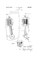
Other features, such as the bracing of the Th cam haft F b l th ti bly assembly, the mounting of the fixed contact and the gears E and C and the extremity of points and the arrangement of the springs atthe cam shaft D are all encased in the casing tribute to the success of the device. B, through which lubricant is caused to travel 25 Reference will be had to the accompanying and accumulate in the wick S in the cam shaft drawings forming a part of this specifica- F which latter is hollow for a portion of its tion and wherein like characters of reference length to accommodate the wicking. designate corresponding parts throughout A cap T fits over the upper extremity of the the several views, in which: cam shaft F and the bracket t retains the cap 30 Fig. 1 is a side elevation of the device with in position and also secures the assembly at a fragmentary showing of a gas engine; its upper end to the engine frame. Another Fig. 2 is an end elevation; and bracket V maybe provided to retain the parts Fig; 3 is a transverse section on line 33 of in their respective positions and in the pres- Fi 1. cut disclosure this bracket V is bolted at one 35 g conventional gas engine is indicated by end to the timer casing. The opposite end reference character A having a cam shaft will be fixed to any available portion of the B to whichis fixed the bevel gear C which engine frame. meshes with the gear E on the lower extrem- The disclosure in the present application is .ity of the cam shaft F. A plurality of cams f obviously for a four cylinder motor, or a are fixed to the cam shaft F near the upper eX- motor with four points of ignition. The same tremity thereof and actuate the Contact inventive idea could be utilized in motors of levers more clearly hereinafter described. other capacity by increasing the number of The assembly forming the present timer cams. contacts and contact levers. Except for structure is carried by a supporting bracket the change in the number of these elements including a base pla e G formed with spaced the balance of the structure will be substan alined upper and lower bearings g and g tially identical with that disclosed. The two respectively, through which the cam shaft F most important features of the present strucextends. Integral brackets H extend out ture consists in the provision of means for a wardly from the bearings g. g and support quick testing of the ignition system, an adthe pivot pin it upon which the contact levers justment of the contact points whereby the full power of the motor may be developed, and the system of lubrication which includes the accumulation of the oil in a wick reservoir and a dispensing from this wick reservoir to the various bearing surfaces.
What I claim as new and desire to secure by Letters Patent of the United States is:
1. A timer for internal combustion engines, comprising a substantially rectangular plate member, supporting means for said plate, a pair of spaced alined bearings formed on said plate intermediate the side edges of the latter, a plurality of fixed contacts carried by the plate adjacent one. side edge thereof, a
pair of spaced alined brackets formed on said plate adjacent its opposite side edge and eX- tending outwardly at substantially right angles thereto, a plurality of contacts pivotally supported between said brackets, means for normally urging the last named contacts into engagement with the fixed contacts, a rotatable shaft received in said bearings, a plurality of spaced cams carried by said shaft arranged to intermittently separate said contacts, and'means for actuating said shaft.
2. A timer for internal combustion engines, comprising a vertically disposed substantially rectangular plate member, supporting means for said plate, a bearing member formed adjacent the upper and lower portions of the plate and intermediate the side edges of the latter, a plurality of spaced alined fixed contacts carried by the plate ad jacent one side edge thereof, a pair of spaced alined brackets formed on said plate adjacent the opposite side edge of the latter and eX- tending outwardly at substantially right angles thereto, a series of spaced insulated contacts pivotally supported between said brackets, spring means carried by and extending outwardly at substantially right angles to said plate for normally urging the last named contacts into engagement with the fixed contacts, a hollow shaft rotatably supported in said bearings, spaced cams on said shaft arranged to intermittently separate said contacts, means within said shaft for lubricating the moving parts, and means for actuating the shaft.
In testimony whereof I affix my signature.
ARTHUR J. WOODFORD.
Priority Applications (1)
| Application Number | Priority Date | Filing Date | Title |
|---|---|---|---|
| US324374A US1854360A (en) | 1928-12-07 | 1928-12-07 | Timer |
Applications Claiming Priority (1)
| Application Number | Priority Date | Filing Date | Title |
|---|---|---|---|
| US324374A US1854360A (en) | 1928-12-07 | 1928-12-07 | Timer |
Publications (1)
| Publication Number | Publication Date |
|---|---|
| US1854360A true US1854360A (en) | 1932-04-19 |
Family
ID=23263319
Family Applications (1)
| Application Number | Title | Priority Date | Filing Date |
|---|---|---|---|
| US324374A Expired - Lifetime US1854360A (en) | 1928-12-07 | 1928-12-07 | Timer |
Country Status (1)
| Country | Link |
|---|---|
| US (1) | US1854360A (en) |
-
1928
- 1928-12-07 US US324374A patent/US1854360A/en not_active Expired - Lifetime
Similar Documents
| Publication | Publication Date | Title |
|---|---|---|
| US1854360A (en) | Timer | |
| DE975104C (en) | Device for mass balancing of the 2nd order for a high-speed four-cylinder four-stroke internal combustion engine | |
| US1699658A (en) | Combination oil reservoir, rocker arm, and main-support overhead-stamped bearing shaft | |
| US2065790A (en) | Internal combustion engine | |
| US2019558A (en) | Multicylinder internal combustion engine | |
| US1293712A (en) | Hydrocarbon-motor. | |
| US1795865A (en) | Hydraulic slack adjuster | |
| US2019138A (en) | Internal combustion engine | |
| US1605722A (en) | Rocker arm for internal-combustion engines | |
| US1742513A (en) | Roller bearing | |
| US1578331A (en) | Thrashing-machine-cylinder wrench | |
| US1555528A (en) | Commutator | |
| US3575579A (en) | Improved cam follower roller structure for distributor contact breaker arm | |
| US1272334A (en) | Electric-spark timer for gasolene-engines. | |
| US977885A (en) | Internal-combustion engine. | |
| US1349089A (en) | Spring-damper for valve mechanism | |
| US1547261A (en) | Best available copv | |
| US1881067A (en) | Control mounting | |
| US1640725A (en) | Ignition timer | |
| US1404015A (en) | Internal-combustion engine | |
| US1321580A (en) | Valve structure for internal-combustion motors | |
| US1827006A (en) | Internal combustion engine | |
| US1297105A (en) | Transmission mechanism for automobiles. | |
| US1369072A (en) | Timer | |
| US1607831A (en) | Ignition timer |