US1854320A - Collapsible reel - Google Patents
Collapsible reel Download PDFInfo
- Publication number
- US1854320A US1854320A US545503A US54550331A US1854320A US 1854320 A US1854320 A US 1854320A US 545503 A US545503 A US 545503A US 54550331 A US54550331 A US 54550331A US 1854320 A US1854320 A US 1854320A
- Authority
- US
- United States
- Prior art keywords
- crutches
- slides
- slots
- stops
- disk
- Prior art date
- Legal status (The legal status is an assumption and is not a legal conclusion. Google has not performed a legal analysis and makes no representation as to the accuracy of the status listed.)
- Expired - Lifetime
Links
- 241001589086 Bellapiscis medius Species 0.000 description 1
- 239000002131 composite material Substances 0.000 description 1
- 238000010276 construction Methods 0.000 description 1
- 238000004519 manufacturing process Methods 0.000 description 1
- PSGAAPLEWMOORI-PEINSRQWSA-N medroxyprogesterone acetate Chemical compound C([C@@]12C)CC(=O)C=C1[C@@H](C)C[C@@H]1[C@@H]2CC[C@]2(C)[C@@](OC(C)=O)(C(C)=O)CC[C@H]21 PSGAAPLEWMOORI-PEINSRQWSA-N 0.000 description 1
- 239000002184 metal Substances 0.000 description 1
Images
Classifications
-
- B—PERFORMING OPERATIONS; TRANSPORTING
- B65—CONVEYING; PACKING; STORING; HANDLING THIN OR FILAMENTARY MATERIAL
- B65H—HANDLING THIN OR FILAMENTARY MATERIAL, e.g. SHEETS, WEBS, CABLES
- B65H49/00—Unwinding or paying-out filamentary material; Supporting, storing or transporting packages from which filamentary material is to be withdrawn or paid-out
- B65H49/18—Methods or apparatus in which packages rotate
- B65H49/20—Package-supporting devices
- B65H49/30—Swifts or skein holders
-
- B—PERFORMING OPERATIONS; TRANSPORTING
- B65—CONVEYING; PACKING; STORING; HANDLING THIN OR FILAMENTARY MATERIAL
- B65H—HANDLING THIN OR FILAMENTARY MATERIAL, e.g. SHEETS, WEBS, CABLES
- B65H2701/00—Handled material; Storage means
- B65H2701/30—Handled filamentary material
- B65H2701/31—Textiles threads or artificial strands of filaments
Definitions
- This invention aims to provide a novel means'whereby an operator can release the hold of a reel on a skein of twine or the like, to permit the skein to be removed from the reel, the device being of peculiar utility in connection with reels which are placed on the spindles of twisters, in the manufacture of twine and similar products.
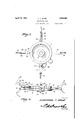
- Figure 1 shows in side elevation, a device constructed in accordance with the invention
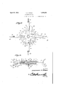
- Figure 2 is an elevation wherein the device is viewed edgewise, one slide being in section
- Figure 3 is an elevation showing the slides advanced, one member of the body being removed and parts being shown in section
- Figure 4 is a section on the line 44 of Figure 3
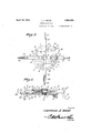
- Figure 5 is a view similar to Figure 3, but showing the slides retracted
- Figure 6 is a transverse section of the structure when the parts are arranged as shown in Figure 5.
- the device forming the subject matter of this application preferably is made of metal throughout. It comprises a body, which is a composite structure.
- the body is made up of two disk-like members 1 and 2 provided on their edges with inwardly extended flanges 3, as shown in the Figure 4.
- the member 1 of the body has pins 4 received in openings in the member 2 of the body.
- a securing device 6, preferably a tubular screw, shown in the Figure 6, can rotate in the member 2 of the body, but is threaded at 7 into the member 1 of the body, the, screw having a head 6 which overlaps the member 2 of the body, and holds the members 1 and 2 together.
- the members 1 and 2 of the body have pairs of parallel guide ribs 9 disposed 90 degrees apart, and in the flanges 3, there are openings 10, registering withthe spaces between the guide" ribs 9 of each pair.
- a disk 11 is mounted for limited rotation within the flange 3 of the body member 2, as shown in Figure 4, and this disk also turns on the screw 6, as Figure 3 will disclose.
- the disk 11 has curved slots 12.
- Outwardly extended slides 14 and 15 are mounted to reciprocate in the pairs of guide ribs 9, and in the openings 10, and the slides 14 and 15 have slots 16 in their innerends, in which the disk 11 is received.
- Shafts 17 are mounted in the inner ends of the slides 14 and 15 andextend across'the slots 16.
- Rollers 18 are journaled on the shafts 17, in the slots '16, and these rollers can move in the curved slots 12 of the disk 11. 7
- the slides 15 On their outer ends, the slides 15 have fixed crutches 19. .Movable crutches 20 are pivoted intermediate their ends, as shown at 21, to the outer ends of the slides 14. Intermediate their ends, the movable crutches '20 age provided with inwardly extendedarms Links 22 are disposed on the opposite sides of the movable crutches 20, and are connected thereto by pivot elements 23; -At their inner ends, the links 22 are connected by pins 24 which have limited movement in longitudinal slots 25 formed in stops 26 which project outwardly from the body member 1.
- the disk 11 has an outwardly extended arm 28 movablein' a slot 31 (Figure2) formed in the edge of the body member 1.
- the arm 28 carries the bracket 30, provided with a latch 29 adopted to engage one of the slides 15, externally of the body 1.
- the arms 27 on the movable crutches 20 lie against the stops 26, as shown in Figure 2, and the crutches cannot tip over in the direction of arrow B in Figure 2, and dump the twine.
- the crutches 20 cannot tip over in the direction of the arrow A in Figure 2 and dump the twine in that direction.
- the pins 24 in the links 22 are shown in Figure 2 as being spaced a little from the outer ends of the slots 25 in the stops 26, but the slight movement that the crutches 20 can have in the direction of the arrow A, due to the positioning of the pins 24; in the slots 25 does not amount to anything, so far as releasing the twine is concerned.
- a body slides mounted to reciprocate in the body, means under the control of an operator and carried by the body for moving the slides in and out, stops carried by the body, crutches pivoted to the slides and having arms engaging the stops to hold the crutches against tilting movement in one direction when the crutches are in working position, and links pivotal-1y connected to the crutches and slidable on the stops, the links cooperating with the stops to limit the tilting movement of the crutches in an opposite direction when the crutches are in working position.
Landscapes
- Rehabilitation Tools (AREA)
Description
Aprill9, 1932. A. WARD 1,854,320
COLLAPS IBLE REEL Filed June 19, 1951 S Sheets-Sheet l April 19, A W
COLLAPSIBLE REEL Filed June 19, 1931 3 Sheets-Sheet 2 W WM.
v9 Ri g; x03
amen Mm lazzweizce i. W7 6 A ril .19, 1932. L, A RD, 1,854,320
COLLA PS IBLE REEL Filed June 19 1951 3 Sheets-Sheet s I l lllilllllllllllll. L I" e v 20 N "2-K mm PatentedApr. 19, 1932.
'2. STTES UNIT QFFICE LAWRENCE A. WARD, OF SELMA, ALABAMA GOLLAPSIIBLE REEL Application filed June 19,
This invention aims to provide a novel means'whereby an operator can release the hold of a reel on a skein of twine or the like, to permit the skein to be removed from the reel, the device being of peculiar utility in connection with reels which are placed on the spindles of twisters, in the manufacture of twine and similar products.
It is within the province of the disclosure to improve generally and to enhance the utility of devices of that type to which the invention appertains.
With the above and other objects in view, which will appear as the description proceeds, the invention residesin the combination and arrangements of parts and in the details of construction hereinafter described and claimed, it being understood that changes in the precise embodiment of the invention herein disclosed, may be made within the scope of what is claimed, without departing from the spirit of the invention.
In the accompanying drawings Figure 1 shows in side elevation, a device constructed in accordance with the invention; Figure 2 is an elevation wherein the device is viewed edgewise, one slide being in section; Figure 3 is an elevation showing the slides advanced, one member of the body being removed and parts being shown in section; Figure 4 is a section on the line 44 of Figure 3; Figure 5 is a view similar to Figure 3, but showing the slides retracted; Figure 6 is a transverse section of the structure when the parts are arranged as shown in Figure 5. I
The device forming the subject matter of this application preferably is made of metal throughout. It comprises a body, which is a composite structure. The body is made up of two disk- like members 1 and 2 provided on their edges with inwardly extended flanges 3, as shown in the Figure 4. The member 1 of the body has pins 4 received in openings in the member 2 of the body.
1931. Serial No. 545,503.
A securing device 6, preferably a tubular screw, shown in the Figure 6, can rotate in the member 2 of the body, but is threaded at 7 into the member 1 of the body, the, screw having a head 6 which overlaps the member 2 of the body, and holds the members 1 and 2 together. V
I On their inner surfaces, the members 1 and 2 of the body have pairs of parallel guide ribs 9 disposed 90 degrees apart, and in the flanges 3, there are openings 10, registering withthe spaces between the guide" ribs 9 of each pair. p
A disk 11 is mounted for limited rotation within the flange 3 of the body member 2, as shown in Figure 4, and this disk also turns on the screw 6, as Figure 3 will disclose. The disk 11 has curved slots 12. I
Outwardly extended slides 14 and 15 are mounted to reciprocate in the pairs of guide ribs 9, and in the openings 10, and the slides 14 and 15 have slots 16 in their innerends, in which the disk 11 is received. Shafts 17 are mounted in the inner ends of the slides 14 and 15 andextend across'the slots 16. Rollers 18are journaled on the shafts 17, in the slots '16, and these rollers can move in the curved slots 12 of the disk 11. 7
On their outer ends, the slides 15 have fixed crutches 19. .Movable crutches 20 are pivoted intermediate their ends, as shown at 21, to the outer ends of the slides 14. Intermediate their ends, the movable crutches '20 age provided with inwardly extendedarms Links 22 are disposed on the opposite sides of the movable crutches 20, and are connected thereto by pivot elements 23; -At their inner ends, the links 22 are connected by pins 24 which have limited movement in longitudinal slots 25 formed in stops 26 which project outwardly from the body member 1.
The disk 11 has an outwardly extended arm 28 movablein' a slot 31 (Figure2) formed in the edge of the body member 1.
The arm 28 carries the bracket 30, provided with a latch 29 adopted to engage one of the slides 15, externally of the body 1.
Supposing that the latch 29 is engaged with one of the slides 15, and the slides are outwardly extended, as shown in Figure 3, the operator releases the latch 29 from the slide 15 and gives the disk 11 a slight turn, by means of the arm 28. Then the rollers 18 on the slides cooperate with the slots 12 in the disk 11 to draw the slides 14: and 15 inwa-rdly from the position of Figure 3 to the position of Figure 5.
When the slides 14 and 15 are outwardly extended, the arms 27 on the movable crutches 20 lie against the stops 26, as shown in Figure 2, and the crutches cannot tip over in the direction of arrow B in Figure 2, and dump the twine. Owing to the presence of the links 22, the crutches 20 cannot tip over in the direction of the arrow A in Figure 2 and dump the twine in that direction. In order to avoid fine machine work, the pins 24 in the links 22 are shown in Figure 2 as being spaced a little from the outer ends of the slots 25 in the stops 26, but the slight movement that the crutches 20 can have in the direction of the arrow A, due to the positioning of the pins 24; in the slots 25 does not amount to anything, so far as releasing the twine is concerned.
When the slides 14 move inwardly from the position of Figure 2, the crutches 20 first move inwardly, the pivot pins 24 moving inwardly in the slots 25. This inward movement of the crutches 20 brings the crutches against the outer ends of the stops 26, and as the inward movement of the slides 14 continues, the crutches 20 tilt, on the outer ends of the stops 26, as fulcrums, and the yarn or twine is discharged from the reel. As the crutches 20 tilt in the direction of the arrow A in Figure 2, the pivot point 23, moves in an arc, the center of which is the pivot element 21, and during this movement, the pivot pins 24 in the inner ends of the links 22 can move outwardly in the slots 25 of the stops 26. A reverse movement of the disk 11, by means of the arm 28, will restore the parts to the positions of Figures 3, 4: and 2.
Having thus described the invention what is claimed is:
1. In a reel of the class described, a body, slides mounted to reciprocate in the body, means under the control of an operator and carried by the body for moving the slides in and out, stops carried by the body, crutches pivoted to the slides and having arms engaging the stops to hold the crutches against tilting movement in one direction when the crutches are in working position, and links pivotal-1y connected to the crutches and slidable on the stops, the links cooperating with the stops to limit the tilting movement of the crutches in an opposite direction when the crutches are in working position. the slidable LAWRENCE A. WARD.
Priority Applications (1)
| Application Number | Priority Date | Filing Date | Title |
|---|---|---|---|
| US545503A US1854320A (en) | 1931-06-19 | 1931-06-19 | Collapsible reel |
Applications Claiming Priority (1)
| Application Number | Priority Date | Filing Date | Title |
|---|---|---|---|
| US545503A US1854320A (en) | 1931-06-19 | 1931-06-19 | Collapsible reel |
Publications (1)
| Publication Number | Publication Date |
|---|---|
| US1854320A true US1854320A (en) | 1932-04-19 |
Family
ID=24176512
Family Applications (1)
| Application Number | Title | Priority Date | Filing Date |
|---|---|---|---|
| US545503A Expired - Lifetime US1854320A (en) | 1931-06-19 | 1931-06-19 | Collapsible reel |
Country Status (1)
| Country | Link |
|---|---|
| US (1) | US1854320A (en) |
-
1931
- 1931-06-19 US US545503A patent/US1854320A/en not_active Expired - Lifetime
Similar Documents
| Publication | Publication Date | Title |
|---|---|---|
| GB898751A (en) | Method and machine for forming on a collapsible drum annular bands from one or more endless threads, more particularly for resisting structures of tyres for motor vehicle wheels | |
| US1854320A (en) | Collapsible reel | |
| US1000261A (en) | Collapsible mandrel. | |
| US1955917A (en) | Web roll support | |
| US2854233A (en) | Paper folding machine | |
| CN210029394U (en) | Prevent cloth type reel for spinning machine that drops | |
| US3628745A (en) | Winding shaft for roll-cutting machines | |
| US1803370A (en) | Fold-plate shifter | |
| CN211842824U (en) | Cutting mechanism of winder | |
| DE856515C (en) | Device for feeding the structural parts of a pneumatic vehicle tire to a drivable building drum | |
| CN210001350U (en) | drip irrigation tape recovery device | |
| CN218793682U (en) | Fire hose storage device for fire truck | |
| US1871900A (en) | Paper folding machine | |
| CN209097904U (en) | A kind of hospital gauze piece folding device | |
| US2312729A (en) | Bagmaking machine | |
| KR200473127Y1 (en) | paper bag manufacturing machine | |
| US2348605A (en) | Tucker blade motion for rotary folding mechanisms | |
| US1795929A (en) | Stitcher for tire-building machines | |
| US1523725A (en) | Swift machine | |
| US2802262A (en) | Tube cutter | |
| US905720A (en) | Automatic web-guiding device. | |
| CN212503083U (en) | Fabric processing and winding device | |
| US1752426A (en) | Folding mechanism | |
| US1714946A (en) | Knotter | |
| AU2007202431A1 (en) | Tissue Paper Cutting Mechanism Having Upper Knife with Variable Spiral Curve Angle and Upper Knife Structure Therefor |