US1854313A - Adjustable port for centrifuges - Google Patents
Adjustable port for centrifuges Download PDFInfo
- Publication number
- US1854313A US1854313A US474201A US47420130A US1854313A US 1854313 A US1854313 A US 1854313A US 474201 A US474201 A US 474201A US 47420130 A US47420130 A US 47420130A US 1854313 A US1854313 A US 1854313A
- Authority
- US
- United States
- Prior art keywords
- bowl
- ports
- port
- adjustable
- center
- Prior art date
- Legal status (The legal status is an assumption and is not a legal conclusion. Google has not performed a legal analysis and makes no representation as to the accuracy of the status listed.)
- Expired - Lifetime
Links
- 230000008859 change Effects 0.000 description 18
- 208000028659 discharge Diseases 0.000 description 15
- 239000012530 fluid Substances 0.000 description 12
- XLYOFNOQVPJJNP-UHFFFAOYSA-N water Substances O XLYOFNOQVPJJNP-UHFFFAOYSA-N 0.000 description 9
- 239000007788 liquid Substances 0.000 description 6
- 239000007787 solid Substances 0.000 description 6
- 238000010276 construction Methods 0.000 description 3
- 230000005484 gravity Effects 0.000 description 3
- 230000006872 improvement Effects 0.000 description 3
- 238000000746 purification Methods 0.000 description 3
- 238000005352 clarification Methods 0.000 description 2
- 238000000926 separation method Methods 0.000 description 2
- 239000010409 thin film Substances 0.000 description 2
- 239000002699 waste material Substances 0.000 description 2
- 240000008791 Antiaris toxicaria Species 0.000 description 1
- 241001052209 Cylinder Species 0.000 description 1
- 230000009471 action Effects 0.000 description 1
- 238000004140 cleaning Methods 0.000 description 1
- 239000010408 film Substances 0.000 description 1
- 239000012535 impurity Substances 0.000 description 1
- 230000014759 maintenance of location Effects 0.000 description 1
- 239000000463 material Substances 0.000 description 1
- 230000007246 mechanism Effects 0.000 description 1
- 238000000034 method Methods 0.000 description 1
- 230000008569 process Effects 0.000 description 1
- 238000009987 spinning Methods 0.000 description 1
Images
Classifications
-
- B—PERFORMING OPERATIONS; TRANSPORTING
- B04—CENTRIFUGAL APPARATUS OR MACHINES FOR CARRYING-OUT PHYSICAL OR CHEMICAL PROCESSES
- B04B—CENTRIFUGES
- B04B11/00—Feeding, charging, or discharging bowls
- B04B11/02—Continuous feeding or discharging; Control arrangements therefor
-
- Y—GENERAL TAGGING OF NEW TECHNOLOGICAL DEVELOPMENTS; GENERAL TAGGING OF CROSS-SECTIONAL TECHNOLOGIES SPANNING OVER SEVERAL SECTIONS OF THE IPC; TECHNICAL SUBJECTS COVERED BY FORMER USPC CROSS-REFERENCE ART COLLECTIONS [XRACs] AND DIGESTS
- Y10—TECHNICAL SUBJECTS COVERED BY FORMER USPC
- Y10S—TECHNICAL SUBJECTS COVERED BY FORMER USPC CROSS-REFERENCE ART COLLECTIONS [XRACs] AND DIGESTS
- Y10S411/00—Expanded, threaded, driven, headed, tool-deformed, or locked-threaded fastener
- Y10S411/924—Coupled nut and bolt
- Y10S411/929—Thread lock
Definitions
- GUSTAV B PETSCHE AND ALFRED npmssunn, or oLEvEmANnoHIo, AssI itoias TO THE N TI N ME OMPANX, OE CLEVELAND, QHI LACQR DRATION F OHI v ADJUSTABLE PORT FOR CENTRIFUGES Application filed August 9, 1930,; .Serial No,,474,201-.
- thefluid may not only be controlled but the apparatus quickly converted from a separator into a clarifier or vice versa and therefore the primary object of the present nvention is-the provision of acombinedcentrifuge and clarifier, quickly convertible one into the other, without the necessity of providing interchangeable parts and which is c0mpar-a-. tively simple in construction, thepresent im-- provement being a continuation in part ofv our contemporaneously pending application No. 390,975, filed September 7th, 1929. and, therefore it is deemed only necessary to show the upper half of that apparatus having par.- ticularly to do with the adjustable, ports.
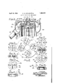
- Fig. 1 is a vertical, sectional view of the upper portion of; this improved centrifuge and separator.
- Fig. 2 i s.,a, top view of the bowl taken on thelline 272 of Fig. 1.
- Fig. is a, top view of one of the adjustab por 4c is. a: cross-sectional view thereof, taken ontheline of Fig. 3. Fig. 5, illustrates adifferent form of adjustable port.
- Fig, 6 is a. cross-secti0nal view thereof, taken on. the line 6 6 of Fig. 5.
- Fig. 7 isa top view,- of another form ofadjustable port.
- Fig. 8 is a cross-sectional view thereof, taken on theline 88 of Fig. 7 I
- Fig. 9 is a top view of another form of adiustableport.
- Fig. 10 is a. cross sectional view thereof, taken on the line 1010 of Fig. 9.
- a bowl-protecting shell or housing 27 Located around the bowl 23 is a bowl-protecting shell or housing 27 and this housing 27 is provided near its top with a waste-collecting chamber 28 having a discharge spout or pipe 29 and is closed by a cover 30 suitably secured to the housing 27 by clamps 31. Centrally of and carried by the cover is located a suitable inlet, including an inlet nozzle 32.
- the bowl 23 comprising the outer shell and a bottom is also provided with a top plate 33 suitably secured thereto, in which is mounted a series of rotatable plugs or plates 34 (see Fig. 2) each provided with outlet ports 35 opening into a chamber 36 between the top of the bowl and the cover 30 and which cham ber leads to the waste-collecting chamber 28.
- This bowl spindle head 37 has a cone-shaped chamber 39 at the top in communication with the inlet nozzle 32, and this head is provided in the bottom thereof with impelling ports 40 opening into the inner or first cylinder 43 of the bowl.
- This head is provided with a horizontally-located separating disk 41 and thereabove with ports 42 (which are designated herein as heavy fluid ports) and at the underside thereof with ports 42 (designated herein as light fluid ports).
- ports 42 are in communication with the ports 35 of the convertible plugs 34.
- the top of the bowl around the convertible plugs is provided with indicating marks whereby all of the plugs may be adjusted to the same extent, for which purpose the plugs are provided with slots 34.
- a pair of tubes or cylinders 43 and 44 Located within the bowl is a pair of tubes or cylinders 43 and 44 (the cylinder 43 being designated as the inner cylinder and the cylinder 44 as the outer cylinder), and the small inner cylinder or tube is supported at its top by the spindle head 37 and at its lower end by a centering ring, part of which is located between the inner cylinder 43 and the outer cylinder 44.
- This centering ring is supported on the bottom of the bowl and is provided with vertically-located ports (herein designated as light fluid ports) and with horizontally-located ports (herein des ignated as heavy fluid or impeller ports).
- This centering ring holds the tubes or cylinders 43 and 44 in position and separates tube 43 from tube 44.
- the lower end of the tube 44 is likewise carried by this ring, while the top thereof is supported by the spindle head 37 and at the top of this outer cylinder the ports 42 are located.
- the fluid enters through the nozzle 32 (see Fig. 1) into what is designated as the impeller cavity or cone chamber 39 and from thence passes through the exit ports 40 which are inclinedly-located and arranged at the extreme radius of this chamber so to give the fluid when leaving the chamber 39 approximately the same speed as the inner cylinder 43.
- the inner radius of this bowl cylinder 43 with reference to the distance of the exit ports in the bowl bottom from the axis of rotation, is such that only a film of fluid can remain on the surface of the cylin der 43 instead of being submergec by a heavy layer, so that this cylinder may properly be termed a dry one, as compared with the outer or larger cylinder 44 which is submerged.
- the bowl is easily dismantled and can be operated without the cylinders 43 and 4A and the bottom centering ring when purification of the material to be treated does not. have to be of high grade.
- the cylinders are not provided with any ports through their side walls at all and that the ports in communication with these cylinders or the chambers formed thereby are so located at the top and bottom of the bowl as to give highly efficient and superior results.
- the ports at the bottom are all carried by a centering ring readily inserted and removed and by the detachable bottom of the bowl, and at the top of the bowl by a spindle head and rotatable plugs, all of which likewise can be readily removed and replaced, thereby permitting quick and easy assemblage of the bowl parts andthe cleaning thereof; while the several chambers formed by the cylinders or tubes 43 and 44: are all properly spaced from each other by the same centering ring and spindle head, thus providing, in conjunction with a simple form of bowl, protecting housing having a waste chamber therein and cover therefor, a very simple and compact machine having the smallest number of parts and in which the bowl may be readily removed by slipping it from the spindle, and the bowl-protecting housing may also be removed, if desired, from the housing carrying the driving mechanism for the rotating spindle, since it may be secured thereto in any suitable way.
- adjustable plugs 34 having the outlet ports 35 eccentrically located relatively to the stationary outlet ports 42, thus doingentirely away with the necessity of providing interchangeable removable rings, and which plugs 3a are rotatable to change the radius of dis-. charge.
- the adjustment of these plugs does not change the diameter of the ports or orifices but only the location thereof relatively to the center of rotation, thereby to adjust the radius of discharge and at times to partially or completely close the discharge openings when the ports are out of communication with the ports 42, asfor instance, when the apparatus is converted into a clarifier, andat which time these ports 35 are over the solid part 41 of the separating disk 41 located adjacent to the discharge or duct 42.
- the plug is slotted transversely of its threads, as at 50, thus forming two elastic wings which are pinched together by means of a screw 51.
- a pair of such slots 50 are pro vided in each plug, thus forming a pair of elastic wings pinched together by a pair of screws 51'.
- the plug is made up of two parts 52 and 53, tied together by a pairs of screws 54, one of these parts or disks engaging a shoulder 55 of the bowl top, while the other part or disk has a flange or shoulder 56 for engaging the underside of the bowl top, whereby the two parts or disks may be clamped in engagement with the bowl top.
- the plug is shown as of conical form as at 57 and provided with threads 58 carrying a lock nut 59 for wedging the plug into its adjusted position, these various means forming a locking means for effectively locking the plug in position when adjusted in the manner hereinbefore described.
- threads 58 carrying a lock nut 59 for wedging the plug into its adjusted position
- a centrifuge In a centrifuge, the combination of a rotatable bowl, rotatable means located at the top of the bowl and provided with eccentrically-located outlet ports adjustable toward and from the center of rotation of the bowl to change the location thereof relatively to the center of rotation without changing the size of the ports, means adjacent to a discharge port and co-operating with said adjustable port for closing the latter when adjusted and locking means for locking said rotatable means in adjusted position and effective to exert a depthwise clamping action on said rotatable means.
- a centrifuge the combination of a ro tatable bowl, rotatable means located at the top of the bowl and provided with eccentrically-located outlet ports adjustable toward and from the center of rotation of the bowl to change the location thereof relatively to the center of rotation without changing the size of the ports, means adjacent to a discharge port and co-operating with said adjustable port for closing the latter when adjusted to change the centrifuge from a separator into a clarifier and locking means for locking said rotatable means in adjusted position, said locking means comprising clamping means.
- a centrifuge In a centrifuge, the combination of arotatable bowl, rotatable means located at the top of the bowl and provided with eccen trically-located outlet ports adjustable toward and from the center of rotation of the bowl to change the location thereof relatively to the center of rotation without changing the size of the ports, and locking means for locking said rotatable means in adjusted position, said locking means comprising clamping means, said clamping means comprising a plurality of spaced parts carried by the rotatable means and a clamping medium 00- operating with said spaced parts.
- a centrifuge the combination of a rotatable bowl, rotatable means located at the top of the bowl and provided with eccen trically-located outlet ports adjustable toward and from the center of rotation of the bowl to change the location thereof relatively to the center of rotation without changing the size of the ports, and locking means for locking said rotatable means in adjusted position, said locking means comprising a conical surface carried by the rotatable means and means for wedging said surface in the bowl top.
- a centrifuge the combination of a rotatable spindle, means for rotating it, a bowl carried thereby and having a closed top, and a plug located in the top and substantially flush with the top and bottom of the top and having a straight port therethrough from top to bottom thereof and adjustable toward and from the center of the bowl to change the location of the port relative to the center of rotation and means adjacent to a discharge port and co-operating with said adjustable port for closing the latter when adjusted for readily converting the separator into a clarifier without the removal of any parts.
- a centrifuge the combination of a rotatable spindle, means for rotating it, a bowl carried thereby and having a closed top, and a plug located in the top and having an eccentrically located straight port there through from top to bottom thereof and adjustable toward and from the center of the bowl to change the location of the port relative to the center of rotation and means adjacent to a discharge port and co-operating with said adjustable port for closing the latter when adjusted for readily converting the separator into a clarifier without the removal of any parts.
- a centrifuge In a centrifuge, the combination of a rotatable spindle, means for rotating it, a bowl carried thereby, an adjustable ported plug carried by the bowl and adjustable toward and from the center of the bowl to change the location of the port relative to the center of rotation and means adjacent to a discharge port and co-operating with said adjustable port for closing the latter when adjusted for converting the centrifuge from a separator into a clarifier, said plug having a radial slot spacing the parts thereof, and clamping means for pinching the spaced parts together, thereby to lock the plug in position.
- a centrifuge In a centrifuge, the combination of a rotatable spindle, means for rotating it, a bowl carried thereby, an adjustable ported plug carried by the bowl and adjustable toward and from the center of the bowl to change the location of the port relative to the center of rotation and means adjacent to a discharge port and co-operating with said adjustable port for closing the latter when adjusted for converting the centrifuge from a separator into a clarifier, said plug comprising a pair of spaced members and means projecting therethrough for drawing the members toward each other, thereby to lock the plug in position.
Landscapes
- Centrifugal Separators (AREA)
Description
I April 19, 1932. (5.. B. PETcHE ET AL 1,854,313
ADJUSTABLE PORT FOR CENTRIFUGES Filed Aug. 9, 1930 INVENTO'RS; Guam/5.2 6556% figfr ecllilpfissmew RNEY Patented Apr. 19, 1932 UNE'IEEE PATENT series;
GUSTAV B. PETSCHE AND ALFRED npmssunn, or oLEvEmANnoHIo, AssI itoias TO THE N TI N ME OMPANX, OE CLEVELAND, QHI LACQR DRATION F OHI v ADJUSTABLE PORT FOR CENTRIFUGES Application filed August 9, 1930,; .Serial No,,474,201-.
adjustable ports, whereby the condition of.
- thefluidmay not only be controlled but the apparatus quickly converted from a separator into a clarifier or vice versa and therefore the primary object of the present nvention is-the provision of acombinedcentrifuge and clarifier, quickly convertible one into the other, without the necessity of providing interchangeable parts and which is c0mpar-a-. tively simple in construction, thepresent im-- provement being a continuation in part ofv our contemporaneously pending application No. 390,975, filed September 7th, 1929. and, therefore it is deemed only necessary to show the upper half of that apparatus having par.- ticularly to do with the adjustable, ports.
In the purifying of liquids by centrifuge force, the best efiiciency is obtainediby having the liquid travel through the revolving bowlin thin layers or strata and. also; have it remaln 1n the bowl aslong as poss ble, since impurities require time to. settle out of the liquid and this time is reduced by reducing the thickness of the layers. This is alSOtrue of theseparation of two liquids of different specific gravities. When purifying liquids from which solids only have to-be removed, the centrifuge is set upas a clarifier and in that case the solids accumulate within the bowl and have to be removed from time to time, with the consequent interruption in the operation of the machineunlessa carrier liq-. uid is used to carry away the solidsthrough special discharge ports to prevent accumulalIIOn;
In separators the locationor distance; of the discharge ports with reference to theaxis of rotation is very important. These discharge ports correspond to and have to vary with the variation of the specific gravities; otherwise, if water,.for instance, isto be separated from oil and the distance of the overflow for the oil is too-close toward the axis of rotation, an undue amount of oil will dis charge, with the water, and if too far away then part of the waterdischarges with the oil. It has heretofore been the usual practice to have one port stationary and theother adjustable by interchangeable rings ofdifferent size or; bore. To interchange these rings. is a. time-taking and rather troublesomemanipulation as sometimes several have toibetriedout before the right one is found, and, ofcourse, a great number of ringshave tobe on hand. soas to be prepared for separating liquids of various kinds.
'lherefore, thepresent improvement is intendedto eliminatethesedifficulties and provide anapparatus. useful either as av centrifuge or as a clarifier-and.convertible from one tothe other without the necessity of using interchangeable parts and making certain adjustments. Other important advantages of thisimprovementgwill appear in the detailed description thereof.
In the drawings accompanying and. form.- ing a partof this specification:
Fig. 1 is a vertical, sectional view of the upper portion of; this improved centrifuge and separator.
Fig. 2 i s.,a, top view of the bowl taken on thelline 272 of Fig. 1.
Fig. is a, top view of one of the adjustab por 4c is. a: cross-sectional view thereof, taken ontheline of Fig. 3. Fig. 5, illustrates adifferent form of adjustable port.
7 Fig, 6 is a. cross-secti0nal view thereof, taken on. the line 6 6 of Fig. 5.
Fig. 7 isa top view,- of another form ofadjustable port.
Fig. 8 is a cross-sectional view thereof, taken on theline 88 of Fig. 7 I
Fig. 9 is a top view of another form of adiustableport;
Fig. 10 is a. cross sectional view thereof, taken on the line 1010 of Fig. 9.
Similar characters of reference indicate corresponding parts in theseveral views.
Before explaining inv detail the; present improvement and mode of operation, thereof, we desire to have it understood that the invention is not limited to the details of construction and arrangement of parts which are illustrated in the accompanying drawings, since the invention is capable of other embodiments, and that the phraseology which we employ is for the purpose of description and not of limitation.
Located around the bowl 23 is a bowl-protecting shell or housing 27 and this housing 27 is provided near its top with a waste-collecting chamber 28 having a discharge spout or pipe 29 and is closed by a cover 30 suitably secured to the housing 27 by clamps 31. Centrally of and carried by the cover is located a suitable inlet, including an inlet nozzle 32. The bowl 23 comprising the outer shell and a bottom is also provided with a top plate 33 suitably secured thereto, in which is mounted a series of rotatable plugs or plates 34 (see Fig. 2) each provided with outlet ports 35 opening into a chamber 36 between the top of the bowl and the cover 30 and which cham ber leads to the waste-collecting chamber 28.
By rotating the plugs 34 to carry the outlet ports 35 toward the center of the bowl, the center of these holes will be much nearer to the center of the bowl, consequently, when the bowl is spinning, normally no fluid will discharge through the ports 35. only through the ports provided at the bottom of the bowl, thus the separator is converted into a clarifier in which the solids which accumulate inside of the bowl must be removed at intervals by the operator. Carried by the upper end of the rotating spindle 4, which is reduced for the purpose, is a bowl spindle head 37 which is also supported by a supporting tube 38. This bowl spindle head 37 has a cone-shaped chamber 39 at the top in communication with the inlet nozzle 32, and this head is provided in the bottom thereof with impelling ports 40 opening into the inner or first cylinder 43 of the bowl. This head is provided with a horizontally-located separating disk 41 and thereabove with ports 42 (which are designated herein as heavy fluid ports) and at the underside thereof with ports 42 (designated herein as light fluid ports). The
ports 42 are in communication with the ports 35 of the convertible plugs 34. The top of the bowl around the convertible plugs is provided with indicating marks whereby all of the plugs may be adjusted to the same extent, for which purpose the plugs are provided with slots 34.
Located within the bowl is a pair of tubes or cylinders 43 and 44 (the cylinder 43 being designated as the inner cylinder and the cylinder 44 as the outer cylinder), and the small inner cylinder or tube is supported at its top by the spindle head 37 and at its lower end by a centering ring, part of which is located between the inner cylinder 43 and the outer cylinder 44. This centering ring is supported on the bottom of the bowl and is provided with vertically-located ports (herein designated as light fluid ports) and with horizontally-located ports (herein des ignated as heavy fluid or impeller ports).
This centering ring holds the tubes or cylinders 43 and 44 in position and separates tube 43 from tube 44. The lower end of the tube 44 is likewise carried by this ring, while the top thereof is supported by the spindle head 37 and at the top of this outer cylinder the ports 42 are located.
In operation, the fluid enters through the nozzle 32 (see Fig. 1) into what is designated as the impeller cavity or cone chamber 39 and from thence passes through the exit ports 40 which are inclinedly-located and arranged at the extreme radius of this chamber so to give the fluid when leaving the chamber 39 approximately the same speed as the inner cylinder 43. The inner radius of this bowl cylinder 43, with reference to the distance of the exit ports in the bowl bottom from the axis of rotation, is such that only a film of fluid can remain on the surface of the cylin der 43 instead of being submergec by a heavy layer, so that this cylinder may properly be termed a dry one, as compared with the outer or larger cylinder 44 which is submerged.
This construction facilitates the separation and clarification to a great extent, as it a well-known fact that with a thin film .under centrifugal force, water, oil and dirt separate almost instantly. The water within the oil may be distributed in atom size, but in a thin film under pressure forms drops. This takes place before the fluid under pressure leaves the inner cylinder 43. In this state the fluid enters through the horizontal impeller ports at the bottom of the bowl and passes into what may be termed the accumulating chamber 44 formed between the outer cylinder 44 and the bowl shell 23. Here the water, oil and residue form strata, the oil nearest to the axis of rotation, the residue at the extreme radius, and the water between the two. Owing to the greatest centrifugal force in this part of the bowl. the most extensive separation and clarification take place, assisted by the long travel over the whole length of the bowl and the parallel flow from the bottom to the top. After this the water and residue discharge from the chamber 44 around the separating disk 41 which extends nearly across the top thereof to the bowl shell 23 and through the horizontal ports 42 and ports 35 into the chamber or trough 28 and thence through the waste pipe 29; while the oil passes through ports 42. into the intermediate chamber 43 formed between the inner cylinder 43 and the outer cylinder 44, where the oil receives an additional purification before it leaves through the vertical ports at the bottom of the bowl and thence is passed into an oil chamber and from thence through a clean discharge opening or pipe. Thus the oil has to travel three times the length of the bowl, continually eX- posed to centrifugal force, While going through the process of purification. Should it be found that it still contains some water or some oil discharges with the Water, then a slight adjustment of the convertible plugs 34, thereby to change the radius of discharge, will correct this. As hereinbefore stated, when it is desired to remove the solids from a fluid without separating one from the other, these convertible plugs 34 are rotated into the position nearest the center of the bowl, thus closing them, whereby the separator is converted into a clarifier in which the solids accumulate until they are removed at intervals by the operator.
The bowl is easily dismantled and can be operated without the cylinders 43 and 4A and the bottom centering ring when purification of the material to be treated does not. have to be of high grade.
From the foregoing it will be observed that the cylinders are not provided with any ports through their side walls at all and that the ports in communication with these cylinders or the chambers formed thereby are so located at the top and bottom of the bowl as to give highly efficient and superior results. Furthermore, the ports at the bottom are all carried by a centering ring readily inserted and removed and by the detachable bottom of the bowl, and at the top of the bowl by a spindle head and rotatable plugs, all of which likewise can be readily removed and replaced, thereby permitting quick and easy assemblage of the bowl parts andthe cleaning thereof; while the several chambers formed by the cylinders or tubes 43 and 44: are all properly spaced from each other by the same centering ring and spindle head, thus providing, in conjunction with a simple form of bowl, protecting housing having a waste chamber therein and cover therefor, a very simple and compact machine having the smallest number of parts and in which the bowl may be readily removed by slipping it from the spindle, and the bowl-protecting housing may also be removed, if desired, from the housing carrying the driving mechanism for the rotating spindle, since it may be secured thereto in any suitable way.
One of the important features of the present improvement is-the provision of the adjustable plugs 34: having the outlet ports 35 eccentrically located relatively to the stationary outlet ports 42, thus doingentirely away with the necessity of providing interchangeable removable rings, and which plugs 3a are rotatable to change the radius of dis-. charge. The adjustment of these plugs does not change the diameter of the ports or orifices but only the location thereof relatively to the center of rotation, thereby to adjust the radius of discharge and at times to partially or completely close the discharge openings when the ports are out of communication with the ports 42, asfor instance, when the apparatus is converted into a clarifier, andat which time these ports 35 are over the solid part 41 of the separating disk 41 located adjacent to the discharge or duct 42.
By rotating the ports toward or from the center of rotation of the bowl, they may be adjusted to suit the specific gravity of the fluids to be separated. It has been found however, in practice, that it is not desirable to depend upon the frictional engagement of the adjustable plugs in the walls of their openings to hold these plugs in position after they have been carefully set and the machine has been in operation some time and therefore it is important to have locking means to prevent the shifting of the'plugs after they have been set.
In one form of locking means, the plug is slotted transversely of its threads, as at 50, thus forming two elastic wings which are pinched together by means of a screw 51. In Figs. 7 and 8 a pair of such slots 50 are pro vided in each plug, thus forming a pair of elastic wings pinched together by a pair of screws 51'. In Figs. 5 and 6, the plug is made up of two parts 52 and 53, tied together by a pairs of screws 54, one of these parts or disks engaging a shoulder 55 of the bowl top, while the other part or disk has a flange or shoulder 56 for engaging the underside of the bowl top, whereby the two parts or disks may be clamped in engagement with the bowl top. In Figs. 9 and 10, the plug is shown as of conical form as at 57 and provided with threads 58 carrying a lock nut 59 for wedging the plug into its adjusted position, these various means forming a locking means for effectively locking the plug in position when adjusted in the manner hereinbefore described. In other words,it has been found in practice that a plug merely screwed into the top of the cover does not retain its adjustment during the operation of the apparatus,
structing and using the same, although with- 7 out attempting to set forth all of the forms in which it may be made or all of the modes of its use, we claim:
1.-In a centrifuge, the combination of a' rotatable spindle, means for rotating-it, a bowl carried thereby, adjustable ported means carried by the bowl and adjustable toward and from the center of the bowl to change the location of the port relatively to the center of rotation for converting the ice 7 therefore, we have provided efficient means to insure the retention of the plugs in their centrifuge from a separatorinto a clarifier, and locking means effective depthwise of the ported means for locking said ported means in adjusted position and means adjacent to a. discharge port and co-operating with said adjustable port for closing the latter when rotatably adjusted.
2, In a centrifuge, the combination of a rotatable bowl, rotatable means located at the top of the bowl and provided with eccentrically-located outlet ports adjustable toward and from the center of rotation of the bowl to change the location thereof relatively to the center of rotation without changing the size of the ports, means adjacent to a discharge port and co-operating with said adjustable port for closing the latter when adjusted and locking means for locking said rotatable means in adjusted position and effective to exert a depthwise clamping action on said rotatable means.
3. In a. centrifuge, the combination of a ro tatable bowl, rotatable means located at the top of the bowl and provided with eccentrically-located outlet ports adjustable toward and from the center of rotation of the bowl to change the location thereof relatively to the center of rotation without changing the size of the ports, means adjacent to a discharge port and co-operating with said adjustable port for closing the latter when adjusted to change the centrifuge from a separator into a clarifier and locking means for locking said rotatable means in adjusted position, said locking means comprising clamping means.
4;. In a centrifuge, the combination of arotatable bowl, rotatable means located at the top of the bowl and provided with eccen trically-located outlet ports adjustable toward and from the center of rotation of the bowl to change the location thereof relatively to the center of rotation without changing the size of the ports, and locking means for locking said rotatable means in adjusted position, said locking means comprising clamping means, said clamping means comprising a plurality of spaced parts carried by the rotatable means and a clamping medium 00- operating with said spaced parts.
5. In a centrifuge, the combination of a rotatable bowl, rotatable means located at the top of the bowl and provided with eccen trically-located outlet ports adjustable toward and from the center of rotation of the bowl to change the location thereof relatively to the center of rotation without changing the size of the ports, and locking means for locking said rotatable means in adjusted position, said locking means comprising a conical surface carried by the rotatable means and means for wedging said surface in the bowl top.
6. In a centrifuge, the combination of a rotatable spindle, means for rotating it, a
bowl carried thereby and having a closed top, a plug located in the top and having a straight port therethrough from top to bottom thereof and adjustable toward and from the center of the bowl. to change the location of the port relative to the center of rotation and closable by its adjustment for readily converting the separator into a clarifier without the removal of any parts and means adjacent to a discharge duct and co-operating with said port whereby when the port is adjusted it will be closed.
7. In a centrifuge, the combination of a rotatable spindle, means for rotating it, a bowl carried thereby and having a closed top, and a plug located in the top and substantially flush with the top and bottom of the top and having a straight port therethrough from top to bottom thereof and adjustable toward and from the center of the bowl to change the location of the port relative to the center of rotation and means adjacent to a discharge port and co-operating with said adjustable port for closing the latter when adjusted for readily converting the separator into a clarifier without the removal of any parts.
8. In a centrifuge, the combination of a rotatable spindle, means for rotating it, a
bowl carried thereby and having a closed top,
a plurality of plugs located in the top and having a straight port therethrough from top to bottom thereof and adjustable toward and from the center of the bowl to change the location of the port relative to the center of rotation and means adjacent to a discharge port and co-operating with said adjustable port for closing the latter when adjusted for readily converting the separator into a clarifier without the removal of any parts.
9. In a centrifuge, the combination of a rotatable spindle, means for rotating it, a bowl carried thereby and having a closed top, a plurality of plugs located in the top and having a straight port therethrough from top to bottom thereof and adjustable toward and from the center of the bowl to change the location of the port relative to the center of rotation and means adjacent to a discharge port and co-operating with said adjustable port for closing the latter when adjusted for readily converting the separator into a clarifier without the removal of any parts, and means for insuring the same adjustable movement of each of said plugs.
10. In a centrifuge, the combination of a rotatable spindle, means for rotating it, a bowl carried thereby and having a closed top, and a plug located in the top and having an eccentrically located straight port there through from top to bottom thereof and adjustable toward and from the center of the bowl to change the location of the port relative to the center of rotation and means adjacent to a discharge port and co-operating with said adjustable port for closing the latter when adjusted for readily converting the separator into a clarifier without the removal of any parts.
11. In a centrifuge, the combination of a rotatable spindle, means for rotating it, a bowl carried thereby and having a top there for, a plurality of plugs located in the top, each having an eccentrically located straight port therethrough fro-m top to bottom thereof and adjustable toward and from the center of the bowl tochange the location of the port relative to the center of rotation and means adjacent to a discharge port and C o-operating with said adjustable port for closing the latter when adjusted for readily converting the separator into a clarifier without the removal of any parts.
12. In a centrifuge, the combination of a rotatable spindle, means for rotating it, a bowl carried thereby and having a closed to a plug located in the top and havingastraig t port therethrough from top to bottom there of and adjustable toward and from the center of the bowl to change the location of the port relative to the center of rotation and means adjacent to a discharge port and cooperating with said adjustable port for closing the latter when adjusted for readily converting the separator into a clarifier without the removal of any parts, and means for locking said ported plug in adjusted position.
13. In a centrifuge, the combination of a rotatable spindle, means for rotating it, a bowl carried thereby, an adjustable ported plug carried by the bowl and adjustable toward and from the center of the bowl to change the location of the port relative to the center of rotation and means adjacent to a discharge port and co-operating with said adjustable port for closing the latter when adjusted for converting the centrifuge from a separator into a clarifier, said plug having a radial slot spacing the parts thereof, and clamping means for pinching the spaced parts together, thereby to lock the plug in position.
is. In a centrifuge, the combination of a rotatable spindle, means for rotating it, a bowl carried thereby, an adjustable ported plug carried by the bowl and adjustable toward and from the center of the bowl to change the location of the port relative to the center of rotation and means adjacent to a discharge port and co-operating with said adjustable port for closing the latter when adjusted for converting the centrifuge from a separator into a clarifier, said plug comprising a pair of spaced members and means projecting therethrough for drawing the members toward each other, thereby to lock the plug in position.
15. In a centrifuge, the combination of a rotatable bowl, a plurality of rotatable plugs 1 located at the top of the bowl and provided with eccentrically located outlet ports adjustable toward and from the center of rotation of the bowl to change the location thereof relative to the center of rotation, means adjacent to discharge ports and co-operating with said adjustable discharge ports for closing the latter when adjusted thereby to convert the centrifuge from a separator into a clarifier each of said plugs comprising a pair of spaced portions, means for drawing said portions together thereby to lock the plug, and means for insuring the same adjustable movement of each of said plugs.
Signed at Cleveland, Ohio, this 5 day of August, 1930.
- GUSTAV B. PETSCHE.
ALFRED E. DRISSNER.
Priority Applications (1)
| Application Number | Priority Date | Filing Date | Title |
|---|---|---|---|
| US474201A US1854313A (en) | 1930-08-09 | 1930-08-09 | Adjustable port for centrifuges |
Applications Claiming Priority (1)
| Application Number | Priority Date | Filing Date | Title |
|---|---|---|---|
| US474201A US1854313A (en) | 1930-08-09 | 1930-08-09 | Adjustable port for centrifuges |
Publications (1)
| Publication Number | Publication Date |
|---|---|
| US1854313A true US1854313A (en) | 1932-04-19 |
Family
ID=23882583
Family Applications (1)
| Application Number | Title | Priority Date | Filing Date |
|---|---|---|---|
| US474201A Expired - Lifetime US1854313A (en) | 1930-08-09 | 1930-08-09 | Adjustable port for centrifuges |
Country Status (1)
| Country | Link |
|---|---|
| US (1) | US1854313A (en) |
Cited By (6)
| Publication number | Priority date | Publication date | Assignee | Title |
|---|---|---|---|---|
| US4950219A (en) * | 1988-10-20 | 1990-08-21 | Alfa-Laval Ab | Adjustable weir structure for a decanter centrifuge |
| US5944648A (en) * | 1996-10-15 | 1999-08-31 | Cornay; Paul J. | Concentric tubular centrifuge |
| US20040142807A1 (en) * | 1997-10-14 | 2004-07-22 | Cornay Paul J. | Concentric tubular centrifuge |
| US6808481B1 (en) | 1996-10-15 | 2004-10-26 | Erth Technologies, Inc. | Concentric tubular centrifuge |
| US20050054507A1 (en) * | 1996-10-15 | 2005-03-10 | Cornay Paul J. | Concentric tubular centrifuge |
| US20060258522A1 (en) * | 2003-08-30 | 2006-11-16 | Cornay Paul J | Centrifuge |
-
1930
- 1930-08-09 US US474201A patent/US1854313A/en not_active Expired - Lifetime
Cited By (10)
| Publication number | Priority date | Publication date | Assignee | Title |
|---|---|---|---|---|
| US4950219A (en) * | 1988-10-20 | 1990-08-21 | Alfa-Laval Ab | Adjustable weir structure for a decanter centrifuge |
| US5944648A (en) * | 1996-10-15 | 1999-08-31 | Cornay; Paul J. | Concentric tubular centrifuge |
| US6142924A (en) * | 1996-10-15 | 2000-11-07 | Erth Llc | Concentric tubular centrifuge |
| US6808481B1 (en) | 1996-10-15 | 2004-10-26 | Erth Technologies, Inc. | Concentric tubular centrifuge |
| US20050054507A1 (en) * | 1996-10-15 | 2005-03-10 | Cornay Paul J. | Concentric tubular centrifuge |
| US20040142807A1 (en) * | 1997-10-14 | 2004-07-22 | Cornay Paul J. | Concentric tubular centrifuge |
| US6966874B2 (en) | 1997-10-14 | 2005-11-22 | Erth Technologies, Inc. | Concentric tubular centrifuge |
| US7189196B2 (en) | 1997-10-14 | 2007-03-13 | Erth Technologies, Inc. | Method of separating materials with a concentric tubular centrifuge |
| US20060258522A1 (en) * | 2003-08-30 | 2006-11-16 | Cornay Paul J | Centrifuge |
| US7241256B2 (en) | 2003-08-30 | 2007-07-10 | Erth Technologies, Inc. | Centrifuge |
Similar Documents
| Publication | Publication Date | Title |
|---|---|---|
| SU1088652A3 (en) | Centrifugal separator | |
| GB726596A (en) | Improvements in or relating to centrifuges for separating, sludge containing liquids | |
| US2344888A (en) | Centrifugal separator | |
| ES402125A1 (en) | Centrifugal separator | |
| GB287056A (en) | Improvements relating to centrifugal machines and the centrifugal separation of liquids from mixtures of liquids and solid particles | |
| US1854313A (en) | Adjustable port for centrifuges | |
| US2173579A (en) | Centrifugal cream separator | |
| US2178547A (en) | Centrifugal separator | |
| DK159908B (en) | Centrifuge with energy recovery | |
| US1783546A (en) | Centrifuge | |
| US3145173A (en) | Centrifuge having forced solids discharge | |
| GB260071A (en) | Improvements in and relating to centrifugal separators | |
| US1917422A (en) | Arrangement in connection with centrifugal bowls | |
| US2169300A (en) | Regulable and power consuming reducing discharge device for centrifugal separators | |
| US2641363A (en) | Apparatus for clarifying liquids | |
| US2302382A (en) | Removal of impurities from soap nigre | |
| US1356665A (en) | Centrifugal separator and process | |
| US1422852A (en) | Centrifugal machine | |
| RU2283698C2 (en) | Screw centrifuge | |
| GB371755A (en) | Improvements in centrifugal separators | |
| US1935117A (en) | Centrifugal separating bowl | |
| US1016366A (en) | Liquid-separator. | |
| SU8000A1 (en) | Continuous centrifuge for liquid mixture separation | |
| US1688838A (en) | Drum for centrifugal separating apparatus | |
| US1749538A (en) | Clarifier bowl |